Voice-over-Internet Protocol
Release
6.3.0, Rev. 02
Published: 2012-12-10 Revision 02
Juniper Networks, Junos, Steel-Belted Radius, NetScreen, and ScreenOS are registered trademarks of Juniper Networks, Inc. in the United States and other countries. JunosE is a trademark of Juniper Networks, Inc. All other trademarks, service marks, registered trademarks, or registered service marks are the property of their respective owners.
Juniper Networks assumes no responsibility for any inaccuracies in this document. Juniper Networks reserves the right to change, modify, transfer, or otherwise revise this publication without notice.
Products made or sold by Juniper Networks or components thereof might be covered by one or more of the following patents that are owned by or licensed to Juniper Networks: U.S. Patent Nos. 5,473,599, 5,905,725, 5,909,440, 6,192,051, 6,333,650, 6,359,479, 6,406,312, 6,429,706, 6,459,579, 6,493,347, 6,538,518, 6,538,899, 6,552,918, 6,567,902, 6,578,186, and 6,590,785.
Copyright © 2009, Juniper Networks, Inc. All rights reserved.
Revision History
December 2012—Revision 02
Content subject to change. The information in this document is current as of the date listed in the revision history.
SOFTWARE LICENSE
The terms and conditions for using this software are described in the software license contained in the acknowledgment to your purchase order or, to the extent applicable, to any reseller agreement or end-user purchase agreement executed between you and Juniper Networks. By using this software, you indicate that you understand and agree to be bound by those terms and conditions.
Generally speaking, the software license restricts the manner in which you are permitted to use the software and may contain prohibitions against certain uses. The software license may state conditions under which the license is automatically terminated. You should consult the license for further details.
For complete product documentation, please see the Juniper Networks Website atwww.juniper.net/techpubs. END USER LICENSE AGREEMENT
The Juniper Networks product that is the subject of this technical documentation consists of (or is intended for use with) Juniper Networks software. Use of such software is subject to the terms and conditions of the End User License Agreement (“EULA”) posted at
http://www.juniper.net/support/eula.html. By downloading, installing or using such software, you agree to the terms and conditions of that EULA.
About This Guide . . . xiii
Part 1
VOIP
Chapter 1 H.323 Application Layer Gateway . . . 3Chapter 2 Session Initiation Protocol Application Layer Gateway . . . 15
Chapter 3 Media Gateway Control Protocol Application Layer Gateway . . . 65
Chapter 4 Skinny Client Control Protocol Application Layer Gateway . . . 79
Chapter 5 Apple iChat Application Layer Gateway . . . 107
Part 2
Index
Index . . . 123About This Guide . . . xiii
Document Conventions . . . xiii
Document Feedback . . . xvi
Requesting Technical Support . . . xvi
Part 1
VOIP
Chapter 1 H.323 Application Layer Gateway . . . 3Overview . . . 3
Alternate Gatekeeper . . . 3
Examples . . . 4
Example: Gatekeeper in the Trust Zone . . . 4
WebUI . . . 4
CLI . . . 5
Example: Gatekeeper in the Untrust Zone . . . 5
WebUI . . . 6
CLI . . . 6
Example: Outgoing Calls with NAT . . . 7
WebUI . . . 7
CLI . . . 9
Example: Incoming Calls with NAT . . . 9
WebUI . . . 10
CLI . . . 11
Example: Gatekeeper in the Untrust Zone with NAT . . . 12
WebUI . . . 12
CLI . . . 14
Chapter 2 Session Initiation Protocol Application Layer Gateway . . . 15
Overview . . . 15
SIP Request Methods . . . 16
Classes of SIP Responses . . . 17
SIP Application Layer Gateway . . . 18
Session Description Protocol Sessions . . . 20
Pinhole Creation . . . 21
Session Inactivity Timeout . . . 22
SIP Attack Protection . . . 23
Example: SIP Protect Deny . . . 23
Example: Signaling-Inactivity and Media-Inactivity Timeouts . . . 23
Example: SIP Connection Maximum . . . 24
SIP with Network Address Translation . . . 25
Outgoing Calls . . . 26
Incoming Calls . . . 26
Forwarded Calls . . . 26
Call Termination . . . 27
Call Re-INVITE Messages . . . 27
Call Session Timers . . . 27
Call Cancellation . . . 27
Forking . . . 27
SIP Messages . . . 28
SIP Headers . . . 28
SIP Body . . . 30
SIP NAT Scenario . . . 30
Examples . . . 32
Incoming SIP Call Support Using the SIP Registrar . . . 32
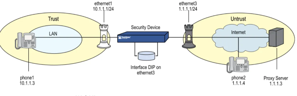
Example: Incoming Call (Interface DIP) . . . 34
Example: Incoming Call (DIP Pool) . . . 36
Example: Incoming Call with MIP . . . 38
Example: Proxy in the Private Zone . . . 40
Example: Proxy in the Public Zone . . . 42
Example: Three-Zone, Proxy in the DMZ . . . 44
Example: Untrust Intrazone . . . 48
Example: Trust Intrazone . . . 51
Example: Full-Mesh VPN for SIP . . . 53
Bandwidth Management for VoIP Services . . . 61
Chapter 3 Media Gateway Control Protocol Application Layer Gateway . . . 65
Overview . . . 65 MGCP Security . . . 66 About MGCP . . . 66 Entities in MGCP . . . 66 Endpoint . . . 66 Connection . . . 67 Call . . . 67 Call Agent . . . 67 Commands . . . 68 Response Codes . . . 70 Examples . . . 71
Media Gateway in Subscribers’ Homes—Call Agent at the ISP . . . 71
WebUI . . . 72
CLI . . . 73
ISP-Hosted Service . . . 74
WebUI . . . 74
CLI . . . 76
Chapter 4 Skinny Client Control Protocol Application Layer Gateway . . . 79
Overview . . . 79
About SCCP . . . 80 SCCP Components . . . 80 SCCP Client . . . 81 Call Manager . . . 81 Cluster . . . 81 SCCP Transactions . . . 81 Client Initialization . . . 82 Client Registration . . . 82 Call Setup . . . 83 Media Setup . . . 83
SCCP Control Messages and RTP Flow . . . 83
SCCP Messages . . . 84
Examples . . . 85
Example: Call Manager/TFTP Server in the Trust Zone . . . 86
WebUI . . . 86
CLI . . . 87
Example: Call Manager/TFTP Server in the Untrust Zone . . . 88
WebUI . . . 88
CLI . . . 89
Example: Three-Zone, Call Manager/TFTP Server in the DMZ . . . 90
WebUI . . . 90
CLI . . . 92
Example: Intrazone, Call Manager/TFTP Server in Trust Zone . . . 93
WebUI . . . 93
CLI . . . 95
Example: Intrazone, Call Manager/TFTP Server in Untrust Zone . . . 96
WebUI . . . 97
CLI . . . 98
Example: Full-Mesh VPN for SCCP . . . 98
WebUI (for Central) . . . 99
CLI (for Central) . . . 101
WebUI (for Branch Office 1) . . . 102
CLI (for Branch Office 1) . . . 103
WebUI (for Branch Office 2) . . . 104
CLI (for Branch Office 2) . . . 106
Chapter 5 Apple iChat Application Layer Gateway . . . 107
Overview . . . 107
Configuring the AppleiChat ALG . . . 108
WebUI . . . 108 CLI . . . 108 WebUI . . . 109 CLI . . . 109 WebUI . . . 109 CLI . . . 109
Configuration Examples . . . 109
Scenario 1: Private–Public Network . . . 109
WebUI . . . 110
CLI . . . 112
Scenario 2: Intrazone Call Within Private Network . . . 114
WebUI . . . 114
CLI . . . 116
Scenario 3: Users Across Different Networks . . . 116
WebUI . . . 117
CLI . . . 119
Part 2
Index
Index . . . 123About This Guide . . . xiii
Figure 1: Images in Illustrations . . . xvi
Part 1
VOIP
Chapter 1 H.323 Application Layer Gateway . . . 3Figure 2: H.323 Protocol . . . 3
Figure 3: H.323 Gatekeeper in the Trust Zone . . . 4
Figure 4: H.323 Gatekeeper in the Untrust Zone . . . 5
Figure 5: Network Address Translation—Outgoing Calls . . . 7
Figure 6: Network Address Translation—Incoming Calls . . . 10
Figure 7: Gatekeeper in the Untrust Zone . . . 12
Chapter 2 Session Initiation Protocol Application Layer Gateway . . . 15
Figure 8: SIP ALG Call Setup . . . 22
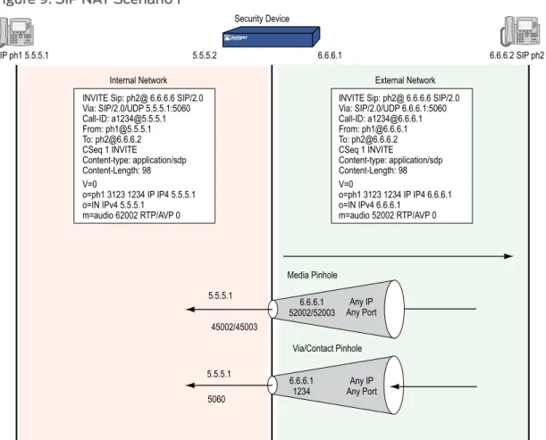
Figure 9: SIP NAT Scenario 1 . . . 31
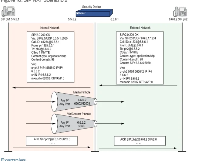
Figure 10: SIP NAT Scenario 2 . . . 32
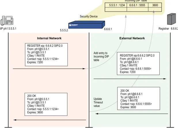
Figure 11: Incoming SIP . . . 33
Figure 12: Incoming Call with Interface DIP on ethernet3 Interface . . . 34
Figure 13: Incoming Call with DIP Pool . . . 36
Figure 14: Incoming Call with MIP . . . 38
Figure 15: Proxy in the Private Zone . . . 40
Figure 16: Proxy in the Public Zone . . . 42
Figure 17: Proxy in the DMZ . . . 45
Figure 18: Untrust Intrazone . . . 48
Figure 19: Trust Intrazone . . . 51
Figure 20: Full-Mesh VPN for SIP . . . 54
Figure 21: Priority-Level Settings . . . 63
Chapter 3 Media Gateway Control Protocol Application Layer Gateway . . . 65
Figure 22: Media Gateway in Subscribers’ Home . . . 72
Figure 23: ISP-Hosted Service . . . 74
Chapter 4 Skinny Client Control Protocol Application Layer Gateway . . . 79
Figure 24: Call Setup and Teardown . . . 84
Figure 25: Call Manager/TFTP Server in the Private Zone . . . 86
Figure 26: Call Manager/TFTP Server in the Untrust Zone . . . 88
Figure 27: Call Manager/TFTP Server in the DMZ . . . 90
Figure 28: Intrazone, Call Manager/TFTP Server in Trust Zone . . . 93
Figure 29: Intrazone, Call Manager/TFTP Server in Trust Zone . . . 97
Chapter 5 Apple iChat Application Layer Gateway . . . 107
Figure 31: AppleiChat Scenario 1—Users on Public and Private Networks . . . 109
Figure 32: AppleiChat Scenario 2—Intrazone Call Within a Private Network . . . 114
Part 1
VOIP
Chapter 2 Session Initiation Protocol Application Layer Gateway . . . 15
Table 1: Session Initiation Protocol Responses . . . 18
Table 2: Requesting Messages with NAT . . . 29
Chapter 3 Media Gateway Control Protocol Application Layer Gateway . . . 65
Table 3: MGCP Commands . . . 68
Chapter 4 Skinny Client Control Protocol Application Layer Gateway . . . 79
Table 4: SCCP Registration Messages . . . 82
Table 5: Station to Call Manager Messages . . . 84
Table 6: Call Manager to Station Messages . . . 85
Table 7: Call Manager 4.0 Messages and Post Skinny 6.2 . . . 85
Table 8: Call Manager to Station . . . 85
Chapter 5 Apple iChat Application Layer Gateway . . . 107
VOIPfocuses on the various methods available in ScreenOS to perform address translation. This guide contains the following chapters:
• “H.323 Application Layer Gateway” on page 3describes the H.323 protocol and provides examples of typical scenarios.
• “Session Initiation Protocol Application Layer Gateway” on page 15describes the Session Initiation Protocol (SIP) and shows how the SIP ALG processes calls in Route and Network Address Translation (NAT) modes. Examples of typical scenarios follow a summary of the SIP architecture.
• “Media Gateway Control Protocol Application Layer Gateway” on page 65presents an overview of the Media Gateway Control Protocol (MGCP) ALG and lists the firewall security features of the implementation. Examples of typical scenarios follow a summary of the MGCP architecture.
• “Skinny Client Control Protocol Application Layer Gateway” on page 79presents an overview of the Skinny Client Control Protocol (SCCP) ALG and lists the firewall security features of the implementation. Examples of typical scenarios follow a summary of the SCCP architecture.
• “Apple iChat Application Layer Gateway” on page 107presents an overview of the AppleiChat ALG and lists the firewall security features of the implementation. Examples of typical scenarios follow a summary of the AppleiChat architecture.
• Document Conventions on page xiii
• Document Feedback on page xvi
• Requesting Technical Support on page xvi
Document Conventions
This document uses the conventions described in the following sections: • Web User Interface Conventions on page xiii
• Command Line Interface Conventions on page xiv
• Naming Conventions and Character Types on page xiv
• Illustration Conventions on page xv
Web User Interface Conventions
The Web user interface (WebUI) contains a navigational path and configuration settings. To enter configuration settings, begin by clicking a menu item in the navigation tree on
the left side of the screen. As you proceed, your navigation path appears at the top of the screen, with each page separated by angle brackets.
The following example shows the WebUI path and parameters for defining an address: Policy > Policy Elements > Addresses > List > New: Enter the following, then clickOK:
Address Name: addr_1 IP Address/Domain Name:
IP/Netmask: (select), 10.2.2.5/32 Zone: Untrust
To open Online Help for configuration settings, click the question mark (?) in the upper right of the screen.
The navigation tree also provides a Help > Config Guide configuration page to help you configure security policies and Internet Protocol Security (IPSec). Select an option from the list, and follow the instructions on the page. Click the?character in the upper right for Online Help on the Config Guide.
Command Line Interface Conventions
The following conventions are used to present the syntax of command line interface (CLI) commands in text and examples.
In text, commands are inboldfacetype and variables are initalictype. In examples:
• Variables are initalictype.
• Anything inside square brackets [ ] is optional. • Anything inside braces { } is required.
• If there is more than one choice, each choice is separated by a pipe ( | ). For example, the following command means “set the management options for the ethernet1, the ethernet2,orthe ethernet3 interface”:
set interface { ethernet1 | ethernet2 | ethernet3 } manage
NOTE: When entering a keyword, you only have to type enough letters to identify the word uniquely. Typingset adm u whee j12fmt54will enter the commandset admin user wheezer j12fmt54. However, all the commands documented in this guide are presented in their entirety.
Naming Conventions and Character Types
ScreenOS employs the following conventions regarding the names of objects—such as addresses, admin users, auth servers, IKE gateways, virtual systems, VPN tunnels, and zones—defined in ScreenOS configurations:
• If a name string includes one or more spaces, the entire string must be enclosed within double quotes; for example:
• Any leading spaces or trailing text within a set of double quotes are trimmed; for example,“local LAN”becomes“local LAN”.
• Multiple consecutive spaces are treated as a single space.
• Name strings are case-sensitive, although many CLI keywords are case-insensitive. For example,“local LAN”is different from“local lan”.
ScreenOS supports the following character types:
• Single-byte character sets (SBCS) and multiple-byte character sets (MBCS). Examples of SBCS are ASCII, European, and Hebrew. Examples of MBCS—also referred to as double-byte character sets (DBCS)—are Chinese, Korean, and Japanese.
• ASCII characters from 32 (0x20 in hexadecimals) to 255 (0xff), except double quotes ( “ ), which have special significance as an indicator of the beginning or end of a name string that includes spaces.
NOTE: A console connection only supports SBCS. The WebUI supports both SBCS and MBCS, depending on the character sets that your browser supports.
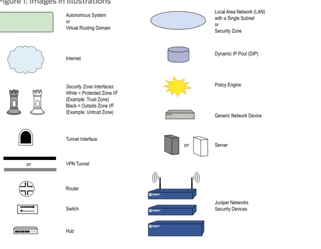
Illustration Conventions
Figure 1 on page xvishows the basic set of images used in illustrations throughout this volume.
Figure 1: Images in Illustrations
Document Feedback
If you find any errors or omissions in this document, contact Juniper Networks at [email protected].
Requesting Technical Support
Technical product support is available through the Juniper Networks Technical Assistance Center (JTAC). If you are a customer with an active J-Care or JNASC support contract, or are covered under warranty, and need postsales technical support, you can access our tools and resources online or open a case with JTAC.
• JTAC policies—For a complete understanding of our JTAC procedures and policies, review theJTAC User Guidelocated at
http://www.juniper.net/customers/support/downloads/710059.pdf. • Product warranties—For product warranty information, visit
http://www.juniper.net/support/warranty/.
• JTAC hours of operation—The JTAC centers have resources available 24 hours a day, 7 days a week, 365 days a year.
Self-Help Online Tools and Resources
For quick and easy problem resolution, Juniper Networks has designed an online self-service portal called the Customer Support Center (CSC) that provides you with the following features:
• Find CSC offerings—http://www.juniper.net/customers/support/ • Search for known bugs—Find product documentation—
http://www.juniper.net/techpubs/
• Find solutions and answer questions using our Knowledge Base—http://kb.juniper.net/ • Download the latest versions of software and review your release
notes—http://www.juniper.net/customers/csc/software/
• Search technical bulletins for relevant hardware and software notifications— http://www.juniper.net/alerts/
• Join and participate in the Juniper Networks Community Forum— http://www.juniper.net/company/communities/
• Open a case online in the CSC Case Manager— http://www.juniper.net/customers/cm/
• To verify service entitlement by product serial number, use our Serial Number Entitlement (SNE) Tool—
https://tools.juniper.net/SerialNumberEntitlementSearch/
Opening a Case with JTAC
You can open a case with JTAC on the Web or by telephone.
• Use the Case Manager tool in the CSC athttp://www.juniper.net/customers/cm/. • Call 1-888-314-JTAC (1-888-314-5822—toll free in USA, Canada, and Mexico). For international or direct-dial options in countries without toll-free numbers, visit us at http://www.juniper.net/customers/support/requesting-support/.
• H.323 Application Layer Gateway on page 3
• Session Initiation Protocol Application Layer Gateway on page 15
• Media Gateway Control Protocol Application Layer Gateway on page 65
• Skinny Client Control Protocol Application Layer Gateway on page 79
This chapter describes the H.323 protocol and provides examples for configuring the H.323 Application Layer Gateway (ALG) on a Juniper Networks security device. This chapter contains the following sections:
• Overview on page 3
• Alternate Gatekeeper on page 3
• Examples on page 4
Overview
The H.323 Application Layer Gateway (ALG) allows you secure voice over IP (VoIP) communication between terminal endpoints such as IP phones and multimedia devices. In such a telephony system, gatekeeper devices manage call registration, admission, and call status for VoIP calls. Gatekeepers can reside in the two different zones or in the same zone.
Figure 2: H.323 Protocol
NOTE: Illustrations in this chapter use IP phones for illustrative purposes, although it is possible to make configurations for other hosts that use VoIP, such as NetMeeting multimedia devices.
Alternate Gatekeeper
The H.323 ALG in ScreenOS supports the use of an alternate gatekeeper. All the IP end points must register with a gatekeeper through the Registration, Admission, and Status (RAS) protocol before they can attempt calls between them. During the registration process, the primary gatekeeper sends Gatekeeper Confirm (GCF) and Registration
Confirm (RCF) messages to the endpoint. These messages contain the list of available alternate gatekeepers.
The alternate gatekeeper provides high availability, redundancy and scalability for the IP end points. If the primary gatekeeper fails, IP-enabled phones and other multimedia devices registered with that gatekeeper are registered with the alternate gatekeeper. You can configure the primary and alternate gatekeepers in the Trust, Untrust, or DMZ zones.
NOTE: Currently, the Juniper Networks H.323 ALG supports the gatekeeper and the alternate gatekeeper in the same zone.
To use the alternate gatekeeper feature, you need to configure a security policy that allows the endpoint device to reach the alternate gatekeeper when the endpoint cannot reach the primary gatekeeper.
Examples
This section contains the following configuration scenarios: • Example: Gatekeeper in the Trust Zone on page 4
• Example: Gatekeeper in the Untrust Zone on page 5
• Example: Outgoing Calls with NAT on page 7
• Example: Incoming Calls with NAT on page 9
• Example: Gatekeeper in the Untrust Zone with NAT on page 12
Example: Gatekeeper in the Trust Zone
In the following example, you set up two policies that allow H.323 traffic to pass between IP phone hosts and a gatekeeper in the Trust zone, and an IP phone host (2.2.2.5) in the Untrust zone. In this example, the security device can be in either transparent mode or route mode. Both the Trust and Untrust security zones are in the trust-vr routing domain.
Figure 3: H.323 Gatekeeper in the Trust Zone
WebUI
1. Address
Address Name: IP_Phone IP Address/Domain Name:
IP/Netmask: (select), 2.2.2.5/32 Zone: Untrust
2. Policies
Policies > (From: Trust, To: Untrust) New: Enter the following, then clickOK: Source Address:
Address Book Entry: (select), Any Destination Address:
Address Book Entry: (select), IP_Phone Service: H.323
Action: Permit
Policies > (From: Untrust, To: Trust) New: Enter the following, then clickOK: Source Address:
Address Book Entry: (select), IP_Phone Destination Address:
Address Book Entry: (select), Any Service: H.323
Action: Permit
CLI
1. Address
set address untrust IP_Phone 2.2.2.5/32
2. Policies
set policy from trust to untrust any IP_Phone h.323 permit set policy from untrust to trust IP_Phone any h.323 permit save
Example: Gatekeeper in the Untrust Zone
Because transparent and route modes do not require address mapping of any kind, security device configuration for a gatekeeper in the Untrust zone is usually identical to the configuration for a gatekeeper in the Trust zone.
In the following example, you set up two policies to allow H.323 traffic to pass between IP phone hosts in the Trust zone, and the IP phone at IP address 2.2.2.5 (and the gatekeeper) in the Untrust zone. The device can be in transparent or route mode. Both the Trust and Untrust security zones are in the trust-vr routing domain.
WebUI
1. Addresses
Policy > Policy Elements > Addresses > List > New: Enter the following, then clickOK: Address Name: IP_Phone
IP Address/Domain Name: IP/Netmask: (select), 2.2.2.5/32 Zone: Untrust
Policy > Policy Elements > Addresses > List > New: Enter the following, then clickOK: Address Name: Gatekeeper
IP Address/Domain Name: IP/Netmask: (select), 2.2.2.10/32 Zone: Untrust
2. Policies
Policies > (From: Trust, To: Untrust) New: Enter the following, then clickOK: Source Address:
Address Book Entry: (select), Any Destination Address:
Address Book Entry: (select), IP_Phone Service: H.323
Action: Permit
Policies > (From: Untrust, To: Trust) New: Enter the following, then clickOK: Source Address:
Address Book Entry: (select), IP_Phone Destination Address:
Address Book Entry: (select), Any Service: H.323
Action: Permit
Policies > (From: Trust, To: Untrust) New: Enter the following, then clickOK: Source Address:
Address Book Entry: (select), Any Destination Address:
Address Book Entry: (select), Gatekeeper Service: H.323
Action: Permit CLI
1. Addresses
set address untrust IP_Phone 2.2.2.5/32 set address untrust gatekeeper 2.2.2.10/32
2. Policies
set policy from trust to untrust any IP_Phone h.323 permit set policy from trust to untrust any gatekeeper h.323 permit set policy from untrust to trust IP_Phone any h.323 permit
set policy from untrust to trust gatekeeper any h.323 permit save
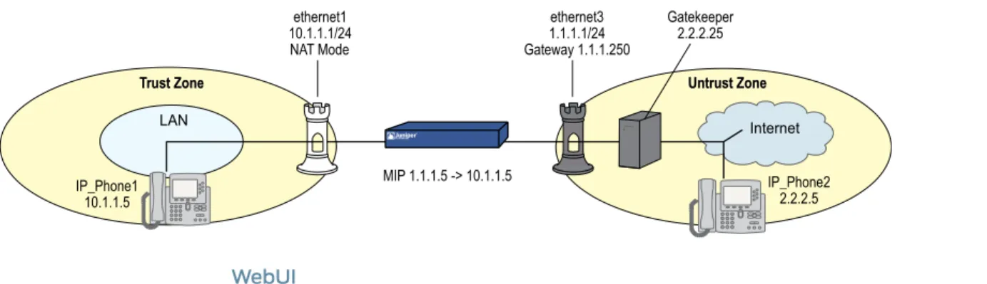
Example: Outgoing Calls with NAT
When the security device uses NAT (Network Address Translation), a gatekeeper or endpoint device in the Trust zone has a private address, and when it is in the Untrust zone it has a public address. When you set a security device in NAT mode, you must map a public IP address to each device that needs to receive incoming traffic with a private address.
In this example, the devices in the Trust zone include the endpoint host (10.1.1.5) and the gatekeeper device (10.1.1.25). IP_Phone2 (2.2.2.5) is in the Untrust zone. You configure the security device to allow traffic between the endpoint host IP_Phone1 and the gatekeeper in the Trust zone and the endpoint host IP_Phone2 in the Untrust zone. Both the Trust and Untrust security zones are in the trust-vr routing domain.
Figure 5: Network Address Translation—Outgoing Calls
WebUI
1. Interfaces
Network > Interfaces > Edit (for ethernet1): Enter the following, then clickApply: Zone Name: Trust
Static IP: (select this option when present) IP Address/Netmask: 10.1.1.1/24
Select the following, then clickOK: Interface Mode: NAT
Network > Interfaces > Edit (for ethernet3): Enter the following, then clickOK: Zone Name: Untrust
Static IP: (select this option when present) IP Address/Netmask: 1.1.1.1/24
2. Addresses
Policy > Policy Elements > Addresses > List > New: Enter the following, then clickOK: Address Name: IP_Phone1
IP Address/Domain Name: IP/Netmask: (select), 10.1.1.5/32 Zone: Trust
Address Name: Gatekeeper IP Address/Domain Name:
IP/Netmask: (select), 10.1.1.25/32 Zone: Trust
Policy > Policy Elements > Addresses > List > New: Enter the following, then clickOK: Address Name: IP_Phone2
IP Address/Domain Name: IP/Netmask: (select), 2.2.2.5/32 Zone: Untrust
3. Mapped IP Addresses
Network > Interfaces > Edit (for ethernet3) > MIP > New: Enter the following, then clickOK:
Mapped IP: 1.1.1.5
Netmask: 255.255.255.255 Host IP Address: 10.1.1.5
Host Virtual Router Name: trust-vr
Network > Interfaces > Edit (for ethernet3) > MIP > New: Enter the following, then clickOK:
Mapped IP: 1.1.1.25
Netmask: 255.255.255.255 Host IP Address: 10.1.1.25
Host Virtual Router Name: trust-vr
4. Route
Network > Routing > Destination > trust-vr New: Enter the following, then clickOK: Network Address/Netmask: 0.0.0.0/0
Gateway: (select) Interface: ethernet3
Gateway IP Address: 1.1.1.250
5. Policies
Policies > (From: Trust, To: Untrust) New: Enter the following, then clickOK: Source Address:
Address Book Entry: (select), IP_Phone1 Destination Address:
Address Book Entry: (select), IP_Phone2 Service: H.323
Action: Permit
Policies > (From: Trust, To: Untrust) New: Enter the following, then clickOK: Source Address:
Address Book Entry: (select), Gatekeeper Destination Address:
Address Book Entry: (select), IP_Phone2 Service: H.323
Action: Permit
Source Address:
Address Book Entry: (select), IP_Phone2 Destination Address:
Address Book Entry: (select), MIP(1.1.1.5) Service: H.323
Action: Permit
Policies 7gt; (From: Untrust, To: Trust) New: Enter the following, then clickOK: Source Address:
Address Book Entry: (select), IP_Phone2 Destination Address:
Address Book Entry: (select), MIP(1.1.1.25) Service: H.323
Action: Permit CLI
1. Interfaces
set interface ethernet1 zone trust set interface ethernet1 ip 10.1.1.1/24 set interface ethernet3 zone untrust set interface ethernet3 ip 1.1.1.1/24
2. Addresses
set address trust IP_Phone1 10.1.1.5/32 set address trust gatekeeper 10.1.1.25/32 set address untrust IP_Phone2 2.2.2.5/32
3. Mapped IP Addresses
set interface ethernet3 mip 1.1.1.5 host 10.1.1.5 set interface ethernet3 mip 1.1.1.25 host 10.1.1.25
4. Route
set vrouter trust-vr route 0.0.0.0/0 interface ethernet3 gateway 1.1.1.250
5. Policies
set policy from trust to untrust IP_Phone1 IP_Phone2 h.323 permit set policy from trust to untrust gatekeeper IP_Phone2 h.323 permit set policy from untrust to trust IP_Phone2 mip(1.1.1.5) h.323 permit set policy from untrust to trust IP_Phone2 mip (1.1.1.25) h.323 permit save
Example: Incoming Calls with NAT
In this example, you configure the security device to accept incoming calls over a NAT boundary. To do this, you can create a DIP address pool for dynamically allocating destination addresses. This differs from most configurations, where a DIP pool provides source addresses only.
Figure 6: Network Address Translation—Incoming Calls
The name of the DIP pool can be DIP(id_num) for a user-defined DIP, or DIP(interface) when the DIP pool uses the same address as an interface IP address. You can use such address entries as destination addresses in policies, together with the services H.323, SIP, or other VoIP (Voice-over-IP) protocols, to support incoming calls.
A single policy with a policy-based NAT (DIP ID 2) fails because of the twin-pair port limitations on the DIP pool. The policy segments the traffic so that they do not have more than 512 phones (the DIP limitation) on each DIP pool.
The following example uses DIP in an H.323 VoIP configuration. The keyword “ incoming” instructs the device to add the DIP and interface addresses to the global zone.
WebUI
1. Interfaces
Network > Interfaces > Edit (for ethernet1): Enter the following, then clickApply: Zone Name: Trust
Static IP: (select this option when present) IP Address/Netmask: 10.1.1.1/24
Enter the following, then clickOK: Interface Mode: NAT
Network > Interfaces > Edit (for ethernet3): Enter the following, then clickOK: Zone Name: Untrust
Static IP: (select this option when present) IP Address/Netmask: 1.1.1.1/24
2. DIP with Incoming NAT
Network > Interface > Edit (for ethernet3) > DIP > New: Enter the following, then click OK:
ID: 5
IP Address Range: (select), 1.1.1.12 ~ 1.1.1.150 Port Translation: (select)
In the same subnet as the interface IP or its secondary IPs: (select) Incoming NAT: (select)
3. Addresses
Policy > Policy Elements > Addresses > List > New (for Trust): Enter the following, then clickOK:
Address Name: IP_Phones1 IP Address/Domain Name:
IP/Netmask: (select), 10.1.1.5/24 Zone: Trust
Policy > Policy Elements > Addresses > List > New (for Untrust): Enter the following, then clickOK:
Address Name: IP_Phone2 IP Address/Domain Name:
IP/Netmask: (select), 2.2.2.5/32 Zone: Untrust
4. Policies
Policies > (From: Trust, To: Untrust) New: Enter the following, then clickOK: Source Address:
Address Book Entry: (select), IP_Phones1 Destination Address:
Address Book Entry: (select), Any Service: H.323
Action: Permit
Policies > (From: Untrust, To: Trust) New: Enter the following, then clickOK: Source Address:
Address Book Entry: (select), IP_Phone2 Destination Address:
Address Book Entry: (select), DIP(5) Service: H.323
Action: Permit CLI
1. Interfaces
set interface ethernet1 zone trust set interface ethernet1 ip 10.1.1.1/24 set interface ethernet3 zone untrust set interface ethernet3 ip 1.1.1.1/24
2. DIP with Incoming NAT
set interface ethernet3 dip 5 1.1.1.12 1.1.1.150 incoming
3. Addresses
set address trust IP_Phones1 10.1.1.5/24 set address untrust IP_Phone2 2.2.2.5/32
4. Policies
set policy from trust to untrust IP_Phones1 any h.323 nat src dip 5 permit set policy from untrust to trust IP_Phone2 dip(5) h.323 permit
Example: Gatekeeper in the Untrust Zone with NAT
In this example, the gatekeeper device (2.2.2.25) and host IP_Phone2 (2.2.2.5) are in the Untrust zone and host IP_Phone1 (10.1.1.5) is in the Trust zone. You configure the security device to allow traffic between host IP_Phone1 in the Trust zone and host IP_Phone2 (and the gatekeeper) in the Untrust zone. Both the Trust and Untrust security zones are in the trust-vr routing domain.
Figure 7: Gatekeeper in the Untrust Zone
WebUI
1. Interfaces
Network > Interfaces > Edit (for ethernet1): Enter the following, then clickApply: Zone Name: Trust
Static IP: (select this option when present) IP Address/Netmask: 10.1.1.1/24
Enter the following, then clickOK: Interface Mode: NAT
Network > Interfaces > Edit (for ethernet3): Enter the following, then clickOK: Zone Name: Untrust
Static IP: (select this option when present) IP Address/Netmask: 1.1.1.1/24
2. Addresses
Policy > Policy Elements > Addresses > List > New: Enter the following, then clickOK: Address Name: IP_Phone1
IP Address/Domain Name: IP/Netmask: (select), 10.1.1.5/32 Zone: Trust
Policy > Policy Elements > Addresses > List > New: Enter the following, then clickOK: Address Name: Gatekeeper
IP Address/Domain Name: IP/Netmask: (select), 2.2.2.25/32 Zone: Untrust
Policy > Policy Elements > Addresses > List > New: Enter the following, then clickOK: Address Name: IP_Phone2
IP/Netmask: (select), 2.2.2.5/32 Zone: Untrust
3. Mapped IP Address
Network > Interfaces > Edit (for ethernet3) > MIP > New: Enter the following, then clickOK:
Mapped IP: 1.1.1.5
Netmask: 255.255.255.255 Host IP Address: 10.1.1.5
4. Route
Network > Routing > Destination > trust-vr New: Enter the following, then clickOK: Network Address/Netmask: 0.0.0.0/0
Gateway: (select) Interface: ethernet3
Gateway IP Address: 1.1.1.250
5. Policies
Policies > (From: Trust, To: Untrust) New: Enter the following, then clickOK: Source Address:
Address Book Entry: (select), IP_Phone1 Destination Address:
Address Book Entry: (select), IP_Phone2 Service: H.323
Action: Permit
Policies > (From: Trust, To: Untrust) New: Enter the following, then clickOK: Source Address:
Address Book Entry: (select), IP_Phone1 Destination Address:
Address Book Entry: (select), Gatekeeper Service: H.323
Action: Permit
Policies > (From: Untrust, To: Trust) New: Enter the following, then clickOK: Source Address:
Address Book Entry: (select), IP_Phone2 Destination Address:
Address Book Entry: (select), MIP(1.1.1.5) Service: H.323
Action: Permit
Policies > (From: Untrust, To: Trust) New: Enter the following, then clickOK: Source Address:
Address Book Entry: (select), Gatekeeper Destination Address:
Address Book Entry: (select), MIP(1.1.1.5) Service: H.323
CLI
1. Interfaces
set interface ethernet1 zone trust set interface ethernet1 ip 10.1.1.1/24 set interface ethernet3 zone untrust set interface ethernet3 ip 1.1.1.1/24
2. Addresses
set address trust IP_Phone1 10.1.1.5/32 set address untrust gatekeeper 2.2.2.25/32 set address untrust IP_Phone2 2.2.2.5/32
3. Mapped IP Addresses
set interface ethernet3 mip 1.1.1.5 host 10.1.1.5
4. Route
set vrouter trust-vr route 0.0.0.0/0 interface ethernet3 gateway 1.1.1.250
5. Policies
set policy from trust to untrust IP_Phone1 IP_Phone2 h.323 permit set policy from trust to untrust IP_Phone1 gatekeeper h.323 permit set policy from untrust to trust IP_Phone2 mip(1.1.1.5) h.323 permit set policy from untrust to trust gatekeeper mip(1.1.1.5) h.323 permit save
Application Layer Gateway
This chapter describes the Session Initiation Protocol (SIP) Application Layer Gateway (ALG) and contains the following sections:
• Overview on page 15
• SIP with Network Address Translation on page 25
• Examples on page 32
Overview
Session Initiation Protocol (SIP) is an Internet Engineering Task Force (IETF)-standard protocol for initiating, modifying, and terminating multimedia sessions over the Internet. Such sessions might include conferencing, telephony, or multimedia, with features such as instant messaging and application-level mobility in network environments.
Juniper Networks security devices support SIP as a service and can screen SIP traffic, allowing and denying it based on a policy that you configure. SIP is a predefined service in ScreenOS and uses port 5060 as the destination port.
SIP’s primary function is to distribute session-description information and, during the session, to negotiate and modify the parameters of the session. SIP is also used to terminate a multimedia session.
Session-description information is included in INVITE and ACK messages and indicates the multimedia type of the session, for example, voice or video. Although SIP can use different description protocols to describe the session, the Juniper Networks SIP ALG supports only Session Description Protocol (SDP).
SDP provides information that a system can use to join a multimedia session. SDP might include information such as IP addresses, port numbers, times, and dates. Note that the IP address and port number in the SDP header (the “ c=” and “ m=” fields, respectively) are the address and port where the client wants to receive the media streams and not the IP address and port number from which the SIP request originates (although they can be the same). See“Session Description Protocol Sessions” on page 20for more information.
SIP messages consist of requests from a client to a server and responses to the requests from a server to a client with the purpose of establishing a session (or a call). A User Agent (UA) is an application that runs at the endpoints of the call and consists of two parts: the User Agent Client (UAC), which sends SIP requests on behalf of the user; and a User Agent Server (UAS), which listens to the responses and notifies the user when they arrive. Examples of UAs are SIP proxy servers and phones.
SIP Request Methods
The SIP transaction model includes a number of request and response messages, each of which contains a method field that denotes the purpose of the message. ScreenOS supports the following method types and response codes:
• INVITE—A user sends an INVITE request to invite another user to participate in a session. The body of an INVITE request may contain the description of the session. In NAT mode, the IP addresses in the Via:, From:, To:, Call-ID:, Contact:, Route:, and Record-Route: header fields are modified as shown inTable 2 on page 29.
• ACK—The user from whom the INVITE originated sends an ACK request to confirm reception of the final response to the INVITE request. If the original INVITE request did not contain the session description, the ACK request must include it. In NAT mode, the IP addresses in the Via:, From:, To:, Call-ID:, Contact:, Route:, and Record-Route: header fields are modified as shown inTable 2 on page 29.
• OPTIONS—Used by the User Agent (UA) to obtain information about the capabilities of the SIP proxy. A server responds with information about what methods, session description protocols, and message encoding it supports. In NAT mode, when the OPTIONS request is sent from a UA outside NAT to a proxy inside NAT, the SIP ALG translates the address in the Request-URI and the IP address in the To: field to the appropriate IP address of the internal client. When the UA is inside NAT and the proxy is outside NAT, the SIP ALG translates the From:, Via:, and Call-ID: fields as shown in
Table 2 on page 29.
• BYE—A user sends a BYE request to abandon a session. A BYE request from either user automatically terminates the session. In NAT mode, the IP addresses in the Via:, From:, To:, Call-ID:, Contact:, Route:, and Record-Route: header fields are modified as shown inTable 2 on page 29.
• CANCEL—A user can send a CANCEL request to cancel a pending INVITE request. A CANCEL request has no effect if the SIP server processing the INVITE had sent a final response for the INVITE before it received the CANCEL. In NAT mode, the IP addresses in the Via:, From:, To:, Call-ID:, Contact:, Route:, and Record-Route: header fields are modified as shown inTable 2 on page 29.
• REGISTER—A user sends a REGISTER request to a SIP registrar server to inform it of the current location of the user. A SIP registrar server records all the information it receives in REGISTER requests and makes this information available to any SIP server attempting to locate a user. In NAT mode, REGISTER requests are handled as follows:
• REGISTER requests from an external client to an internal registrar—When the SIP ALG receives the incoming REGISTER request it translates the IP address, if any, in the Request-URI. Incoming REGISTER messages are allowed only to a MIP or VIP address. No translation is needed for the outgoing response.
• REGISTER requests from an internal client to an external registrar—When the SIP ALG receives the outgoing REGISTER request it translates the IP addresses in the To:, From:, Via:, Call-ID:, and Contact: header fields. A backward translation is performed for the incoming response.
• Info—Used to communicate mid-session signaling information along the signaling path for the call. In NAT mode, the IP addresses in the Via:, From:, To:, Call-ID:, Contact:, Route:, and Record-Route: header fields are modified as shown inTable 2 on page 29. • Subscribe—Used to request current state and state updates from a remote node. In
NAT mode, the address in the Request-URI is changed to a private IP address if the messages is coming from the external network into the internal network. The IP addresses in Via:, From:, To:, Call-ID:, Contact:, Route:, and Record-Route: header fields are modified as shown in the table inTable 2 on page 29.
• Notify—Sent to inform subscribers of changes in state to which the subscriber has a subscription. In NAT mode, the IP address in the Request-URI: header field is changed to a private IP address if the message is coming from the external network into the internal network. The IP address in the Via:, From:, To:, Call-ID:, Contact:, Route:, and Record-Route: header fields are modified as shown inTable 2 on page 29.
• Refer—Used to refer the recipient (identified by the Request-URI) to a third party by the contact information provided in the request. In NAT mode, the IP address in the Request-URI is changed to a private IP address if the message is coming from the external network into the internal network. The IP addresses in the Via:, From:, To:, Call-ID:, Contact:, Route:, and Record-Route: header fields are modified as shown in
Table 2 on page 29.
For example, if user A in a private network refers user B, in a public network, to user C, who is also in the private network, the SIP ALG allocates a new IP address and port number for user C so that user C can be contacted by user B. If user C is registered with a registrar, however, its port mapping is stored in the ALG NAT table and is reused to perform the translation.
• Update—Used to open pinhole for new or updated SDP information. The Via:, From:, To:, Call-ID:, Contact:, Route:, and Record-Route: header fields are modified as shown inTable 2 on page 29.
• 1xx, 202, 2xx, 3xx, 4xx, 5xx, 6xx Response Codes—Used to indicate the status of a transaction. Header fields are modified as shown inTable 2 on page 29.
Classes of SIP Responses
SIP responses provide status information about SIP transactions and include a response code and a reason phrase. SIP responses are grouped into the following classes: • Informational (100 to 199)—Request received, continuing to process the request. • Success (200 to 299)—Action successfully received, understood, and accepted. • Redirection (300 to 399)—Further action required to complete the request.
• Client Error (400 to 499)—Request contains bad syntax or cannot be fulfilled at this server.
• Server Error (500 to 599)—Server failed to fulfill an apparently valid request. • Global Failure (600 to 699)—Request cannot be fulfilled at any server.
Table 1 on page 18provides a complete list of current SIP responses, all of which are supported on Juniper Networks security devices.
Table 1: Session Initiation Protocol Responses
Response Code-Reason Phrase Response Code-Reason Phrase
Response Code-Reason Phrase Class
181 Call is being forwarded 180 Ringing 100 Trying Informational 183 Session progress 182 Queued 202 Accepted 200 OK Success 302 Moved temporarily 301 Moved permanently 300 Multiple choices Redirection 380 Alternative service 305 Use proxy 402 Payment required 401 Unauthorized 400 Bad request Client Error
405 Method not allowed 404 Not found
403 Forbidden
408 Request time-out 407 Proxy authentication required
406 Not acceptable
411 Length required 410 Gone
409 Conflict
415 Unsupported media type 414 Request-URL too large
413 Request entity too large
481 Call leg/transaction does not exist
480 Temporarily not available 420 Bad extension
484 Address incomplete 483 Too many hops
482 Loop detected
487 Request canceled 486 Busy here
485 Ambiguous
488 Not acceptable here
502 Bad gateway 501 Not implemented
500 Server internal error Server Error
505 SIP version not supported 504 Gateway time-out
502 Service unavailable
604 Does not exist anywhere 603 Decline
600 Busy everywhere Global Failure
606 Not acceptable
SIP Application Layer Gateway
There are two types of SIP traffic, the signaling and the media stream. SIP signaling traffic consists of request and response messages between client and server and uses transport
protocols such as User Datagram Protocol (UDP) or Transmission Control Protocol (TCP). The media stream carries the data (audio data, for example) and uses Application Layer protocols such as Real Time Protocol (RTP) over UDP.
Juniper Networks security devices support SIP signaling messages on port 5060. You can simply create a policy that permits SIP service, and the security device filters SIP signaling traffic like any other type of traffic, permitting or denying it. The media stream, however, uses dynamically assigned port numbers that can change several times during the course of a call. Without fixed ports, it is impossible to create a static policy to control media traffic. In this case, the security device invokes the SIP ALG. The SIP ALG reads SIP messages and their SDP content and extracts the port-number information it needs to dynamically open pinholes and let the media stream traverse the security device.
NOTE: We refer to a pinhole as the limited opening of a port to allow exclusive traffic.
The SIP ALG monitors SIP transactions and dynamically creates and manages pinholes based on the information it extracts from these transactions. The Juniper Networks SIP ALG supports all SIP methods and responses (see“SIP Request Methods” on page 16
and“Classes of SIP Responses” on page 17). You can allow SIP transactions to traverse the Juniper Networks firewall by creating a static policy that permits SIP service. This policy enables the security device to intercept SIP traffic and do one of the following actions: permit or deny the traffic or enable the SIP ALG to open pinholes to pass the media stream. The SIP ALG needs to open pinholes only for the SIP requests and responses that contain media information (SDP). For SIP messages that do not contain SDP, the security device simply lets them through.
The SIP ALG intercepts SIP messages that contain SDP and, using a parser, extracts the information it requires to create pinholes. The SIP ALG examines the SDP portion of the packet, and a parser extracts information such as IP addresses and port numbers, which the SIP ALG records in a pinhole table. The SIP ALG uses the IP addresses and port numbers recorded in the pinhole table to open pinholes and allow media streams to traverse the security device.
The SIP ALG for IPv6 supports Netscreen Redundancy Protocol (NSRP).
NOTE: Juniper Networks security devices do not support encrypted SDP. If a security device receives a SIP message in which SDP is encrypted, the SIP ALG permits it through the firewall but generates a log message informing the user that it cannot process the packet. If SDP is encrypted, the SIP ALG cannot extract the information it needs from SDP to open pinholes. As a result, the media content that SDP describes cannot traverse the security device.
Session Description Protocol Sessions
An SDP session description is text-based and consists of a set of lines. It can contain session-level and media-level information. The session-level information applies to the whole session, while the media-level information applies to a particular media stream. An SDP session description always contains session-level information, which appears at the beginning of the description, and might contain media-level information, which comes after.
NOTE: In the SDP session description, the media-level information begins with the m= field.
Of the many fields in the SDP description, two are particularly useful to the SIP ALG because they contain Transport Layer information. The two fields are the following: • c=for connection information
This field can appear at the session or media level. It displays in this format: • c=<network type><address type><connection address>
Currently, the security device supports "IN" (for Internet) as the network type, "IP4 and IP6" as address types, and a unicast IP address or domain name as the destination (connection) IP address.
NOTE: Generally, the destination IP address can also be a multicast IP address, but ScreenOS does not currently support multicast with SIP.
If the destination IP address is a unicast IP address, the SIP ALG creates pinholes using the IP address and port numbers specified in the media description field m=.
• m=for media announcement
This field appears at the media level and contains the description of the media. It displays in this format:
m=<media><port><transport><fmt list>
Currently, the security device supports only “ audio” as the media and “ RTP” as the Application Layer transport protocol. The port number indicates the destination (not the origin) of the media stream. The format list (fmt list) provides information about the Application Layer protocol that the media uses.
In this release of ScreenOS, the security device opens ports only for RTP and RTCP. Every RTP session has a corresponding Real Time Control Protocol (RTCP) session. Therefore, whenever a media stream uses RTP, the SIP ALG must reserve ports (create pinholes) for both RTP and RTCP traffic. By default, the port number for RTCP is one higher than the RTP port number.
NOTE: Generally, the destination IP address can also be a multicast IP address, but ScreenOS does not currently support multicast with SIP.
Pinhole Creation
Both pinholes for the RTP and RTCP traffic share the same destination IP address. The IP address comes from the c= field in the SDP session description. Because the c= field can appear in either the session-level or media-level portion of the SDP session description, the parser determines the IP address based on the following rules (in accordance with SDP conventions):
• First, the SIP ALG parser verifies if there is a c= field containing an IP address in the media level. If there is one, the parser extracts that IP address, and the SIP ALG uses it to create a pinhole for the media.
• If there is no c= field in the media level, the SIP ALG parser extracts the IP address from the c= field in the session level, and the SIP ALG uses it to create a pinhole for the media. If the session description does not contain a c= field in either level, this indicates an error in the protocol stack, and the security device drops the packet and logs the event.
The following lists the information the SIP ALG needs to create a pinhole. This information comes from the SDP session description and parameters on the security device: • Protocol: UDP.
• Source IP: Unknown. • Source port: Unknown.
• Destination IP: The parser extracts the destination IP address from the c= field in the media or session level.
• Destination port: The parser extracts the destination port number for RTP from the m= field in the media level and calculates the destination port number for RTCP using the following formula:
RTP port number + one
• Lifetime: This value indicates the length of time (in seconds) during which a pinhole is open to allow a packet through. A packet must go through the pinhole before the lifetime expires. When the lifetime expires, the SIP ALG removes the pinhole. When a packet goes through the pinhole within the lifetime period, immediately afterwards the SIP ALG removes the pinhole for the direction from which the packet came.
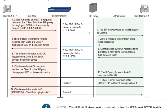
Figure 8 on page 22describes a call setup between two SIP clients and how the SIP ALG creates pinholes to allow RTP and RTCP traffic. The illustration assumes that the security device has a policy that permits SIP, thus opening port 5060 for SIP signaling messages.
Figure 8: SIP ALG Call Setup
NOTE: The SIP ALG does not create pinholes for RTP and RTCP traffic when the destination IP address is 0.0.0.0, which indicates that the session is on hold. To put a session on hold, during a telephone communication, for example, a user (User A) sends the other user (User B) a SIP message in which the destination IP address is 0.0.0.0. Doing so indicates to User B not to send any media until further notice. If User B sends media anyway, the security device drops the packets.
Session Inactivity Timeout
Typically a call ends when one of the clients sends a BYE or CANCEL request. The SIP ALG intercepts the BYE or CANCEL request and removes all media sessions for that call. There could be reasons or problems preventing clients in a call from sending BYE or CANCEL requests, for example, a power failure. In this case, the call might go on indefinitely, consuming resources on the security device. The inactivity-timeout feature helps the security device to monitor the liveliness of the call and terminate it if there is no activity for a specific period of time.
A call can have one or more voice channels. Each voice channel has two sessions (or two media streams), one for RTP and one for RTCP. When managing the sessions, the security device considers the sessions in each voice channel as one group. Settings such as the inactivity timeout apply to a group as opposed to each session.
• Signaling-inactivity timeout: This parameter indicates the maximum length of time (in seconds) a call can remain active without any SIP-signaling traffic. Each time a SIP-signaling message occurs within a call, this timeout resets. The default setting is 43200 seconds (12 hours).
• Media-inactivity timeout: This parameter indicates the maximum length of time (in seconds) a call can remain active without any media (RTP or RTCP) traffic within a group. Each time an RTP or RTCP packet occurs within a call, this timeout resets. The default setting is 120 seconds.
If either of these timeouts expires, the security device removes all sessions for this call from its table, thus terminating the call.
SIP Attack Protection
The ability of the SIP proxy server to process calls can be affected by repeat SIP INVITE requests, whether malicious or through client or server error, that it initially denied. To prevent the SIP proxy server from being overwhelmed by such requests, you can use the sip protect denycommand to configure the security device to monitor INVITE requests and proxy server replies to them. Thesip protect denycommand supports both IPv4 and IPv6 addresses. If a reply contains a 3xx, 4xx, or 5xx response code (see“Classes of SIP Responses” on page 17), the ALG stores the source IP address of the request and the IP address of the proxy server in a table. Subsequently, the security device checks all INVITE requests against this table and, for a configurable number of seconds (the default is 3), discards any packets that match entries in the table. You can also configure the security device to monitor INVITE request to a specific proxy server by specifying the destination IP address. SIP attack protection is configured globally.
Example: SIP Protect Deny
In this example, you configure the security device to protect a single SIP proxy server (1.1.1.3/24) from repeat SIP requests to which it has already denied service. Packets are dropped for a period of 5 seconds, after which the security device resumes forwarding INVITE requests from those sources.
WebUI
You must use the CLI to protect SIP proxy servers from being inundated by SIP messages.
CLI
set alg sip app-screen protect deny dst-ip 1.1.1.3/24 set alg sip protect deny timeout 5
save
Example: Signaling-Inactivity and Media-Inactivity Timeouts
In this example, you configure the signaling-inactivity timeout to 30,000 seconds and the media-inactivity timeout to 90 seconds.
WebUI
NOTE: You must use the CLI to set SIP-signaling and media-inactivity timeouts.
CLI
set alg sip signaling-inactivity-timeout 30000 set alg sip media-inactivity-timeout 90 save
Example: UDP Flooding Protection
You can protect the security device against UDP flooding by zone and destination address. In this example, you set a threshold of 80,000 per second for the number of UDP packets that can be received on IP address 1.1.1.5, in the Untrust zone, before the security device generates an alarm and drops subsequent packets for the remainder of that second.
NOTE: This example uses a general ScreenOS command and is not necessarily SIP-specific. For more information about UDP flood protection and how to determine effective settings, see UDP Flood.
WebUI
Security > Screening > Screen: Enter the following, then clickApply: Zone: Untrust
UDP Flood Protection (select)
> Destination IP: Enter the following, then click the Back arrow in your browser to return to the Screen configuration page:
Destination IP: 1.1.1.5 Threshold: 80000 Add: (select)
CLI
set zone untrust screen udp-flood dst-ip 1.1.1.5 threshold 80000 save
Example: SIP Connection Maximum
In this example, you prevent flood attacks on the SIP network from attackers in the Untrust zone by setting a maximum of 20 concurrent sessions from a single IP address. If the security device detects more than 20 connection attempts from the same IP address, it begins dropping subsequent attempts until the number of sessions drops below the specified maximum.
NOTE: This example uses a general ScreenOS command and is not necessarily SIP-specific. For more information about source-based session limits and how to determine effective settings, see Source Based and Destination Based Session
WebUI
Screening > Screen (Zone: Untrust): Enter the following, then clickOK: Source IP Based Session Limit: (select)
Threshold: 20 Sessions
CLI
set zone untrust screen limit-session source-ip-based 20 save
SIP with Network Address Translation
The Network Address Translation (NAT) protocol enables multiple hosts in a private subnet to share a single public IP address to access the Internet. For outgoing traffic, NAT replaces the private IP address of the host in the private subnet with the public IP address. For incoming traffic, the public IP address is converted back into the private address, and the message is routed to the appropriate host in the private subnet. Using NAT with the SIP service is more complicated because SIP messages contain IP addresses in the SIP headers as well as in the SIP body. The SIP headers contain information about the caller and the receiver, and the security device translates this information to hide it from the outside network. The SIP body contains the Session Description Protocol (SDP) information, which includes IP addresses and port numbers for transmission of the media. The security device translates SDP information for allocating resources to send and receive the media.
How IP addresses and port numbers in SIP messages are replaced depends on the direction of the message. For an outgoing message, the private IP address and port number of the client are replaced with the public IP address and port number of the Juniper Networks firewall. For an incoming message, the public address of the firewall is replaced with the private address of the client.
When an INVITE message is sent out across the firewall, the SIP ALG collects information from the message header into a call table, which it uses to forward subsequent messages to the correct end point. When a new message arrives, for example an ACK or 200 OK, the ALG compares the From:, To:, and Call-ID: fields against the call table to identify the call context of the message. If a new INVITE message arrives that matches the existing call, the ALG processes it as a REINVITE.
When a message containing SDP information arrives, the ALG allocates ports and creates a NAT mapping between them and the ports in the SDP. Because the SDP requires sequential ports for the Real Time Protocol (RTP) and Real Time Control Protocol (RTCP) channels, the ALG provides consecutive even-odd ports. If it is unable to find a pair of ports it discards the SIP message.
Outgoing Calls
When a SIP call is initiated with a SIP request message from the internal to the external network, NAT replaces the IP addresses and port numbers in the SDP and creates a binding to map the IP addresses and port numbers to the Juniper Networks firewall. Via:, Contact:, Route:, and Record-Route: SIP header fields, if present, are also bound to the firewall IP address. The ALG stores these mappings for use in retransmissions and for SIP response messages.
The SIP ALG then opens pinholes in the firewall to allow media through the security device on the dynamically assigned ports negotiated based on information in the SDP and the Via:, Contact:, and Record-Route: header fields. The pinholes also allow incoming packets to reach the Contact:, Via:, and Record-Route: IP addresses and ports. When processing return traffic, the ALG inserts the original Contact:, Via:, Route:, and Record-Route: SIP fields back into the packets.
Incoming Calls
Incoming calls are initiated from the public network to public Mapped IP (MIP) addresses or to interface IP addresses on the security device. MIPs are statically configured IP addresses that point to internal hosts; interface IP addresses are dynamically recorded by the ALG as it monitors REGISTER messages sent by internal hosts to the SIP registrar. (For more information, see“Examples” on page 32.) When the security device receives an incoming SIP packet, it sets up a session and forwards the payload of the packet to the SIP ALG.
The ALG examines the SIP request message (initially an INVITE) and, based on information in the SDP, opens gates for outgoing media. When a 200 OK response message arrives, the SIP ALG performs NAT on the IP addresses and ports and opens pinholes in the outbound direction. (The opened gates have a short time-to-live, and time out if a 200 OK response message is not received quickly.)
When a 200 OK response arrives, the SIP proxy examines the SDP information and reads the IP addresses and port numbers for each media session. The SIP ALG on the security device performs NAT on the addresses and port numbers, opens pinholes for outbound traffic, and refreshes the timeout for gates in the inbound direction.
When the ACK arrives for the 200 OK, it also passes through the SIP ALG. If the message contains SDP information, the SIP ALG ensures that the IP addresses and port numbers are not changed from the previous INVITE—if they are, the ALG deletes old pinholes and creates new pinholes to allow media to pass through. The ALG also monitors the Via:, Contact:, and Record-Route: SIP fields and opens new pinholes if it determines that these fields have changed.
Forwarded Calls
A forwarded call is when, for example, user A outside the network calls user B inside the network, and user B forwards the call to user C outside the network. The SIP ALG processes the INVITE from user A as a normal incoming call. But when the ALG examines the forwarded call from B to C outside the network and notices that B and C are reached
using the same interface, it does not open pinholes in the firewall, because media will flow directly between user A and user C.
Call Termination
The BYE message is used to terminate a call. When the security device receives a BYE message, it translates the header fields just as it does for any other message, But because a BYE message must be acknowledged by the receiver with a 200 OK, the ALG delays call teardown for five seconds to allow time for transmission of the 200 OK.
Call Re-INVITE Messages
Re-INVITE messages are used to add new media sessions to a call, and to removing existing media sessions. When new media sessions are added to a call, new pinholes are opened in the firewall and new address bindings created. The process is identical to the original call setup. When one or more media sessions are removed from a call, pinholes are closed and bindings released just as with a BYE message.
Call Session Timers
The SIP ALG uses the Session-Expires value to time out a session if a Re-INVITE or UPDATE message is not received. The ALG gets the Session-Expires value, if present, from the 200 OK response to the INVITE and uses this value for signaling timeout. If the ALG receives another INVITE before the session times out, it resets all timeout values to this new INVITE or to default values, and the process is repeated.
As a precautionary measure, the SIP ALG uses hard timeout values to set the maximum amount of time a call can exist. This ensures that the security device is protected in the event of the following:
• End systems crash during a call and a BYE message is not received. • Malicious users never send a BYE in an attempt to attack a SIP ALG.
• Poor implementations of sip proxy fail to process Record-Route and never send a BYE message.
• Network failures prevent a BYE message from being received.
Call Cancellation
Either party can cancel a call by sending a CANCEL message. Upon receiving a CANCEL message, the SIP ALG closes pinholes through the firewall—if any have been opened—and releases address bindings. Before releasing the resources, the ALG delays the control channel age-out for approximately five seconds to allow time for the final 200 OK to pass through. The call is terminated when the five second timeout expires, regardless of whether a 487 or non-200 response arrives.
Forking
Forking enables a SIP proxy to send a single INVITE message to multiple destinations simultaneously. When the multiple 200 OK response messages arrive for the single call, the SIP ALG parses but updates call information with the first 200 OK message it receives.
SIP Messages
The SIP message format consists of a SIP header section, and the SIP body. In request messages, the first line of the header section is the request line, which includes the method type, Request-URI, and protocol version. In response messages, the first line is the status line, which contains a status code. SIP headers contain IP addresses and port numbers used for signaling. The SIP body, separated from the header section by a blank line, is reserved for session description information, which is optional. Juniper Networks security devices currently support the Session Description Protocol (SDP) only. The SIP body contains IP addresses and port numbers used to transport the media.
In NAT mode, the security device translates information in the SIP headers to hide the information from the outside network. NAT is performed on SIP body information to allocate resources, that is, port numbers where the media is to be received.
SIP Headers
In the following sample SIP request message, NAT replaces the IP addresses in the header fields—shown in bold font—to hide them from the outside network.
INVITE [email protected]/2.0 Via: SIP/2.0/UDP10.150.20.3:5434 From: [email protected] To: [email protected] Call-ID: [email protected] Contact: [email protected]:5434 Route: <sip:[email protected]:5060> Record-Route: <sip:[email protected]:5060>
How IP address translation is performed depends on the type and direction of the message, which can be any of the following:
• Inbound request • Outbound response • Outbound request • Inbound response
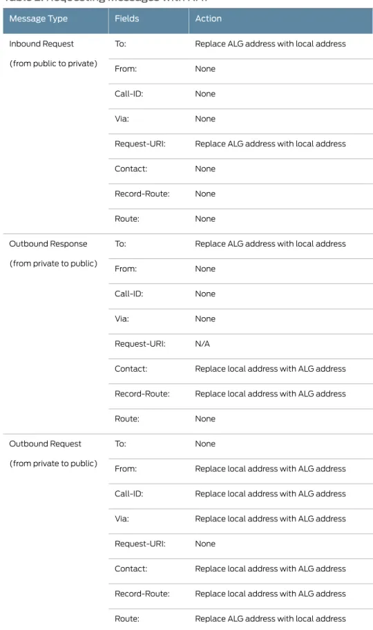
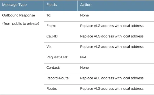
Table 2 on page 29shows how NAT is performed in each of these cases. Note that for several of the header fields the ALG must know more than just whether the messages comes from inside or outside the network. It must also know what client initiated the call, and whether the message is a request or response.
Table 2: Requesting Messages with NAT
Action Fields
Message Type
Replace ALG address with local address To:
Inbound Request
(from public to private)
None From: None Call-ID: None Via:
Replace ALG address with local address Request-URI: None Contact: None Record-Route: None Route:
Replace ALG address with local address To:
Outbound Response
(from private to public)
None From: None Call-ID: None Via: N/A Request-URI:
Replace local address with ALG address Contact:
Replace local address with ALG address Record-Route: None Route: None To: Outbound Request
(from private to public)
Replace local address with ALG address From:
Replace local address with ALG address Call-ID:
Replace local address with ALG address Via:
None Request-URI:
Replace local address with ALG address Contact:
Replace local address with ALG address Record-Route:
Replace ALG address with local address Route: