Introduction StartedGetting OverviewSystem ConfigurationSystem ConfigurationH.323 & SIP Registration Control Zones and Neighbors ProcessingCall TraversalFirewall Bandwidth Control Maintenance Appendices
Software version X1.0
D14049.01
July 2007
VIDEO
COMMUNICATION
SERVER
D 14049.01
ADMINISTRATOR
GUIDE
D 14049.01 07.2007
Introduction StartedGetting OverviewSystem ConfigurationSystem ConfigurationH.323 & SIP Registration Control Zones and Neighbors ProcessingCall TraversalFirewall Bandwidth Control Maintenance Appendices Introduction
What’s in this
ADMINISTRATOR
GUIDE?
VIDEO
COMMUNICATION
SERVER
Disclaimer, Copyrights and License Agreements
8
Safety Instructions and Approvals
9
Environmental Issues
0
Introduction
About the TANDBERG Video Communication Server ...12
Main Product Features ...12
Standard Features ...12
Optional Features ...12
About this Administrator Guide ...12
Getting Started
3
What’s in the Box? ...13Connecting the Cables ...13
Installation Site Preparations ...13
General Installation Precautions ...13
Powering on the VCS ... 14
Initial Configuration via Serial Cable ... 14
System Administrator Access...15
About Administrator Access ...15
Configuring Administrator Access ...15
Security Considerations ...15
Administrator Account Password ...15
Default Administrator Password ...15
Changing the Administrator Password ...15
Resetting the Administrator Password ...15
Session Timeout ...15
Root Account ...15
Using the Web Interface ... 16
Supported Browsers ... 16
Using the Command Line Interface (CLI) ... 17
Viewing System Overview
8
Viewing the Overview Page ...18Understanding the Overview Page ...18
System Configuration
9
System Administration Configuration ...19Configuring System Settings ...19
About the System Name ...19
About Admin Access settings ...19
Ethernet Configuration ...20
Configuring Ethernet Settings ...20
About Ethernet Speed ...20
IP Configuration ...21
Configuring IP Settings ...21
About IPv4 to IPv6 Gatewaying ...21
DNS Configuration ...22
Configuring DNS Settings ...22
About DNS Servers ...22
About the DNS Domain Name ...22
NTP Configuration ...23
Configuring NTP Settings ...23
About the NTP Server ...23
Setting the Time Zone ...23
SNMP Configuration ...24
Configuring SNMP Settings...24
About SNMP Settings ...24
External Manager Configuration ...25
Configuring External Manager Settings ...25
About the External Manager ...25
Backing up Configuration Settings ...26
TANDBERG VIDEO COMMUNICATION SERVER
3
Introduction StartedGetting OverviewSystem ConfigurationSystem ConfigurationH.323 & SIP Registration Control Zones and Neighbors ProcessingCall TraversalFirewall Bandwidth Control Maintenance Appendices Introduction
Logging
7
Logging Overview ... 27
About Logging ... 27
About Remote Logging ... 27
Enabling Remote Logging ... 27
About Event Log Levels ... 27
Setting the Event Log Level ... 27
Event Log ... 28
Viewing the Event Log ... 28
Event Log Format ... 28
Message Details Field ... 28
Events Logged at Level 1 ... 29
Events Logged at Level 2 ... 30
Events Logged at Level 3 ... 30
Event Data Fields ... 31
Working with H.33
33
H.323 Overview... 33About H.323 on the VCS ... 33
Using the VCS as an H.323 Gatekeeper ... 33
Configuring H.323 Ports ... 33
H.323 Endpoint Registration ... 33
Overview ... 33
Registration Conflict Mode ... 33
Auto Discover ... 33
Time to Live ... 33
Call Time to Live ... 33
Configuring H.323 ... 34
Working with SIP
35
SIP Overview ... 35About SIP on the VCS ... 35
Using the VCS as a SIP Registrar ... 35
Proxying Registration Requests ... 35
SIP Registration Expiry ... 35
Using the VCS as a SIP Proxy Server ... 35
SIP protocols and ports ... 35
Configuring SIP - Registrations, Protocols and Ports ... 36
Configuring SIP - Domains... 37
Interworking
38
Overview ... 38About Interworking ... 38
Configuring Interworking ... 38
Registration Control
39
Registration Overview ... 39Endpoint Registration ... 39
Registrations on a VCS Border Controller ... 39
MCU, Gateway and Content Server Registration ... 39
Finding a VCS with which to Register ... 40
SIP ... 40
H.323 ... 40
Authentication ... 41
About Authentication ... 41
Configuring Authentication ... 41
Authentication using an LDAP Server ... 42
Configuring the LDAP Server Directory ... 42
Securing the LDAP Connection with TLS ... 42
Alias Origin Setting ... 42
Configuring LDAP Server settings ... 43
Authentication using a Local Database ... 44
Configuring the Local Database ... 44
Registering Aliases ... 45
About Alias Registration ... 45
H.323 Alias Registration ... 45
SIP Alias Registration ... 45
Attempts to Register using an Existing Alias ... 45
H.323 ... 45
SIP ... 45
Allow and Deny Lists ... 46
About Allow and Deny Lists ... 46
Patterns and Pattern Types ... 46
Activating use of Allow or Deny Lists ... 46
Managing Entries in the Allow List ... 47
Managing Entries in the Deny List ... 48
Managing Zones, Neighbors and Alternates
49
Overview ... 49About your Video Communications Network... 49
Example ... 49
Local Zone and Subzones ... 50
About the Local Zone and its Subzones ... 50
Configuring the Local Zone and its Subzones ... 50
Zones ... 51
About Zones ... 51
ENUM Zone ... 51
DNS Zone ... 51
Traversal Client Zone... 51
Neighbor Zone ... 51
Traversal Server Zone ... 51
Default Zone ... 51
Adding Zones ... 52
Configuring Zones ... 52
Configuring Zones - All Types ... 53
Configuring Neighbor Zones ... 54
Configuring Traversal Client Zones ... 55
Configuring Traversal Server Zones ... 56
Configuring ENUM Zones ... 57
Configuring DNS Zones ... 57
About Alternates ... 58
Configuring Alternates ... 58
Setting up a Dial Plan ... 59
About Dial Plans ... 59
Flat Dial Plan ... 59
Structured Dial Plan ... 59
Hierarchical Dial Plan ... 59
TANDBERG VIDEO COMMUNICATION SERVER
ADMINISTRATOR GUIDE
D 14049.01 07.2007
Introduction StartedGetting OverviewSystem ConfigurationSystem ConfigurationH.323 & SIP Registration Control Zones and Neighbors ProcessingCall TraversalFirewall Bandwidth Control Maintenance Appendices Introduction
Call Processing
60
Locating a Destination Endpoint... 60
Overview ... 60
Process ... 60
Dialing by Address Types ... 61
About the Different Address Types ... 61
Dialing by IP Address ... 61
Dialing by H.323 ID or E.164 alias ... 61
Dialing by H.323 or SIP URI ... 61
Dialing by ENUM ... 61
Hop Counts ... 62
About Hop Counts ... 62
Configuring Hop Counts ... 62
Administrator Policy
63
Overview ... 63About Administrator Policy ... 63
Administrator Policy and Authentication ... 63
Enabling the use of Administrator Policy ... 64
Configuring Administrator Policy via the Web Interface ... 65
Configuring Administrator Policy via a CPL script ... 66
Uploading a CPL Script ... 66
About CPL XSD files ... 66
Downloading policy files ... 66
User Policy
67
About User Policy ... 67What is User Policy? ... 67
How are Devices Specified? ... 67
Process Overview ... 67
Who Must do What Before FindMe™ Can Be Used? ... 67
Recommendations When Deploying FindMe ... 67
User Policy Manager ... 67
Enabling User Policy on the VCS ... 68
Configuring User Policy Manager ... 68
Managing FindMe User Accounts ... 69
About User Accounts ... 69
Creating a New User Account ... 69
Changing a User Password ... 70
Viewing Existing User Account Settings ... 70
Managing FindMe User Accounts ... 71
Deleting a User Account ... 71
Using TANDBERG’s FindMe™
7
About your FindMe User Account ... 72About FindMe™... 72
FindMe User Accounts ... 72
Individual versus Group FindMe ... 72
Accessing the FindMe Configuration Page ... 72
Configuring your FindMe User Account... 73
Alias Searching and Transforming
74
Overview of Searches and Transforms ...74About Searches ...74
About Transforms ...74
Transforming an Alias Before Searching Locally ...74
About Local Alias Transforms ...74
Local Alias Transform Process ...74
If the Transformed Alias is Not Found Locally ...74
Configuring Local Alias Transforms ... 75
Zone Searching and Transforming ... 76
About Zone Searching ... 76
Mode ... 76
Priority ... 76
About Zone Transforms ... 76
Using Zone Searches and Transforms Together ... 76
Zone Search and Transform Process ... 76
Configuring Zone Searches and Transforms ... 77
Default Settings ... 77
Examples ... 78
Combining Match Types and Priorities ... 78
Never Query a Zone ... 78
Always Query a Zone, Never Apply Transforms ... 78
Filter Queries to a Zone Without Transforming ... 79
Changing the Prefix or Suffix Before Querying ... 79
Query a Zone for Both Original and Transformed Alias ... 80
Query a Zone for Two or More Transformed Aliases ... 80
URI Dialing
8
URI Dialing Overview ... 81About URI Dialing ... 81
URI Resolution Process via DNS ... 81
Enabling URI Dialing via the VCS ... 81
Outgoing Calls ... 81
Incoming Calls ... 81
Firewall Traversal Calls ... 81
URI Dialing for Outgoing Calls ... 82
Process ... 82
Configuring Matches for DNS Zones ... 82
Adding and Configuring DNS Zones ... 83
Configuring DNS Servers ... 84
URI Dialing for Incoming Calls ... 85
Types of DNS Records Required ... 85
Process ... 85
SRV Record Format ... 85
Configuring H.323 SRV Records ... 85
Location SRV Records ... 85
Call SRV Records ... 85
Configuring SIP SRV Records ... 85
Example DNS Record Configuration ... 86
URI Dialing and Firewall Traversal ... 86
Recommended Configuration ... 86
TANDBERG VIDEO COMMUNICATION SERVER
ADMINISTRATOR GUIDE
Table of Contents
5
Introduction StartedGetting OverviewSystem ConfigurationSystem ConfigurationH.323 & SIP Registration Control Zones and Neighbors ProcessingCall TraversalFirewall Bandwidth Control Maintenance Appendices Introduction
ENUM Dialing
87
ENUM Dialing Overview ... 87
About ENUM Dialing ... 87
ENUM Process ... 87
Enabling ENUM Dialing ... 87
Outgoing Calls ... 87
Incoming Calls ... 87
ENUM Dialing for Outgoing Calls ... 88
Prerequisites ... 88
Process ... 88
Example ... 88
Configuring Matches for ENUM Zones ... 89
Example ... 89
Configuring Transforms for ENUM Zones ... 89
Example ... 89
Configuring ENUM Zones ... 90
Configuring DNS Servers ... 91
ENUM Dialing for Incoming Calls ... 92
Prerequisites ... 92
About DNS Domains for ENUM ... 92
Configuring DNS NAPTR Records ... 92
Example ... 92
Calls to and from Unregistered Endpoints
93
About Unregistered Endpoints ... 93Calls to an Unregistered Endpoint ... 93
Overview ... 93
Configuration ... 93
Calls from an Unregistered Endpoint ... 93
Recommended Configuration for Firewall Traversal ... 93
Fallback Alias
94
Fallback Alias ... 94Overview ... 94
Configuration ... 94
Example Use of a Fallback Alias ... 94
Disconnecting calls
95
Overview ... 95About the Call Control API ... 95
Identifying a Particular Call ... 95
Call ID Number ... 95
Call Serial Number ... 95
Obtaining the Call ID/Serial Number ... 95
Disconnecting a Call via the Web Interface ... 96
Disconnecting a Call via the CLI ... 96
Issues when Disconnecting SIP Calls ... 96
Firewall Traversal
97
Firewall Traversal Overview ... 97About Firewall Traversal ... 97
VCS and Firewall Traversal ... 97
VCS as a Firewall Traversal Client ... 97
VCS as a Firewall Traversal Server ... 97
Firewall Traversal Protocols and Ports ... 98
Overview ... 98
Process ... 98
Ports for Initial Connections from Traversal Clients ... 98
H.323 Firewall Traversal Protocols ... 98
Assent Ports ... 98
H.460.18/19 Ports ... 98
SIP Ports ... 98
Ports for Connections out to the Public Internet ... 99
STUN Ports ... 99
Firewall Configuration ... 99
Firewall Traversal and Authentication... 100
Overview ... 100
Client Type and Client Settings ... 100
Server Type and Server Settings ... 100
Configuring the VCS as a Traversal Client ... 101
Overview ... 101
Adding a New Traversal Client Zone ... 101
Configuring a Traversal Client Zone ... 102
Configuring the VCS as a Traversal Server ... 103
Overview ... 103
Adding a New Traversal Server Zone ... 103
Configuring a Traversal Server Zone ... 104
Configuring Traversal for Endpoints ... 105
Configuring Traversal Server Ports ... 106
STUN Services ... 107
About STUN ... 107
About ICE ... 107
STUN Binding Discovery ... 107
STUN Relay ... 107
Configuring STUN Services ... 108
Bandwidth Control
09
Overview ... 109About Bandwidth Control ... 109
Example Network Deployment ... 109
Subzones ... 110
About Subzones ... 110
About the Default Subzone ... 110
Specifying the IP Address Range of a Subzone ... 110
About the Traversal Subzone ... 110
Default Settings ... 110
Traversal Calls ... 110
Bandwidth Consumption of Traversal Calls ... 110
Creating a Subzone ... 111
Configuring a Subzone ... 112
Applying Bandwidth Limitations to Subzones ... 113
Types of Limitations ... 113
How Different Bandwidth Limitations are Managed ... 113
About Pipes ... 114
Creating Pipes ... 114
Editing Pipes ... 115
About Links ... 116
Default Links ... 116
Creating Links ... 116
Editing Links ... 117
TANDBERG VIDEO COMMUNICATION SERVER
ADMINISTRATOR GUIDE
D 14049.01 07.2007
Introduction StartedGetting OverviewSystem ConfigurationSystem ConfigurationH.323 & SIP Registration Control Zones and Neighbors ProcessingCall TraversalFirewall Bandwidth Control Maintenance Appendices Introduction
Applying Pipes to Links ... 118
One Pipe, One Link ... 118
One Pipe, Two or More Links ... 118
Two Pipes, One Link ... 118
Default Links... 118
About Default Links ... 118
Pre-Configured Links ... 118
Automatically Created Links ... 118
Default Call Bandwidth, Insufficient Bandwidth and Downspeeding ... 119
About the Default Call Bandwidth ... 119
About Downspeeding ... 119
Configuring the Default Call Bandwidth and Downspeeding . 119 Bandwidth Control Examples ... 120
Example Without a Firewall ... 120
Example With a Firewall ... 121
VCS Border Controller Subzone Configuration ... 121
Enterprise VCS Subzone Configuration ... 121
Maintenance
Upgrading Software ... 122About Upgrading the VCS Software ... 122
Prerequisites ... 122
Backing up the Existing Configuration Before Upgrading . 122 Upgrading Using SCP/PSCP ... 122
Upgrading via the Web Interface ... 123
Option Keys ... 124
About Adding Extra Options ... 124
Adding Options via the CLI ... 124
Adding Options via the Web Interface ... 125
Security ... 126
About Security ... 126
Enabling Security ... 126
Passwords ... 127
Changing the Administrator Password ... 127
System Snapshot ... 127
About the System Snapshot ... 127
Creating a System Snapshot ... 127
Restarting ... 128
About Restarting ... 128
Shutting Down ... 128
About Shutting Down ... 128
Command Reference - xConfiguration
9
Command Reference - xCommand
49
Command Reference - xStatus
57
CPL Reference
70
Overview ...170CPL Examples ...174
Call Screening of Authenticated Users ...174
Call Screening Based on Alias ...174
Call Screening Based on Domain ...175
Change of Domain Name ...175
Allow Calls from Locally Registered Endpoints Only ...176
Block Calls from Default Zone and Default Subzone ...176
Restricting Access to a Local Gateway ... 177
Regular Expression Reference
78
About Regular Expressions ...178DNS Configuration
79
Overview ...179Verifying the SRV Record ...179
Microsoft DNS Server ...179
BIND 8 & 9 ...179
LDAP Configuration
80
About the LDAP Databases ... 180Downloading the H.350 schemas ... 180
Microsoft Active Directory ... 181
Prerequisites ... 181
Installing the H.350 Schemas ... 181
Adding H.350 Objects ... 181
Securing with TLS ... 181
OpenLDAP... 182
Prerequisites ... 182
Installing the H.350 Schemas ... 182
Adding H.350 Objects ... 182
Securing with TLS ... 182
Bibliography
83
Glossary
84
TANDBERG VIDEO COMMUNICATION SERVER
ADMINISTRATOR GUIDE
Table of Contents
7
Introduction StartedGetting OverviewSystem ConfigurationSystem ConfigurationH.323 & SIP Registration Control Zones and Neighbors ProcessingCall TraversalFirewall Bandwidth Control Maintenance Appendices Introduction
All rights reserved. This document contains information that
is proprietary to TANDBERG. No part of this publication may
be reproduced, stored in a retrieval system, or transmitted,
in any form, or by any means, electronically, mechanically,
by photocopying, or otherwise, without the prior written
permission of TANDBERG. Nationally and internationally
recognized trademarks and trade names are the property of
their respective holders and are hereby acknowledged.
COPYRIGHT © 2007, TANDBERG
Philip Pedersens vei 22
1366 Lysaker, Norway
Tel:
+47 67 125 125
Fax: +47 67 125 234
e-mail: [email protected]
Trademarks and Copyright
TANDBERG VIDEO COMMUNICATION SERVER
ADMINISTRATOR GUIDE
D 14049.01 07.2007
Introduction StartedGetting OverviewSystem ConfigurationSystem ConfigurationH.323 & SIP Registration Control Zones and Neighbors ProcessingCall TraversalFirewall Bandwidth Control Maintenance Appendices Introduction
The information in this document is furnished for informational purposes only, is subject to change without prior notice, and should not be construed as a commitment by TANDBERG. TANDBERG reserves the right to amend any of the information given in this document in order to take account of new developments.
Every effort has been made to supply complete and accurate information, however, TANDBERG assumes no responsibility or liability for any errors or inaccuracies that may appear in this document, nor for any infringements of patents or other rights of third parties resulting from its use. No license is granted under any patents or patent rights of TANDBERG.
TANDBERG technology described in this manual is protected by one or more of the following:
U.S. Patent Nos. 5,600,646 5,768,263 5,838,664 5,991,277 6,584,077 6,590,603 7,010,119 7,034,860
U.S. Patent Application Nos. 10/332.785
10/432.468 11/008.150 Other patents pending.
•
•
•
•
•
•
•
•
•
•
•
Disclaimer
Copyright Notice
Patent Information
Disclaimer, Copyrights and License Agreements
Tandberg software in this product is protected under the copyright and patent laws.
Copyright © 2007 Tandberg Telecom AS. All rights reserved. Patents pending in the U.S.
This product includes copyrighted software licensed from others. A list of the copyright notices and the terms and conditions of use can be found at:
http://www.tandberg.com/collateral/documentation/User_ Manuals/TANDBERG VCS EULA.pdf
and
http://www.tandberg.com/collateral/documentation/User_ Manuals/TANDBERG VCS Copyrights.pdf.
IMPORTANT: USE OF THIS PRODUCT IS SUBJECT IN ALL CASES TO THE COPYRIGHT RIGHTS AND THE TERMS AND CONDITIONS OF USE REFERRED TO ABOVE. USE OF THIS PRODUCT CONSTITUTES AGREEMENT TO SUCH TERMS AND CONDITIONS.
TANDBERG VIDEO COMMUNICATION SERVER
9
Introduction StartedGetting OverviewSystem ConfigurationSystem ConfigurationH.323 & SIP Registration Control Zones and Neighbors ProcessingCall TraversalFirewall Bandwidth Control Maintenance Appendices Introduction
For your protection please read these safety instructions completely before you connect the equipment to the power source. Carefully observe all warnings, precautions and
instructions both on the apparatus and in these operating instructions. Retain this manual for future reference.
Water and Moisture
Do not operate the apparatus under or near water – for example near a bathtub, kitchen sink, or laundry tub, in a wet basement, near a swimming pool or in other areas with high humidity.
Never install jacks for communication cables in wet locations unless the jack is specifically designed for wet locations. Do not touch the product with wet hands.
Cleaning
Unplug the apparatus from communication lines, mains power-outlet or any power source before cleaning or polishing. Do not use liquid cleaners or aerosol cleaners. Use a lint-free cloth lightly moistened with water for cleaning the exterior of the apparatus.
Ventilation
Do not block any of the ventilation openings of the apparatus. Never cover the slots and openings with a cloth or other material. Never install the apparatus near heat sources such as radiators, heat registers, stoves, or other apparatus (including amplifiers) that produce heat.
Do not place the product in direct sunlight or close to a surface directly heated by the sun.
•
•
•
•
•
•
•
Lightning
Never use this apparatus, or connect/ disconnect communication cables or power cables during lightning storms.
Dust
Do not operate the apparatus in areas with high concentration of dust.
Vibration
Do not operate the apparatus in areas with vibration or place it on an unstable surface.
Power Connection and Hazardous
Voltage
The product may have hazardous voltage inside. Never attempt to open this product, or any peripherals connected to the product, where this action requires a tool.
This product should always be powered from an earthed power outlet.
Never connect attached power supply cord to other products.
In case any parts of the product has visual damage never attempt to connect mains power, or any other power source, before consulting service personnel
The plug connecting the power cord to the product/power supply serves as the main disconnect device for this equipment. The power cord must always be easily accessible.
Route the power cord so as to avoid it being walked on or pinched by items placed upon or against it. Pay particular attention to the plugs, receptacles and the point where the cord exits from the apparatus.
Do not tug the power cord.
•
•
•
•
•
•
•
If the provided plug does not fit into your outlet, consult an electrician.
Never install cables, or any peripherals, without first unplugging the device from it's power source.
Servicing
Do not attempt to service the apparatus yourself as opening or removing covers may expose you to dangerous voltages or other hazards, and will void the warranty. Refer all servicing to qualified service personnel. Unplug the apparatus from its power source and refer servicing to qualified personnel under the following conditions:
If the power cord or plug is damaged or frayed.
If liquid has been spilled into the apparatus.
If objects have fallen into the apparatus. If the apparatus has been exposed to rain or moisture
If the apparatus has been subjected to excessive shock by being dropped. If the cabinet has been damaged. If the apparatus seems to be overheated. If the apparatus emits smoke or
abnormal odor.
If the apparatus fails to operate in accordance with the operating instructions.
Accessories
Use only accessories specified by the manufacturer, or sold with the apparatus.
•
•
•
•
•
•
•
•
•
•
•
•
•
Safety Instructions and Approvals
Electromagnetic Compatibility (EMC)
This is a Class A product. In a domestic environment this product may cause radio interference in which case the user may be required to take adequate measures.EC Declaration of Conformity
Manufacturer: TANDBERG Telecom AS Product Name: TANDBERG VideoCommunication Server Type Number: TTC2-04
Description: Network unit
This product complies with Commission Directives:
LVD 73/23/EEC EMC 89/336/EEC
This product complies with harmonized Standards:
EN 60950-1 : 2001, A11 EN 55022 : 1994, A1/A2 EN 55024 : 1998, A1/A2 EN 61000-3-2 : 2000 EN 61000-3-3 : 1995, A1
Technical Construction File No.: X13526 Year which the CE mark was affixed: 2007 For an official, signed version of this
document, or details regarding documentation from the technical construction file, please contact TANDBERG.
JATE Approval (Japan only)
This unit must be connected to the public internet via a router/switch that has JATE approval.
•
•
•
•
•
•
•
Approvals
Safety Instructions
TANDBERG VIDEO COMMUNICATION SERVER
ADMINISTRATOR GUIDE
D 14049.01 07.2007
Introduction StartedGetting OverviewSystem ConfigurationSystem ConfigurationH.323 & SIP Registration Control Zones and Neighbors ProcessingCall TraversalFirewall Bandwidth Control Maintenance Appendices Introduction
Thank you for buying a product which contributes to a reduction in pollution, and thereby helps save the environment. Our products reduce the need for travel and transport and thereby reduce pollution. Our products have either none or few consumable parts (chemicals, toner, gas, paper). Our products are low energy consuming products.
TANDBERG’s Environmental Policy
Environmental stewardship is important to TANDBERG’s culture. As a global company with strong corporate values, TANDBERG is committed to following international environmental legislation and designing technologies that help companies, individuals and communities creatively address environmental challenges. TANDBERG’s environmental objectives are to:
Develop products that reduce energy consumption, CO2
emissions, and traffic congestion
Provide products and services that improve quality of life for our customers
Produce products that can be recycled or disposed of safely at the end of product life
Comply with all relevant environmental legislation.
•
•
•
•
European Environmental Directives
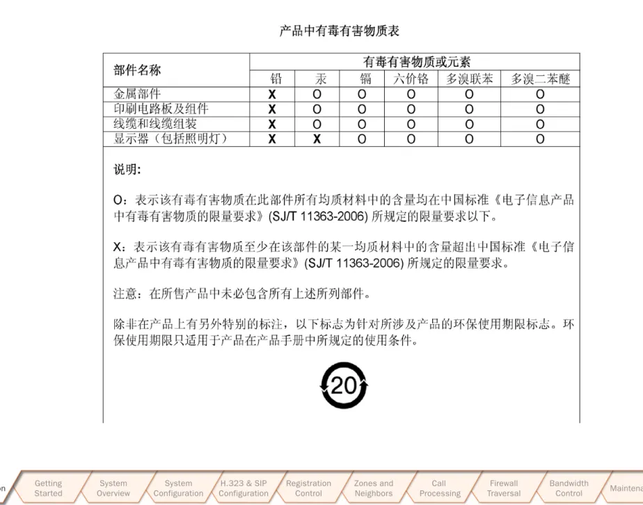
As a manufacturer of electrical and electronic equipment TANDBERG is responsible for compliance with the requirements in the European Directives 2002/96/EC (WEEE) and 2002/95/EC (RoHS).
The primary aim of the WEEE Directive and RoHS Directive is to reduce the impact of disposal of electrical and electronic equipment at end-of-life. The WEEE Directive aims to reduce the amount of WEEE sent for disposal to landfill or incineration by requiring producers to arrange for collection and recycling. The RoHS Directive bans the use of certain heavy metals and brominated flame retardants to reduce the environmental impact of WEEE which is landfilled or incinerated.
TANDBERG has implemented necessary process changes to comply with the European RoHS Directive (2002/95/EC) and the European WEEE Directive (2002/96/EC).
Waste Handling
In order to avoid the dissemination of hazardous substances in our environment and to diminish the pressure on natural resources, we encourage you to use the appropriate take-back systems in your area. Those systems will reuse or recycle most of the materials of your end of life equipment in a sound way.
TANDBERG products put on the market after August 2005 are marked with a crossed-out wheelie bin symbol that invites you to use those take-back systems.
Please contact your local supplier, the regional waste administration, or http://www.tandberg.com/recycling if you need more information on the collection and recycling system in your area.
Information for Recyclers
As part of compliance with the European WEEE Directive, TANDBERG provides recycling information on request for all types of new equipment put on the market in Europe after August 13th 2005.
Please contact TANDBERG and provide the following details for the product for which you would like to receive recycling information:
Model number of TANDBERG product Your company’s name
Contact name Address
Telephone number E-mail.
Digital User Guides
TANDBERG is pleased to announce that we have replaced the printed versions of our User Guides with a digital CD version. Instead of a range of different user manuals, there is now one CD – which can be used with all TANDBERG products – in a variety of languages. The environmental benefits of this are significant. The CDs are recyclable and the savings on paper are huge. A simple web-based search feature helps you directly access the information you need. In addition, the TANDBERG video systems now have an intuitive on-page help function, which provides a range of useful features and tips. The contents of the CD can still be printed locally, whenever needed.
•
•
•
•
•
•
TANDBERG VIDEO COMMUNICATION SERVER
ADMINISTRATOR GUIDE
Environmental Issues
Introduction StartedGetting OverviewSystem ConfigurationSystem ConfigurationH.323 & SIP Registration Control Zones and Neighbors ProcessingCall TraversalFirewall Bandwidth Control Maintenance Appendices Introduction
12
TANDBERG
CONTENT SERVER
USER GUIDE
Table of
Contents
What’s New in
this Version?
Trademark/
Licenses
Environmental
Safety/
Introduction
Installation
Quick Setup
Operation
Administrator
Settings
Conference
Setup
Conferences
View
Appendices
D 13898.04
DECEMBER 2006
TANDBERG VIDEO COMMUNICATION SERVER
ADMINISTRATOR GUIDE
D 14049.01 07.2007
Introduction StartedGetting OverviewSystem ConfigurationSystem ConfigurationH.323 & SIP Registration Control Zones and Neighbors ProcessingCall TraversalFirewall Bandwidth Control Maintenance Appendices Introduction
This Administrator Guide is provided to help you make the best use of your TANDBERG VCS.
Your approach to this documentation depends on what you want to do and how much you already know.
The Administrator Guide has been divided into several sections, each providing different information. In some places information is duplicated between sections to let you have all the relevant information in one place.
This document does not have an index - this is intentional. If the Table of Contents does not direct you to the information you need, you can use the Find function in Adobe Reader to search the text for keywords.
Note that the Administrator Guide describes a fully equipped version. Your version may not have all the described extensions installed.
Our main objective with this Guide is to address your goals and needs. Please let us know how well we succeeded!
The TANDBERG Video Communication Server (VCS) is a key component of your video communications network. It allows you to manage endpoint registrations and calls, and control the bandwidth being used within your network. The VCS also offers advanced call policy that allows you to accept, reject and re-route calls, and can optionally include TANDBERG’s FindMe™, which allows users to have a single alias on which they can be contacted regardless of location,
The VCS forms part of TANDBERG’s Expressway™ firewall traversal solution, allowing you to securely connect to other video networks and equipment from your secured private network.
The VCS also acts as a gateway between SIP and H.323 protocols, and between IPv4 and IPv6, allowing you to make the most use of your existing video communications investment.
About this Administrator Guide
About the TANDBERG Video Communication Server
Main Product Features
Standard Features
H.323 gatekeeper SIP Proxy/Registrar
SIP and H.323 support, including SIP/H.323 gatewaying for locally registered endpoints
IPv4 and IPv6 support, including IPv4/IPv6 gatewaying Bandwidth management on both a per-call and a total usage basis, configurable separately for calls within the local subzones and to neighboring systems and zones Automatic downspeeding option for calls that exceed the available bandwidth
URI and ENUM dialing via DNS, enabling global connectivity Up to 2500 registrations
Up to 500 non-traversal calls Up to 100 traversal calls Up to 200 neighboring zones
Flexible zone configuration with prefix, suffix and regex support
Can function as a stand-alone VCS or be neighbored with other systems such as VCSs, Border Controllers, gatekeepers and SIP proxies
•
•
•
•
•
•
•
•
•
•
•
•
•
Supports up to 5 Alternate VCSs for redundancy purposes Optional endpoint authentication
Control over which endpoints are allowed to register Administrator Policy including support for CPL Embedded setup wizard via a serial port for initial configuration
System administration via a web interface or RS-232, Telnet, SSH, and HTTPS
Can be managed with TANDBERG Management Suite 11.8 or newer
Optional Features
Firewall traversal server functionality, allowing secure traversal of any firewall or NAT
Registration of traversal-enabled endpoints STUN Discovery and STUN Relay services User Policy (TANDBERG FindMe™)
SIP/H.323 gatewaying for non-registered endpoints
•
•
•
•
•
•
•
•
•
•
•
•
In this Administrator Guide, instructions for performing a task via the web interface are shown in the format: Menu option1 > Menu option2
followed by the Name of the page that you will be taken to. In most cases the page will be shown adjacent, with callouts describing each of the configurable options.
•
In this Administrator Guide, instructions for performing a task using the command line interface are shown in the format:
xConfiguration CommandName
The command is hyperlinked to the Command Reference table at the back of this Guide; clicking on the hyperlink will take you to the appropriate section of the table showing all the available sub-commands and parameters.
Typing the command into the CLI without any parameters will return a full list of parameters available for that command. Typing a ? after the command will return information about the purpose of that command or group of commands.
•
TANDBERG VIDEO COMMUNICATION SERVER
ADMINISTRATOR GUIDE
Introduction
3
D 14049.0107.2007
3
Introduction StartedStartedGetting Getting OverviewSystem ConfigurationSystem ConfigurationH.323 & SIP Registration Control Zones and Neighbors ProcessingCall TraversalFirewall Bandwidth Control Maintenance Appendices The socket outlet shall be installed near to the equipment and shall be easily accessible.
Never install cables without first switching the power OFF.
•
•
To avoid damage to the unit during transportation, theTANDBERG VCS is delivered in a special shipping box, which should contain the following components:
TANDBERG VCS
CD containing VCS Administrator Guide and other documentation
Installation Sheet Registration card Rack-ears and screws Cables:
power cables ethernet cable shielded serial cable
Please report any discrepancies to your TANDBERG representative immediately.
•
•
•
•
•
•
•
•
•
Make sure that the VCS is accessible and that all cables can be easily connected.
For ventilation: leave a space of at least 10cm (4 inches) behind the VCS’s rear panel and 10cm (4 inches) in front of the front panel.
The room in which you install the VCS should have an ambient temperature between 0ºC and 35ºC (32ºF and 95ºF) and between 10% and 90% non-condensing relative humidity.
Do not place heavy objects directly on top of the VCS. Do not place hot objects directly on top, or directly beneath the VCS.
Use a grounded AC power outlet for the VCS.
•
•
•
•
•
•
Connecting the Cables
Power cable
Connect the system power cable to an electrical distribution socket. Shielded serial cable
To control the VCS using a direct connection to a PC, connect the serial cable between the VCS’s DATA port and the COM port on a PC.
Ethernet cable. To use the VCS over IP, connect the ethernet cable from the LAN1 port on the VCS to your network. The LAN2, 3 and 4 connectors are not used and should be left open.
A brief yet detailed description of the procedure to get you up and going can be found in the Installation Sheet accompanying your TANDBERG product.
What’s in the Box?
Installation Site Preparations
General Installation Precautions
TANDBERG VIDEO COMMUNICATION SERVER
ADMINISTRATOR GUIDE
Getting Started
Power switch
Soft power button
TANDBERG VIDEO COMMUNICATION SERVER
Introduction StartedStartedGetting Getting OverviewSystem ConfigurationSystem ConfigurationH.323 & SIP Registration Control Zones and Neighbors ProcessingCall TraversalFirewall Bandwidth Control Maintenance Appendices The VCS requires some initial configuration
before it can be used. This must be done using a PC connected to the DATA port or by connecting to the system’s default IP address: 192.168.0.100.
The IP address, subnet mask and default gateway must be configured before use. Consult your network administrator for information on which addresses to use. Note that the VCS must use a static IP address. To set the initial configuration via a PC connected to the DATA port:
Connect the supplied serial cable from the DATA port on the VCS to the COM port on a PC.
Start a terminal emulator program on the PC and configure it to use the DATA port as follows:
baud rate 115200 data bits: 8 parity: none stop bits: 1 flow control: none.
Power on the unit (if it is not already on). The terminal emulator program will display start up information.
After approximately 2 minutes you will get the login prompt (if the unit is already on, press Enter to get the login prompt): tandberg login:
Enter the username admin and press Enter. You will get the password prompt:
Password:
Enter the default password of TANDBERG and press Enter.
You will get the install wizard prompt: Run install wizard [n]:
. .
•
•
•
•
•
3. 4. 5.Type y and press Enter.
Follow the prompts given by the install wizard to specify the following:
The password you want to use for your system. See Administrator Account Password for details.
Whether you wish to use IPv4 or IPv6. See IP Protocol for details.
The IP address of the system. The IP subnet mask of the system. The IP default gateway of the system. The ethernet speed.
Whether you want to use SSH to administer the system.
Whether you want to use Telnet to administer the system.
Once the wizard is finished you will be prompted to log in again.
Login with the username admin and your new password.
You will again get the install wizard prompt; this time select n and press Enter in order to skip the wizard.
A welcome message similar to the following will appear:
Welcome to
TANDBERG Video Communication Server Release X1.0
SW Release Date: 2007-07-20 OK
You must now reboot the system in order for the new settings take effect. To do this, type the command:
xCommand boot 6. a. b. c. d. e. f. g. h. 8. 9. 0.
Once it has rebooted, the VCS is ready to use. You can continue to use the serial connection, or you can connect to the system remotely over IP using either or both:
the web interface via HTTPS
a command line interface via SSH or Telnet. We recommend that you now configure the following:
The system name of the VCS. This is used by the TANDBERG Management Suite (TMS) to identify the system. See About the System Name for more information. Automatic discovery. If you have multiple VCSs in the same network you may want to disable automatic discovery on some of them. See Auto Discover for more information.
The DNS server address (if URI dialing or FQDNs are to be used). See DNS configuration for more information.
•
•
•
•
•
Getting Started
To start the VCS:
Ensure the power cable is connected. Ensure the LAN cable is connected to the LAN1 port.
Turn on the power switch on the back right of the unit (adjacent to the power cable). Press the soft power button on the back left of the unit.
The system will start up and the lights on the front of the unit will flash.
Wait until:
the green PWR LED on the front of the unit is a steady green color
the red ALM LED on the front of the unit has gone out.
the IP address is showing in the display panel on the front of the unit.
Once this has happened, the system is ready to configure. . . 3. 4. 5.
•
•
•
Powering on the VCS
Initial Configuration via Serial Cable
TANDBERG VIDEO COMMUNICATION SERVER
5
D 14049.0107.2007
5
Introduction StartedStartedGetting Getting OverviewSystem ConfigurationSystem ConfigurationH.323 & SIP Registration Control Zones and Neighbors ProcessingCall TraversalFirewall Bandwidth Control Maintenance Appendices
About Administrator Access
While it is possible to administer the TANDBERG VCS via a PC connected directly to the unit via a serial cable, you may wish to access the system remotely over IP.
You can do this using either or both: the web interface via HTTPS
a command line interface via SSH or Telnet.
By default, access via HTTPS and SSH is enabled; access via Telnet is disabled.
You can also enable access via HTTP. However, this mode works by redirecting HTTP calls to the HTTPS port, so HTTPS must also be enabled for access via HTTP to function.
•
•
Getting Started
System Administrator Access
Security Considerations
To securely manage the VCS you should disable Telnet, using the encrypted HTTPS and SSH protocols instead.
For further security, disable HTTPS and SSH as well and use the serial port to manage the system.
Configuring Administrator Access
To configure the ways in which your system is accessed: System Configuration > System.
You will be taken to the System Administration page. In the Admin Access section, select Off or On from the drop-down boxes for each service.
xConfiguration Administration
•
•
Administrator Account Password
All administration requires you to log in to the administration account with the username admin (all lower case) and a password.
Both the username and password are case-sensitive.
Default Administrator Password
The default password is TANDBERG (all upper case). You should change this as soon as possible. Choose a strong password, particularly if administration over IP is enabled.
Changing the Administrator Password
To change the administrator password: Maintenance > Passwords.
You will be taken to the Passwords page.
In the Administrator Password section, enter and then retype the new password.
xConfiguration SystemUnit Password To set an empty password type:
xConfiguration SystemUnit Password: “”
Resetting the Administrator Password
If you forget your password, it is possible to set a new password using the following procedure:
Reboot the VCS.
Connect to the VCS using the serial cable.
Login with the username pwrec. No password is required. You will be prompted for a new password.
•
•
. . 3.Session Timeout
By default, Administrator sessions do not time out – they remain active until you logout.
However, you can set the system to timeout an Administrator session after a set number of minutes of inactivity. The timeout period will apply to Administrator sessions using both the Web Interface and the Command Line Interface.
To set the timeout period: System Configuration > System.
You will be taken to the System Administration page. In the Admin Access section, in the Session time out (minutes) box, enter the number of minutes of inactivity after which an administrator session should time out.
xConfiguration Administration TimeOut Values must be between 0 and 10,000. A value of 0 means that Administrator sessions will never time out.
•
•
Root Account
The VCS provides a root account with the same password as the Admin account. This account should not be used in normal operation, and in particular system configuration should not be conducted using this account. Use the admin account instead.
!
TMS accesses the VCS via the web server. If HTTPS mode is turned off, TMS will not be able to access it.You must restart the system for changes to take effect.
!
Because access to the serial port allows the password to be reset, it is recommended that you install the VCS in a physically secure environment.The pwrec account is only active for one minute following a restart. Beyond that time you will have to restart the system again to change the password.
You must restart the system for changes to take effect.
TANDBERG VIDEO COMMUNICATION SERVER
Introduction StartedStartedGetting Getting OverviewSystem ConfigurationSystem ConfigurationH.323 & SIP Registration Control Zones and Neighbors ProcessingCall TraversalFirewall Bandwidth Control Maintenance Appendices
System Administrator Access
In this Administrator Guide, instructions for performing a task via the web interface are shown in the format: Menu option1 > Menu option2
followed by the Name of the page that you will be taken to in order to perform the task. In most cases the page will be shown adjacent with callouts describing each of the configurable options.
•
Using the Web Interface
To use the web interface:Open a browser window and in the address line type either: the IP address of the system
the FQDN of the system. Select Administrator Login.
Enter the Username admin and your system password and select Login.
You will be presented with the Overview page.
.
•
•
. 3.
Supported Browsers
The VCS web interface is designed for use with Internet Explorer (6 and up) or Firefox (1.5 and up). It may work with Opera and Safari, but you may encounter unexpected behavior. Javascript must be enabled to use the VCS web interface.
Log out
This icon appears on the top right corner of every page. Clicking on this icon will end your Administrator session. You will be taken to the Administrator Login page.
View manual
This icon appears on the top right corner of every screen. Clicking on this icon will take you directly to the latest version of the VCS Administrator Guide on the TANDBERG website.
Information This icon appears to the right of most input fields in the web interface.
Clicking on this icon will activate a pop-up box which gives you information about that particular field.
TANDBERG VIDEO COMMUNICATION SERVER
ADMINISTRATOR GUIDE
Getting Started
7
D 14049.0107.2007
7
Introduction StartedStartedGetting Getting OverviewSystem ConfigurationSystem ConfigurationH.323 & SIP Registration Control Zones and Neighbors ProcessingCall TraversalFirewall Bandwidth Control Maintenance Appendices
System Administrator Access
In this Administrator Guide, instructions for performing a task using the command line interface are shown in the format:
xConfiguration CommandName
Typing the given command into the CLI will return a full list of options and parameters available for that command. Typing a ? after the command will return information about the purpose of that command or group of commands.
•
Using the Command Line Interface (CLI)
The command line interface is available over SSH, Telnet and through the serial port.
To use the command line interface: Start a SSH or Telnet session.
Enter the IP address or FQDN of the VCS.
Login with a username of admin and your system password. Commands are divided into different groups according to their function:
xStatus These commands return information about the current status of the system. Information such as current calls and registrations is available through this command group.
xConfiguration These commands allow you to add and edit single items of data such as IP address and zones.
xCommand These commands allow you to add and configure items and obtain information. xHistory These commands provide historical
information about calls and registrations. xFeedback These commands provide information
about events as they happen, such as calls and registrations.
See the Command Reference Appendix for a full description of commands available on the VCS.
. . 3.
TANDBERG VIDEO COMMUNICATION SERVER
ADMINISTRATOR GUIDE
Getting Started
TANDBERG VIDEO COMMUNICATION SERVER
ADMINISTRATOR GUIDE
Text goes here
Introduction StartedGetting OverviewSystem ConfigurationSystem ConfigurationH.323 & SIP Registration Control Zones and Neighbors ProcessingCall TraversalFirewall Bandwidth Control Maintenance Appendices
TANDBERG VIDEO COMMUNICATION SERVER
ADMINISTRATOR GUIDE
System Overview
Viewing System Overview
The Overview page summarizes the current configuration and status of your system. The Overview page opens automatically when you first log on to the web interface.
You can also access it at any time by clicking on the Overview link at the top left of the page.
IPv6 address
This shows the VCS’s IPv6 address.
Traversal calls
Current: The number of traversal calls going through the VCS at this moment.
Max (peak): The highest number of
concurrent traversal calls handled by the VCS since it was last restarted.
Total: The total number of traversal calls handled by the VCS since it was last restarted.
Non-traversal calls
Current: The number of non-traversal calls going through the VCS at this moment. Max (peak): The highest number of concurrent non-traversal calls handled by the VCS since it was last restarted.
Total: The total number of non-traversal calls handled by the VCS since it was last restarted.
System name
This shows the name that has been assigned to the VCS.
Software version
This shows the version of software that is currently installed on the VCS.
IPv4 address
This shows the VCS’s IPv4 address.
Viewing the Overview Page
Understanding the Overview Page
Options
This shows all the additional options that are currently installed on the VCS.
Registrations
Current: The number of endpoints registered to the VCS at this moment.
Max (peak): The highest number of endpoints concurrently registered to the VCS since it was last restarted.
Total: The total number of registrations on the VCS since it was last restarted.
D 14049.01
07.2007
9
TANDBERG VIDEO COMMUNICATION SERVER
ADMINISTRATOR GUIDE
text
Introduction StartedGetting OverviewSystem ConfigurationSystem ConfigurationH.323 & SIP Registration Control Zones and Neighbors ProcessingCall TraversalFirewall Bandwidth Control Maintenance Appendices
TANDBERG VIDEO COMMUNICATION SERVER
ADMINISTRATOR GUIDE
System Configuration
Configuring System Settings
To configure the VCS’s system administration settings:
System Configuration > System. You will be taken to the System Administration page.
xConfiguration SystemUnit Name xConfiguration Administration
•
•
•
System Administration Configuration
System Configuration
System name
Defines the name of the VCS. Choose a name that uniquely identifies the system.
Save
Click here to save your changes.
Restart
Click here to restart the system.
You must save your changes and restart the system for changes to take effect.
About the System Name
The system name is used to identify the VCS, for example in TMS.
It appears in various places in the web interface, and in the display on the front panel of the unit, so that you can identify it when it is in a rack with other boxes. If no name is specified, these fields/display will be blank. We recommend that you give the VCS a name that allows you to easily and uniquely identify it.
Session time out (minutes) Sets the number of minutes that an
administration session (HTTPS, Telnet or SSH) may be inactive before the session is timed out. A value of 0 turns session time outs off. Telnet service
Determines whether the VCS can be accessed via Telnet.
SSH service
Determines whether the VCS can be accessed via SSH and SCP.
About Admin Access settings
While it is possible to administer the TANDBERG VCS via a PC connected directly to the unit via a serial cable, you may wish to access the system remotely over IP.You can do this using either or both: the web interface via HTTPS a command line interface via SSH or Telnet.
By default, access via HTTPS and SSH is enabled; access via Telnet is disabled. You can also enable access via HTTP. However, this mode works by redirecting HTTP calls to the HTTPS port, so HTTPS must also be enabled for access via HTTP to function.
•
•
!
By default, access via HTTPS and SSH is enabled; access via Telnet is disabled. To securely manage the VCS you should disable Telnet, using the encrypted HTTPS and SSH protocols instead. For further security, disable HTTPS and SSH as well and use the serial port to manage the system. TMS accesses the VCS via the webserver. If HTTPS mode is turned off, TMS will not be able to access it.
HTTPS service
Determines whether the VCS can be accessed via the web server. This must be On to enable both web interface and TMS access.
HTTP service
Determines whether HTTP calls will be redirected to the HTTPS port.
TANDBERG VIDEO COMMUNICATION SERVER
ADMINISTRATOR GUIDE
text
Introduction StartedGetting OverviewSystem ConfigurationSystem ConfigurationH.323 & SIP Registration Control Zones and Neighbors ProcessingCall TraversalFirewall Bandwidth Control Maintenance Appendices
TANDBERG VIDEO COMMUNICATION SERVER
ADMINISTRATOR GUIDE
System Configuration
Configuring Ethernet Settings
To configure the VCS’s Ethernet settings: System Configuration >Ethernet. You will be taken to the Ethernet page. xConfiguration Ethernet
•
•
Ethernet Configuration
About Ethernet Speed
The Ethernet speed setting determines the speed of the connection between the VCS and the ethernet switch. It must be set to the same value on both systems.
The default is Auto. We recommend that you do not change the default value unless the switch to which you are connecting is unable to auto-negotiate.
System Configuration
Ethernet speed
Sets the speed of the connection between the VCS and the ethernet switch.
Save
Click here to save your changes. Restart
Click here to restart the system. You must save your changes and restart the system for changes to take effect.
D 14049.01
07.2007
TANDBERG VIDEO COMMUNICATION SERVER
ADMINISTRATOR GUIDE
text
Introduction StartedGetting OverviewSystem ConfigurationSystem ConfigurationH.323 & SIP Registration Control Zones and Neighbors ProcessingCall TraversalFirewall Bandwidth Control Maintenance Appendices
TANDBERG VIDEO COMMUNICATION SERVER
ADMINISTRATOR GUIDE
System Configuration
About IPv4 to IPv6 Gatewaying
The VCS can act as a gateway between IPv4 and IPv6 calls.
To configure the VCS to act as a gateway between the two protocols, select an IP Protocol of Both.
Configuring IP Settings
To configure the VCS’s IP settings:System Configuration > IP. You will be taken to the IP page. xConfiguration IP
xConfiguration IPProtocol
•
•
•
IP Configuration
IP protocol
You can configure the VCS to use IPv4, IPv6 or Both protocols. The default is Both.
IPv4: The VCS will only accept registrations from endpoints using an IPv4 address, and will only take calls between two endpoints communicating via IPv4. It will communicate with other systems via IPv4 only.
IPv6: The VCS will only accept registrations from endpoints using an IPv6 address, and will only take calls between two endpoints communicating via IPv6. It will communicate with other systems via IPv6 only.
Both: The VCS will accept registrations from endpoints using either an IPv4 or IPv6 address, and will take calls using either protocol. If a call is between an IPv4-only and an IPv6-only endpoint, the VCS will act as an IPv4 to IPv6 gateway. It can communicate with other systems via either protocol.
IPv4 address
Specifies the IPv4 address of the system. IPv4 subnet mask
Specifies the IPv4 subnet mask of the system. IPv4 gateway
Specifies the IPv4 gateway of the system. IPv6 address
Specifies the IPv6 address of the system. IPv6 gateway
Specifies the IPv6 gateway of the system.
System Configuration
The VCS is shipped with a default IP address of 192.168.0.100. This allows you to connect the VCS to your network and access it via the default address so that you can configure it remotely.
Calls for which the VCS is acting as an IPv4 to IPv6 gateway count as traversal calls for the purposes of licensing.
Some endpoints support both IPv4 and IPv6, however an endpoint can use only one protocol when registering with the VCS. Which protocol it uses will be determined by the format used to specify the IP address of the VCS on the endpoint. Once the endpoint has registered using one protocol, calls to it from an endpoint using the other protocol will be gatewayed by the VCS.
Save
Click here to save your changes.
Restart
Click here to restart the system.
You must save your changes and restart the system for changes to take effect.
TANDBERG VIDEO COMMUNICATION SERVER
ADMINISTRATOR GUIDE
text
Introduction StartedGetting OverviewSystem ConfigurationSystem ConfigurationH.323 & SIP Registration Control Zones and Neighbors ProcessingCall TraversalFirewall Bandwidth Control Maintenance Appendices
TANDBERG VIDEO COMMUNICATION SERVER
ADMINISTRATOR GUIDE
System Configuration
About DNS Servers
In order to use URI dialing or ENUM dialing, you must specify a DNS server to be queried for address resolution. You can specify up to 5 DNS servers. Normally only the first DNS server will be queried, but if it fails to respond, all DNS servers will be queried.
DNS Configuration
About the DNS Domain Name
The DNS Domain Name is used when attempting to resolve server addresses configured on the VCS that are not fully qualified. It applies only to the following:LDAP server NTP server
External Manager server.
The DNS Domain Name is appended to the server address before a query to the DNS server is executed. Note however that DNS will also be queried for the server address as configured, without the DNS Domain Name appended. For this reason we recommend that all server addresses use a FQDN. The DNS Domain name plays no part in URI dialing.
•
•
•
System Configuration
Save
Click here to save your changes.
Configuring DNS Settings
To configure the VCS’s DNS settings: System Configuration > DNS. You will be taken to the DNS page. xConfiguration IP DNS
•
•
Address 1 to Address 5
Sets the IP address of a DNS server to be queried when resolving domain names.
Domain name
Specifies the name to be appended to the host name before a query to the DNS server is executed.
D 14049.01
07.2007
3
TANDBERG VIDEO COMMUNICATION SERVER
ADMINISTRATOR GUIDE
text
Introduction StartedGetting OverviewSystem ConfigurationSystem ConfigurationH.323 & SIP Registration Control Zones and Neighbors ProcessingCall TraversalFirewall Bandwidth Control Maintenance Appendices
TANDBERG VIDEO COMMUNICATION SERVER
ADMINISTRATOR GUIDE
System Configuration
NTP Configuration
About the NTP Server
Accurate timestamps play an important part in authentication, helping to guard against replay attacks. For this reason, we recommend that you use an NTP server to synchronize the system time.
Setting the Time Zone
All events are recorded using the local date and time as well as UTC time. The local time is determined by the Time Zone set on the VCS.
System Configuration
Save
Click here to save your changes.
Configuring NTP Settings
To configure the VCS’s NTP settings: System Configuration > NTP You will be taken to the NTP page. xConfiguration NTP Address xConfiguration TimeZone Name
•
•
•
NTP server
Sets the IP address or FQDN of the NTP server to be used when synchronizing system time.
Time zone
TANDBERG VIDEO COMMUNICATION SERVER
ADMINISTRATOR GUIDE
text
Introduction StartedGetting OverviewSystem ConfigurationSystem ConfigurationH.323 & SIP Registration Control Zones and Neighbors ProcessingCall TraversalFirewall Bandwidth Control Maintenance Appendices
TANDBERG VIDEO COMMUNICATION SERVER
ADMINISTRATOR GUIDE
System Configuration
About SNMP Settings
The VCS offers basic support for SNMP. Tools such as TANDBERG Management Suite (TMS) or HP OpenView may act as SNMP network management systems (NMS). They allow you to monitor your network devices, including the VCS, for conditions that might require administrative attention.
To allow the VCS to be monitored by a SNMP NMS, you must enable SNMP on the VCS and provide the name of the SNMP community within which it resides. You may optionally provide the name of a System contact and the physical Location of the system for reference by administrators when following up on queries.
By default, SNMP is Enabled with a SNMP community name of public.
Note: the VCS does not support SNMP traps, therefore it cannot be managed via SNMP.
SNMP Configuration
System Configuration
Configuring SNMP Settings
To configure the VCS’s SNMP settings:System Configuration > SNMP You will be taken to the SNMP page. xConfiguration SNMP
•
•
Location
Specifies the physical location of the VCS. Enabled
Select On to enable SNMP support.
SNMP community name
Sets the VCS’s SNMP community name.
System contact
Specifies the name of the person who can be contacted regarding issues with the VCS.
Save
Click here to save your changes. Restart
Click here to restart the system. You must save your changes and restart the system for any changes to take effect.
D 14049.01
07.2007
5
TANDBERG VIDEO COMMUNICATION SERVER
ADMINISTRATOR GUIDE
text
Introduction StartedGetting OverviewSystem ConfigurationSystem ConfigurationH.323 & SIP Registration Control Zones and Neighbors ProcessingCall TraversalFirewall Bandwidth Control Maintenance Appendices
TANDBERG VIDEO COMMUNICATION SERVER
ADMINISTRATOR GUIDE
System Configuration
About the External Manager
An External Manager is a remote system, such as the TANDBERG Management Suite (TMS), used to monitor events occurring on the VCS, for example call attempts, connections and disconnections.
The use of an External Manager is optional. In order to use an External Manager, you must configure the VCS with the IP address or host name and path of the External Manager to be used.
If you are using TMS as your external manager, use the default path of tms/public/ external/management/ SystemManagementService.asmx.
External Manager Configuration
System Configuration
Configuring External Manager Settings
To configure the VCS’s External Manager settings:System Configuration > External Manager. You will be taken to the External Manager page.
xConfiguration ExternalManager
•
•
Save
Click here to save your changes. Address
Sets the IP address or FQDN of the External Manager.
Path