Preface
Copyright
This publication, including all photographs, illustrations and software, is protected under international copyright laws, with all rights re-served. Neither this manual, nor any of the material contained herein, may be reproduced without written consent of the author.
Version 1.0
Disclaimer
The information in this document is subject to change without notice. The manufacturer makes no representations or warranties with re-spect to the contents hereof and specifically disclaims any implied warranties of merchantability or fitness for any particular purpose. The manufacturer reserves the right to revise this publication and to make changes from time to time in the content hereof without obliga-tion of the manufacturer to notify any person of such revision or changes.
Trademark Recognition
Microsoft, MS-DOS and Windows are registered trademarks of Mi-crosoft Corp.
MMX, Pentium, Pentium-II, Pentium-III, Celeron are registered trademarks of Intel Corporation.
Other product names used in this manual are the properties of their respective owners and are acknowledged.
Federal Communications Commission (FCC)
This equipment has been tested and found to comply with the limits for a Class B digital device, pursuant to Part 15 of the FCC Rules. These limits are designed to provide reasonable protection against harmful interference in a residential installation. This equipment gen-erates, uses, and can radiate radio frequency energy and, if not installed and used in accordance with the instructions, may cause harmful interference to radio communications. However, there is no guarantee that interference will not occur in a particular installation. If this equipment does cause harmful interference to radio or television reception, which can be determined by turning the equipment off and on, the user is encouraged to try to correct the interference by one or more of the following measures:− Reorient or relocate the receiving antenna.
− Increase the separation between the equipment and the receiver.
− Connect the equipment onto an outlet on a circuit different from that to which the receiver is connected.
− Consult the dealer or an experienced radio/TV technician for help.
Shielded interconnect cables and a shielded AC power cable must be employed with this equipment to ensure compliance with the per-tinent RF emission limits governing this device. Changes or
modifications not expressly approved by the system's manufacturer could void the user's authority to operate the equipment.
Declaration of Conformity
This device complies with part 15 of the FCC rules. Operation is sub-ject to the following conditions:
− This device may not cause harmful interference, and
− This device must accept any interference received, includ-ing interference that may cause undesired operation.
Canadian Department of Communications
This class B digital apparatus meets all requirements of the Cana-dian Interference-causing Equipment Regulations.
Cet appareil numérique de la classe B respecte toutes les exigences du Réglement sur le matériel brouilieur du Canada.
About the Manual
The manual consists of the following:
Chapter 1
Introducing the Mainboard
Describes features of the main-board, and provides a shipping checklist.
Go to ⇒ page 1
Chapter 2
Installing the Mainboard
Describes installation of main-board components.
Go to
⇒
page 7Chapter 3
Using BIOS
Provides information on using the BIOS Setup Utility. Go to
⇒
page 34Chapter 4
Using the Mainboard Software
Describes the mainboard soft-ware.
Go to ⇒ page 65
Appendix A
Setting Jumpers
Provides a reference to the jumpers on the mainboard. Go to ⇒ page 72
T
T
A
A
B
B
L
L
E
E
O
O
F
F
C
C
O
O
N
N
T
T
E
E
N
N
T
T
S
S
Preface i
CHAPTER 1
1
Introducing the Mainboard 1
Introduction ... 1
Checklist ... 1
Standard Items ... 1
Features ... 2
Mainboard Components ... 4
Choosing a Computer Case ... 6
CHAPTER 2
7
Installing the Mainboard 7 Safety Precautions ... 7Quick Guide ... 8
Checking Jumper Settings ... 9
Setting Jumpers ... 9
Checking Jumper Settings ... 10
Jumper Settings ... 11
Installing the Mainboard in a Case ... 13
Connecting Case Components ... 14
The Panel and LPanel Connectors ... 15
Installing Hardware ... 16
Installing the Processor... 16
Install Memory Modules... 19
Installing a Hard Disk Drive/CD-ROM ... 21
Installing a Floppy Diskette Drive ... 24
Installing Add-on Cards ... 25
Connecting Optional Devices ... 27
Connecting I/O Devices ... 32
External Connector Color Coding... 33
CHAPTER 3
34
Using BIOS 34 About the Setup Utility... 34The Standard Configuration ... 35
Entering the Setup Utility ... 36
Standard CMOS Features ... 38
Advanced BIOS Setup Option ... 41
Advanced Chipset Features Option... 45
Integrated Peripherals Option ... 48
Power Management Setup Option... 53
PNP/PCI Configuration Option ... 58
Frequency/Voltage Control... 61
Load Fail-Safe Defaults Option... 62
Load Optimized Defaults Option ... 62
Set Password Option... 63
Save & Exit Setup Option... 64
Exit Without Saving... 64
CHAPTER 4
65
Using the Mainboard Software 65 About the Software CD-ROM... 65Auto-installing under Windows 98 ... 66
Manual Installation ... 69
Utility Software Reference ... 69
APPENDIX A
72
Setting Jumpers 72 Jumper Settings ... 72C
C
h
h
a
a
p
p
t
t
e
e
r
r
1
1
Introducing the Mainboard
I
I
n
n
t
t
r
r
o
o
d
d
u
u
c
c
t
t
i
i
o
o
n
n
Congratulations on purchasing the K7S6A mainboard. The K7S6A mainboard is an ATX mainboard that uses a 4-layer printed circuit board and measures 220 mm x 304 mm. The mainboard features a Socket 462 that accommodates AMD Athlon/Duron processors supporting frontside bus (FSB) speeds up to 100/133 MHz.
The K7S6A incorporates the SiS745 Northbridge and South-bridge chipsets which combine support for the new high-bandwidth Double Data Rate (DDR) 333 SDRAM, and the AC 97 audio codec.
Note: SDRAM provides 800 MB/s or 1 GB/s data transfer depending on whether the bus is 100 MHz or 133 MHz. Double Data Rate SDRAM (DDR SDRAM) doubles the rate to 1.6 GB/s or 2.1 GB/s or 2.7 GB/s by transferring data on both the rising and falling edges of the clock. DDR SDRAM uses additional power and ground lines and requires 184-pin DIMM modules rather than the 168-pin DIMMs used by SDRAM.
C
C
h
h
e
e
c
c
k
k
l
l
i
i
s
s
t
t
Compare the mainboard’s package contents with the following checklists:
Standard Items
• One mainboard
• One diskette drive ribbon cable
• One IDE drive ribbon cable
F
F
e
e
a
a
t
t
u
u
r
r
e
e
s
s
Processor The K7S6A mainboard uses an AMD 462-pin Socket A that has the following features:
• Supports 100/133 MHz frontside bus (FSB)
• Accommodates AMD Athlon/Duron processors Chipset The SiS745 Northbridge and Southbridge chipsets
are based on an innovative and scalable architec-ture with proven reliability and performance. A few of the chipset’s advanced features are:
• A low 2.5-volt DDR266 SDRAM power con-sumption which makes it an excellent solution for notebooks and desktops with a small foot-print
• Support for a 4xAGP interface providing vivid 3D graphics and video performance
• An ATA 100 interface on the chipset, which helps boost system performance by providing a high-speed connection to ATA 100 Hard Disk Drives, delivering maximum sustained data transfer rates of 100 MB/sec
• Built-in multithreaded I/O link used to enhance performance, providing enough I/O bandwidth for throughput up to 1.2 GB/s
Additional key features include support for six USB ports, an AC 97 link for audio and modem, hardware monitoring, and ACPI/OnNow power management.
Memory The mainboard supports DDR SDRAM. It
ac-commodates three unbuffered 2.5V 184 pin slots. Each slot can support up to 512 MB with a total maximum capacity of 1.0 GB (2 unbuffered DDR333 DIMM) or 1.5GB (3 unbuffered DDR266/DDR200 DIMM).
VGA The K7S6A includes a 4xAGP slot that provides four times the bandwidth of the original AGP specification. AGP technology provides a direct connection between the graphics sub-system and the processor so that the graphics do not have to compete for processor time with other devices on the PCI bus.
AC’ 97 Audio Codec
The AC’ 97 Audio codec is compliant with the AC’ 97 2.1 specification, and supports 18-bit ADC (Analog Digital Converter) and DAC (Digital Ana-log Converter) resolution as well as 18-bit stereo full-duplex codec with independent and variable sampling rates. Further features include support for four analog line-level stereo inputs.
Expansion Options
The mainboard comes with the following expan-sion options:
• Five 32-bit PCI slots
• A 4xAGP slot
• A Communications Network Riser (CNR) slot (AC97 interface only)
• Two IDE channels and a floppy disk drive interface
The K7S6A supports Ultra DMA bus mastering with transfer rates of 33/66/100 MB/sec.
Integrated I/O The mainboard has a full set of I/O ports and con-nectors:
• Two PS/2 ports for mouse and keyboard
• Two serial ports
• One parallel port
• One MIDI/game port
• Two USB ports
• Audio jacks for microphone, in and line-out
BIOS Firmware
This mainboard uses Award BIOS that enables users to configure many system features including the following:
• Power management
• Wake-up alarms
• CPU parameters
• CPU and memory timing
The firmware can also be used to set parameters for different processor clock speeds.
M
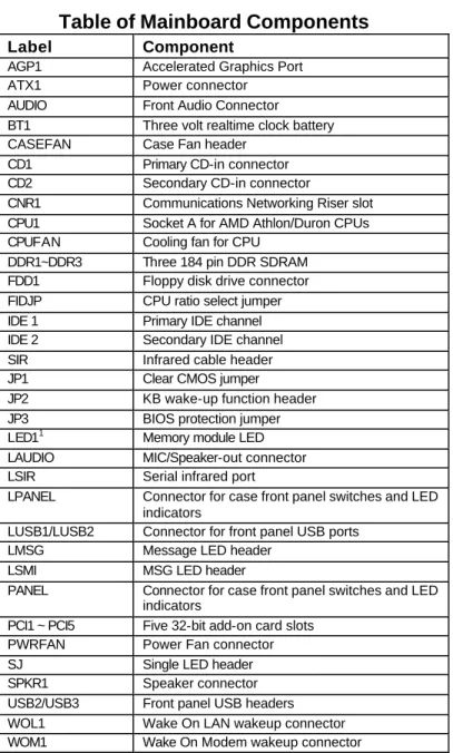
Table of Mainboard Components
Label Component
AGP1 Accelerated Graphics Port ATX1 Power connector AUDIO Front Audio Connector BT1 Three volt realtime clock battery CASEFAN Case Fan header
CD1 Primary CD-in connector CD2 Secondary CD-in connector
CNR1 Communications Networking Riser slot CPU1 Socket A for AMD Athlon/Duron CPUs CPUFAN Cooling fan for CPU
DDR1~DDR3 Three 184 pin DDR SDRAM FDD1 Floppy disk drive connector FIDJP CPU ratio select jumper IDE 1 Primary IDE channel IDE 2 Secondary IDE channel SIR Infrared cable header JP1 Clear CMOS jumper
JP2 KB wake-up function header JP3 BIOS protection jumper LED11 Memory module LED LAUDIO MIC/Speaker-out connector LSIR Serial infrared port
LPANEL Connector for case front panel switches and LED indicators
LUSB1/LUSB2 Connector for front panel USB ports LMSG Message LED header
LSMI MSG LED header
PANEL Connector for case front panel switches and LED indicators
PCI1 ~ PCI5 Five 32-bit add-on card slots PWRFAN Power Fan connector SJ Single LED header SPKR1 Speaker connector USB2/USB3 Front panel USB headers WOL1 Wake On LAN wakeup connector WOM1 Wake On Modem wakeup connector
1
The red indicator LED1 turns on if your system is still pow-ered, at which time memory modules cannot be installed or
C
C
h
h
o
o
o
o
s
s
i
i
n
n
g
g
a
a
C
C
o
o
m
m
p
p
u
u
t
t
e
e
r
r
C
C
a
a
s
s
e
e
There are many types of computer cases on the market. The mainboard complies with the specifications for the ATX sys-tem case. Some features on the mainboard are implemented by cabling connectors on the mainboard to indicators and switches on the system case. Ensure that your case supports all the features required. The mainboard can support one or two floppy diskette drives and four enhanced IDE drives. En-sure that your case has sufficient power and space for all the drives that you intend to install.
Most cases have a choice of I/O templates in the rear panel. Make sure that the I/O template in the case matches the I/O ports installed on the rear edge of the mainboard.
This mainboard has an ATX form factor of 220 x 304 mm. Choose a case that accommodates this form factor.
This concludes Chapter 1. Chapter 2 explains how to install the mainboard.
C
C
h
h
a
a
p
p
t
t
e
e
r
r
2
2
Installing the Mainboard
S
S
a
a
f
f
e
e
t
t
y
y
P
P
r
r
e
e
c
c
a
a
u
u
t
t
i
i
o
o
n
n
s
s
Follow these safety precautions when installing the mainboard:
• Wear a grounding strip attached to a grounded device to avoid damage from static electricity.
• Discharge static electricity by touching the metal case of a safely grounded object before working on the mainboard.
• Leave components in the static-proof bags they came in.
• Hold all circuit boards by the edges. Do not bend cir-cuit boards.
Q
Q
u
u
i
i
c
c
k
k
G
G
u
u
i
i
d
d
e
e
This Quick Guide suggests the steps you can take to build your system with the mainboards.
The following table describes installing specific components:
Locating Mainboard Components Go to page 4
Installing Jumpers Go to page 9
Installing the Mainboard in a Case Go to page 13
Installing Case Components Go to page 14
Installing the CPU Go to page 16
Installing Memory Go to page 19
Installing an HDD and CD-ROM Drive Go to page 21
Installing an FDD Go to page 24
Installing Add-on Cards Go to page 25
Connecting Options Go to page 27
Connecting Peripheral (I/O) Devices Go to page 32
Note: The appendix provides a quick reference for jumper settings.
C
C
h
h
e
e
c
c
k
k
i
i
n
n
g
g
J
J
u
u
m
m
p
p
e
e
r
r
S
S
e
e
t
t
t
t
i
i
n
n
g
g
s
s
This section explains how to set jumpers for correct configura-tion of the mainboard.
Setting Jumpers
Use the mainboard jumpers to set system configuration op-tions. Jumpers with more than one pin are numbered. When setting the jumpers, ensure that the jumper caps are placed on the correct pins.
Short Open
This illustration shows a 2-pin jumper. When the jumper cap is placed on both pins, the jumper is SHORT. If you remove the jumper cap, or place the jumper cap on just one pin, the jumper is OPEN.
1 2
3
This illustration shows a 3-pin jumper. Pins 1 and 2 are SHORT.
Checking Jumper Settings
Jumper Settings
Jumper Type Description Setting (default)
JP1 3 pin Clear CMOS 1-2: Normal
2-3: Clear
JP1
1
JP2 3 pin KB wake-up function 1-2: Enable 2-3: DisableJP2
1
JP3 2 pin BIOS protec-tion
Open: Disable
Short: Enable
JP3
1
FIDJP 10 pin CPU ratio selector
Refer to next
page
FIDJP
JP1 Clear CMOS Enables you to clear the BIOS:
1. Turn the system off.
2. Short pins 2 and 3 on jumper 1.
3. Return the jumper to the normal setting.
4. Turn the system on. The BIOS is returned to the default settings.
JP2 KB wake-up function
Enables you to wake-up the system by PS/2 keyboard. JP3 BIOS protection
Enables you to prevent the BIOS from being up dated (flashed). Open the jumper if you are going to update your BIOS. After updating the BIOS, short the jumper to protect the BIOS from being flashed. For instructions on updating the BIOS refer to Chapter 3.
FIDJP CPU ratio selector
Enables you to set the CPU ratio. Please make sure that your CPU ratio can be adjusted.
1-2 3-4 5-6 7-8 9-10 Ratio
Short By CPU
Open Open Open Open Open 10.5 Open Open Open Open Short 6.5 Open Open Open Short Open 8.5 Open Open Open Short Short 12.5 (higher) Open Open Short Open Open 9.5 Open Open Short Open Short 5.5 Open Open Short Short Open 7.5 Open Open Short Short Short 11.5 Open Short Open Open Open 10.0 Open Short Open Open Short 6.0 Open Short Open Short Open 8.0 Open Short Open Short Short 12.0 Open Short Short Open Open 9.0 Open Short Short Open Short 5.0 Open Short Short Short Open 7.0 Open Short Short Short Short 11.0
I
I
n
n
s
s
t
t
a
a
l
l
l
l
i
i
n
n
g
g
t
t
h
h
e
e
M
M
a
a
i
i
n
n
b
b
o
o
a
a
r
r
d
d
i
i
n
n
a
a
C
C
a
a
s
s
e
e
Refer to the following illustration and instructions for installing the mainboard in a case:
This illustration shows an example of a main-board being installed in a tower-type case:
Note: Do not over-tighten the screws as this can stress the mainboard.
Most system cases have mounting brackets in-stalled in the case, which correspond to the holes in the mainboard. Place the mainboard over the mounting brackets and secure the mainboard into the mounting brackets with screws.
2. Secure the screws in the mainboard holes that align with the chassis holes
1. Place the mainboard over the case fasteners
The mainboard has a set of I/O ports on the rear edge. En-sure that your case has an I/O template that supports the I/O ports and expansion slots.
C
C
o
o
n
n
n
n
e
e
c
c
t
t
i
i
n
n
g
g
C
C
a
a
s
s
e
e
C
C
o
o
m
m
p
p
o
o
n
n
e
e
n
n
t
t
s
s
After you have installed the mainboard into a case, you can begin connecting the mainboard components. Refer to the fol-lowing:
1. Connect the case power supply connector to ATX1. 2. Connect the CPU cooling fan cable to CPUFAN. 3. Connect the case cooling fan connector to either
PWRFAN or CASFAN.
The following page explains how to make panel (PANEL/LPANEL) connections.
The Panel and LPanel Connectors
The panel connectors provide a set of switch and LED con-nectors found on ATX or Micro ATX cases. Select one from the two types of panel connector supported by this mainboard.
PANEL
Device Pins Empty 10 N/C 9 Power ON/OFF 6, 8 Reset Switch 5, 7 Green LED Indicator 2, 4 HDD LED +1, -3 HDD LED (Pins 1, 3) 2 1 Reset Switch (Pins 5, 7) Power Switch (Pins 6, 8) Green LED (Pins 2, 4) Empty (Pin 10) 10 9 N/C (Pin 9)LPANEL
Device Pins Reset Switch 13, 14 Case Speaker 9 ~ 12 Power Switch 5, 6 Power LED +4 Green Power LED -3 Yellow Power LED -2 HDD LED +1, -8 HDD LED (Pins 1, 8) 8 1 Reset Switch (Pins 13, 14) Case Speaker (Pins 9 ~ 12)Yellow Power LED (Pin 2) Empty (Pin 7) 14 7 Power Switch (Pin 5, 6)
Green Power LED (Pin 3) Power LED (Pin 4)
Note: The plus sign (+) indicates a pin which must be con-nected to a positive voltage.
I
I
n
n
s
s
t
t
a
a
l
l
l
l
i
i
n
n
g
g
H
H
a
a
r
r
d
d
w
w
a
a
r
r
e
e
Installing the Processor
Caution: When installing a CPU heatsink and cooling fan make sure that you DO NOT scratch the mainboard or any of the surface-mount resistors with the clip of the cooling fan. If the clip of the cooling fan scrapes across the m ain-board, you may cause serious damage to both the mainboard and the processor.
On most mainboards, there are small surface-mount resis-tors near the processor socket, which may be damaged if the cooling fan is carelessly installed.
Avoid using cooling fans with sharp edges on the fan casing and the clips. Also, install the cooling fan in a well-lit work area so that you can clearly see the mainboard and proces-sor socket.
Before installing the Processor
This mainboard automatically determines the CPU clock fre-quency and system bus frefre-quency for processor. You may be able to change these automatic settings by changing the set-tings in the system Setup Utility. We strongly recommend that you do not overclock the mainboard to run processors or other components faster than their rated speed.
Warning: Overclocking components can adversely affect the reliability of the system and introduce errors into your system. Overclocking can permanently damage the main-board by generating excess heat in components that are run beyond the rated limits.
This mainboard has a Socket 462 processor socket. When choosing a processor, consider the performance requirements of the system. Performance is based on the processor design, the clock speed and system bus frequency of the processor, and the quantity of internal cache memory and external cache memory.
CPU Installation Procedure
The following illustration shows CPU installation components:
Follow these instructions to install the CPU:
1. Pull the CPU socket locking lever away from the socket to unhook it and raise the locking lever to the upright position.
2. Identify the pin A-1 corner on the CPU socket and the pin A-1 corner on the processor.
3. Match the pin A-1 corners and insert the processor into the socket. Do not use force.
4. Swing the locking lever down and hook it under the latch on the edge of the socket.
6. Lower the CPU fan/heatsink unit onto the CPU and CPU socket and then snap the fan/heatsink into place. 7. Plug the CPU fan power cable into the CPU cooling
Install Memory Modules
This mainboard accommodates 184-pin 2.5V unbuffered Double Data Rate (DDR) SDRAM memory modules. The memory chips must be standard or registered SDRAM (Syn-chronous Dynamic Random Access Memory).
This mainboard is capable of auto detecting the type of mem-ory modules (DDR SDRAM) you have installed and then automatically adjusting the voltage to the appropriate level.
Note: This mainboard only supports up to 2 unbuffere d DDR333 DIMM
The memory bus can run at 100 MHz or 133 MHz. If your processor operates over a 100 MHz system bus, you can in-stall PC200 or PC266 memory modules that operate over a 100 MHz or 133 MHz memory bus. If your processor operates over a 133 MHz system bus, you can only install PC266 or PC333 memory modules that operate over a 133 MHz or 166 MHz memory bus.
Note: SDRAM provides 800 MB/s or 1 GB/s data transfer depending on whether the bus is 100MHz or 133MHz. Double Data Rate SDRAM (DDR SDRAM) doubles the rate to 1.6 GB/s or 2.1 GB/s or 2.7 GB/s at memory bus 100 Mhz or 133 MHz or 166 MHz. DDR SDRAM uses additional power and ground lines and requires 184-pin DIMM mo dules rather than the 168-pin DIMMs used by SDRAM.
Installation Procedure
The mainboard accommodates three memory modules. You must install at least one module in any of the three slots. Each module can be installed with 32 MB to 512 MB of memory; to-tal memory capacity is 1.5 GB (PC200/PC266 DIMM) or 1.0 GB (PC333 DIMM).
1. Align the memory module with the slot. The DIMM slots are keyed with notches and the DIMMs are keyed with cutouts so that they can only be installed correctly. Check that the cutouts on the DIMM module edge connector match the notches in the DIMM slot:
Cutout Notch
Latch Latch
3. Install the DIMM module into the slot and press it firmly down so that it seats correctly. The slot latches are levered upwards and latch on to the edges of the DIMM when it is installed correctly.
Installing a Hard Disk Drive/CD-ROM
This section describes how to install IDE devices such as a hard disk drive and a CD-ROM drive.
About IDE Devices
Your mainboard has a primary and secondary IDE channel in-terface (IDE1 and IDE2). An IDE ribbon cable supporting two IDE devices is bundled with the mainboard. IDE devices have jumpers or switches that are used to set the IDE device as MASTER or SLAVE. Refer to the IDE device user’s manual. If you want to install more than two IDE devices, get a second IDE cable and you can add two more devices to the secon-dary IDE channel.
When installing two IDE devices on one cable, ensure that one device is set to MASTER and the other device is set to SLAVE. The documentation of your IDE device explains how to do this.
About UDMA
This mainboard supports UltraDMA 66/100. UDMA is a tech-nology that accelerates the performance of devices in the IDE channel. Install IDE devices that support UDMA and use IDE cables that support UDMA for better performance.
Installing a Hard Disk Drive
1. Install the hard disk drive into the drive cage in your system case.
2. Plug the IDE cable into IDE1 (A).
Note: Ribbon cable connectors are usually keyed so that they can only be installed correctly on the device connector. If the connector is not keyed, make sure that you match the pin -1 side of the cable connector with the pin-1 side of the device connector. Each connector has the pin -1 side clearly marked. The pin-1 side of each ribbon cable is always marked with a colored stripe on the cable.
3. Plug an IDE cable connector into the hard disk drive IDE connector. It doesn't matter which connector on the cable you use. Ensure that the pin-1 side of the cable is matched with the pin-1 side of the connector. Refer to the previous note (B).
4. Plug a power cable from the case power supply into the power connector on the hard disk drive (C).
When you first start up your system, the BIOS should auto-matically detect your hard disk drive. If it doesn’t, enter the Setup Utility and use the IDE Hard Disk Auto Detect feature to configure the hard disk drive that you have installed. See Chapter 3 for more information.
Installing a CD-ROM/DVD Drive
1. Install the CD-ROM/DVD drive into the drive cage in your system case (A).
2. Plug the IDE cable into IDE1. If you have already in-stalled an HDD, you can use the free connector on its IDE cable (B).
Note: Ribbon cable connectors are usually keyed so that they can only be installed correctly on the device connector. If the connector is not keyed, make sure that you match the pin-1 side of the cable connector with the pin-1 side of the device connector. Each connector has the pin -1 side clearly marked. The pin-1 side of each ribbon cable is always marked with a colored stripe on the cable.
3. Plug an IDE cable connector into the CD-ROM/DVD drive IDE connector. It doesn't matter which connector on the cable you use. Ensure that the pin-1 side of the cable is matched with the pin-1 side of the connector. Refer to the previous note.
4. Use the audio cable provided with the CD-ROM/DVD drive to connect to the mainboard CD-in connector CD1 or CD2 (D).
5. Plug a power cable from the case power supply into the power connector on the CD-ROM/DVD drive (C). When you first start up your system, the BIOS should auto-matically detect your CD-ROM/DVD drive. If it doesn’t, enter the Setup Utility and configure the CD-ROM/DVD drive that you have installed. See Chapter 3 for more information.
Installing a Floppy Diskette Drive
The mainboard has a floppy diskette drive (FDD) interface ships with a diskette drive ribbon cable that supports one or two floppy diskette drives. You can install a 5.25-inch drive and a 3.5-inch drive with various capacities. The floppy disk-ette drive cable has one type of connector for a 5.25-inch drive and another type of connector for a 3.5-inch drive
1. Install the FDD into the drive cage in your system case. 2. Plug the FDD cable into FDD1 (A).
Note: Ribbon cable connectors are usually keyed so that they can only be installed correctly on the device connector. If the connector is not keyed, make sure that you match the pin -1 side of the cable connector with the pin-1 side of the device connector. Each connector has the pin -1 side clearly marked. The
pin-1 side of each ribbon cable is always marked with a colored stripe on the cable.
3. Plug one of the connectors on the FDD cable into the FDD connector (B). It doesn't matter which connector on the cable you use. Ensure that the pin-1 side of the cable is matched with the pin-1 side of the connector. Refer to the previous note.
4. Plug a power cable from the case power supply into the power connector on the FDD (C).
When you first start up your system, go immediately to the Setup Utility and use the Standard page to configure the floppy diskette drives that you have installed. See Chapter 3 for more information.
Installing Add-on Cards
This mainboard has five 32-bit PCI (Peripheral Components Interconnect) expansion slots, one 4xAGP slot, and one Communications and Networking Riser (CNR) slot.
PCI Slots PCI slots are used to install expansion cards that have the 32-bit PCI interface. 4xAGP Slot The 4xAGP slot is used to install a
graph-ics adapter that supports the 4xAGP specification and has a 4xAGP edge con-nector.
CNR Slot This slot is used to insert CNR cards with Modem and Audio functionality.
Note: Before installing an add-on card, check the docu-mentation for the card carefully. If the card is not Plug and Play, you may have to manually configure the card before installation.
1. Remove a blanking plate from the system case corre-sponding to the slot you are going to use.
2. Install the edge connector of the add-on card into the expansion slot. Ensure that the edge connector is cor-rectly seated in the slot.
3. Secure the metal bracket of the card to the system case with a screw.
Note: For some add-on cards, for example graphics adapters and network adapters, you have to install drivers and software before you can begin using the add-on card.
Connecting Optional Devices
Refer to the following for information on connecting the main-board’s optional devices:
AUDIO: Front Audio Connector
This connector is used to attach to Audio equipment embed-ded into or attached to the case.
Pin Signal Name Pin Signal Name 1 3 5 7 9 AUD_MIC MIC_BIAS AUD_F_R RESERVED AUD_F_L 2 4 6 8 10 AUD_GND AUD_VCC AUD_RET_R EMPTY AUD_RET_L
LAUDIO: Mic/Speaker Out header
Pin Signal Name Pin Signal Name
1 3 5 7 9 11 13 15
Active LINE Out (R) GND (aLO)
GND (+12) +12V (1A) MIC
Front LINE Out(R) Front LINE Out (L) GND (tLO) 2 4 6 8 10 12 14 16
Active LINE Out (L) GND (aLO) GND (+12) EMPTY GND (MIC) LINE Next (R) LINE Next (L) EMPTY
LUSB 1/2: USB panel connector
This USB panel connector (which is specially designed for OEM customers) connects to the front panel or case USB ports that comply with the OEM specifications.
LUSB1 Pin Assignment
Pin Signal Name Pin Signal Name
1 3 5 7 9 +5V USB2– USB2+ Ground Ground 2 4 6 8 10 Ground Empty USB3+ USB3– +5V
LUSB2 Pin Assignment
Pin Signal Name Pin Signal Name
1 3 5 7 9 +5V USB4– USB4+ Ground Ground 2 4 6 8 10 Ground Empty USB5+ USB5– +5V
USB 2/3: USB panel connector
The mainboard has USB ports installed on the rear edge I/O port array. However, some computer cases have a special module that mounts USB ports at the front of the case. If you have this kind of case, use auxiliary USB connector USB1 to connect the front-mounted ports to the mainboard.
USB2 Pin Assignment
Pin Signal Name Pin Signal Name
1 3 5 7 9 VCC USBP2– USBP2+ Ground Empty 2 4 6 8 10 VCC USBP3– USBP3+ Ground OC#
USB3 Pin Assignment
Pin Signal Name Pin Signal Name
1 3 5 7 9 VCC USBP4– USBP4+ Ground Empty 2 4 6 8 10 VCC USBP5– USBP5+ Ground OC#
WOL1/WOM1: Wake On LAN/Wake On Modem
If you have installed a LAN card, use the cable provided with the card to plug into the mainboard WOL1 connector. This en-ables the Wake On LAN (WOL) feature. When your system is in a power-saving mode, any LAN signal automatically re-sumes the system. You must enable this item using the Power Management page of the Setup Utility.Pin Signal Name 1 2 3 5VSB Ground SENSE
If you have installed a modem, use the cable provided with the modem to plug into the mainboard WOM1 connector. This enables the Wake On Modem (WOM) feature. When your sys-tem is in a power-saving mode, any modem signal automatically resumes the system. You must enable this item using the Power Management page of the Setup Utility. See Chapter 3 for more information.
SIR: Infrared port
The mainboard supports an Infrared (IR) data port. Infrared ports allow the wireless exchange of information between your computer and similarly equipped devices such as printers, laptops, Personal Digital Assistants (PDAs), and other com-puters.
Pin Signal Name Pin Signal Name
1 3 5 N/A +5V IRTX/CIRTX 2 4 6 Empty GND IRRX/CIRRX
LSIR: Serial infrared port
The mainboard supports a Serial Infrared (SIR) data port. In-frared ports allow the wireless exchange of information between your computer and similarly equipped devices such as printers, laptops, Personal Digital Assistants (PDAs), and other computers.
Pin Signal Name
1 2 3 4 5 VCC Empty IRRX GND IRTX
SPKR1: Internal speaker
Connect the internal speaker connector to this header.
Pin Signal Name
1 2 3 4 SPKR NC Ground +5V
SJ: Single color LED
This connector is used to attach to devices that need a single color LED indicator.
LSMI: System Management Interrupt
This connector is for use with SMI hardware interrupt power management.
Pin Signal Name
1 2
ExtSMI Ground
LMSG: Message LED header
This connector is used to attach to devices that need a dual color LED indicator.
C
C
o
o
n
n
n
n
e
e
c
c
t
t
i
i
n
n
g
g
I
I
/
/
O
O
D
D
e
e
v
v
i
i
c
c
e
e
s
s
The backplane of the mainboard has a full set of I/O ports:
PS/2 mouse PS/2 keyboard USB ports Parallel port (LPT1) Serial port COM 1 Serial port COM 2 Line-in Game port Microphone Line-out
1. Use the upper PS/2 port to connect a PS/2 pointing device. Use the lower PS/2 port to connect a PS/2 keyboard.
2. Use the USB ports to connect USB devices.
3. Use LPT1 to connect printers or other parallel commu-nications devices.
4. Use the COM ports to connect serial devices such as mice or fax/modems. COM1 is identified by the system as COM1/3. COM2 is identified by the system as COM2/4.
5. Use the game port to connect a joystick or a MIDI de-vice.
6. Use the three audio ports to connect audio devices. The left side jack is for a stereo line-out signal. The middle jack is for a stereo line-in signal. The right side jack is for a microphone.
External Connector Color Coding
Many connectors now use standard colors as shown in the table below.
Connector Color
Analog VGA Blue
Audio line-in Light blue
Audio line-out Lime
Digital monitor / flat panel White
IEEE 1394 Grey
Microphone Pink
MIDI/Game Gold
Parallel Burgundy
PS/2 compatible keyboard Purple
PS/2 compatible mouse Green
Serial Teal or Turquoise
Speaker out/subwoofer Orange Right-to-left speaker Brown
USB Black
Video out Yellow
SCSI, network, telephone, modem
None
C
C
h
h
a
a
p
p
t
t
e
e
r
r
3
3
Using BIOS
A
A
b
b
o
o
u
u
t
t
t
t
h
h
e
e
S
S
e
e
t
t
u
u
p
p
U
U
t
t
i
i
l
l
i
i
t
t
y
y
The computer uses the latest Award BIOS with support for Windows Plug and Play. The CMOS chip on the mainboard contains the ROM setup instructions for configuring the main-board BIOS.
The BIOS (Basic Input and Output System) Setup Utility dis-plays the system's configuration status and provides you with options to set system parameters. The parameters are stored in battery-backed-up CMOS RAM that saves this information even when the power is turned off. When the system is turned back on, the system is configured with the values found in CMOS.
The BIOS Setup Utility enables you to configure:
• Hard drives, diskette drives, and peripherals
• Video display type and display options
• Password protection from unauthorized use
• Power management features
The settings made in the Setup Utility affect how the computer performs. Before using the Setup Utility, ensure that you un-derstand the Setup Utility options. Only change settings appropriate for the way you use the computer.
The Standard Configuration
A standard configuration has already been set in the Setup Utility. However, we recommend that you read this chapter in case you need to make any changes in the future.
This Setup Utility should be used:
• when changing the system configuration
• when a configuration error is detected and you are prompted to make changes to the Setup Utility
• when trying to resolve IRQ conflicts
• when making changes to the Power Management con-figuration
• when changing the password or making other changes to the Security Setup
Entering the Setup Utility
When you power on the system, BIOS enters the Power-On Self Test (POST) routines. POST is a series of built-in diag-nostics performed by the BIOS. After the POST routines are completed, the following message appears:
Press DEL to enter SETUP
Pressing the delete key accesses the BIOS Setup Utility:
CMOS Setup Utility – Copyright (C) 1984 – 2001 Award Software Standard CMOS Features
Advanced BIOS Features Advanced Chipset Features Integrated Peripherals Power Management Setup PnP/PCI Configurations PC Health Status
Frequency/Voltage Control Load Fail-Safe Defaults Load Optimized Defaults Set Password
Save & Exit Setup Exit Without Saving Esc : Quit ↑ ↓ → ← : Select Item F10 : Save & Exit Setup
Time, Date, Hard Disk Type . . .
BIOS Navigation Keys
The BIOS navigation keys are listed below:
Key Function
Esc Exits the current menu
←↑↓→ Scrolls through the items on a menu +/–
/PU/PD
Modifies the selected field's values
F10 Saves the current configuration and exits setup F1 Displays a screen that describes all key
func-tions
F5 Loads previously saved values to CMOS F6 Loads a minimum configuration for
trouble-shooting.
F7 Loads an optimum set of values for peak per-formance
Updating the BIOS
You can download and install updated BIOS for this main-board from the manufacturer's web site. New BIOS provides support for new peripherals, improvements in performance, or fixes for known bugs. Install new BIOS as follows:
1. If your mainboard has a BIOS protection jumper, change the setting to allow BIOS flashing. Refer to Appendix A for jumper settings.
2. If your mainboard has an item called Firmware Write Protect in Advanced BIOS features, disable it. Firm-ware Write Protect prevents BIOS from being overwritten.
3. Create a bootable system disk. Refer to Windows online help for information on creating a bootable sys-tem disk.
4. Download the Flash Utility and new BIOS file from the manufacturer's Web site. Copy these files to the sys-tem diskette you created in Step 3.
5. Turn off your computer and insert the system diskette in your computer's diskette drive. You might need to run the Setup Utility and change the boot priority items on the Advanced BIOS Features Setup page, to force your computer to boot from the floppy diskette drive first. 6. At the A:\ prompt, type the Flash Utility program name
and press <Enter>. You see a screen similar to the fol-lowing:
FLASH MEMORY WRITER V7.33
(C) Award Software 1999 All Rights Reserved For (MAINBOARD NAME) DATE: 10/26/2000 Flash Type
File Name to Program :____________________
Error Message
7. Type the filename of the new BIOS in the “File Name to Program” text box. Follow the onscreen directions to update the mainboard BIOS.
8. When the installation is complete, remove the floppy diskette from the diskette drive and restart your com-puter. If your mainboard has a Flash BIOS jumper, reset the jumper to protect the newly installed BIOS from being overwritten.
U
U
s
s
i
i
n
n
g
g
B
B
I
I
O
O
S
S
When you start the Setup Utility, the main menu appears. The main menu of the Setup Utility displays a list of the options that are available. A highlight indicates which option is cur-rently selected. Use the cursor arrow keys to move the highlight to other options. When an option is highlighted, exe-cute the option by pressing <Enter>.
Some options lead to pop-up dialog boxes that prompt you to verify that you wish to execute that option. Other options lead to dialog boxes prompt you for information.
Some options (marked with a triangle ) lead to submenus that enable you to change the values for the option. Use the cursor arrow keys to scroll through the items in the submenu. In this manual, default values are enclosed in parenthesis. Submenu items are denoted by a triangle .
Standard CMOS Features
This option displays a table of items defining basic information about your system.
CMOS Setup Utility – Copyright (C) 1984 – 2001 Award Software Standard CMOS Features
Item Help Date (mm:dd:yy) Tue, July 11 2000
Time (hh:mm:ss) 12 : 8 : 59 IDE Primary Master
IDE Primary Slave IDE Secondary Master IDE Secondary Slave
Drive A [1.44M, 3.5 in.] Drive B [None] Floppy 3 Mode Support [Disabled] Video [EGA/VGA] Halt On [All Errors]
Base Memory 640K Extended Memory 31744K Total Memory 32768K
Menu Level Change the day, month, year and century.
↑↓→ ← : Move Enter : Select +/-/PU/PD:Value: F10: Save ESC: Exit F1:General Help
Date and Time
The Date and Time items show the current date and time on the computer. If you are running a Windows OS, these items are automatically updated whenever you make changes to the Windows Date and Time Properties utility.
IDE Devices (None)
Your computer has two IDE channels (Primary and Secondary) and each channel can be installed with one or two devices (Master and Slave). Use these items to configure each device on the IDE channel.
Press <Enter> to display the IDE submenu:
CMOS Setup Utility – Copyright © 1984 – 2000 Award Software IDE Primary Master
Item Help IDE HDD Auto-Detection [Press Enter]
IDE Primary Master [Auto] Access Mode [Auto]
Capacity 0 MB Cylinder 0 Head 0 Precomp 0 Landing Zone 0 Sector 0 Menu Level To auto-detect the HDD’s size, head . . . on this channel
↑↓→ ← : Move Enter : Select +/-/PU/PD:Value: F10: Save ESC: Exit F1:General Help
F5:Previous Values F6:Fail-Safe Defaults F7:Optimized Defaults
IDE HDD Auto-Detection
Press <Enter> while this item is highlighted to prompt the Setup Utility to automatically detect and configure an IDE de-vice on the IDE channel.
Note: If you are setting up a new hard disk drive that sup-ports LBA mode, more than one line will appear in the parameter box. Choose the line that lists LBA for an LBA drive.
IDE Primary Master/Slave & Secondary Master/Slave (Auto)
Leave this item at Auto to enable the system to automatically de-tect and configure IDE devices on the channel. If it fails to find a device, change the value to Manual and then manually configure the drive by entering the characteristics of the drive in the items
Refer to your drive's documentation or look on the drive casing if you need to obtain this information. If no device is installed, change the value to None.
Note: Before attempting to configure a hard disk drive, ensure that you have the configuration information supplied by the manufacturer of your hard drive. In-correct settings can result in your system not recognizing the installed hard disk.
Access Mode
This item defines ways that can be used to access IDE hard disks such as LBA (Large Block Addressing). Leave this value at Auto and the system will automatically decide the fastest way to access the hard disk drive.
Press <Esc> to return to the Standard CMOS Features page.
Drive A/Drive B (1.44M, 3.5 in./None)
These items define the characteristics of any diskette drive at-tached to the system. You can connect one or two diskette drives.
Floppy 3 Mode Support (Disabled)
Floppy 3 mode refers to a 3.5-inch diskette with a capacity of 1.2 MB. Floppy 3 mode is sometimes used in Japan.
Video (EGA/VGA)
This item defines the video mode of the system. This main-board has a built-in VGA graphics system; you must leave this item at the default value.
Halt On (All Errors)
This item defines the operation of the system POST (Power On Self Test) routine. You can use this item to select which types of errors in the POST are sufficient to halt the system.
Base Memory, Extended Memory, and Total Memory
These items are automatically detected by the system at start up time. These are display-only fields. You cannot make changes to these fields.
Advanced BIOS Setup Option
This option displays a table of items that define advanced in-formation about your system.
CMOS Setup Utility – Copyright (C) 1984 – 2001 Award Software Advanced BIOS Features
Item Help Anti-Virus Protection [Disabled]
CPU Internal Cache [Enabled] External Cache [Enabled] Quick Power On Self Test [Enabled] First Boot Device [Floppy] Second Boot Device [HDD-0] Third Boot Device [LS120] Boot Other Device [Enabled] Swap Floppy Drive [Disabled] Boot Up Floppy Seek [Enabled] Boot Up NumLock Status [On] Gate A20 Option [Fast] Typematic Rate Setting [Disabled]
x Typematic Rate (Chars/Sec) 6 x Typematic Delay (Msec) 250
Security Option [Setup] APIC Mode [Enabled] OS Select For DRAM > 64MB [Non-OS2]
Menu Level Allows you to choose the VIRUS warning feature for IDE Hard Disk boot sector protection. If this function is enabled and someone attempts to write data into this area, BIOS will show a warning message on screen and alarm beep
↑↓→ ← : Move Enter : Select +/-/PU/PD:Value: F10: Save ESC: Exit F1:General Help
F5:Previous Values F6:Fail-Safe Defaults F7:Optimized Defaults
Anti-Virus Protection (Disabled)
When enabled, this item provides protection against viruses that try to write to the boot sector and partition table of your hard disk drive. You need to disable this item when installing an operating system. We recommend that you enable anti-virus protection as soon as you have installed an operating system.
CPU Internal Cache (Enabled)
All processors that can be installed in this mainboard use in-ternal level 1 (L1) cache memory to improve performance. Leave this item at the default value for better performance.
External Cache (Enabled)
Most processors that can be installed in this system use ex-ternal level 2 (L2) cache memory to improve performance. Leave this item at the default value for better performance.
Quick Power On Self Test (Enabled)
Enable this item to shorten the power on testing (POST) and have your system start up faster. You might like to enable this item after you are confident that your system hardware is op-erating smoothly.
1st/2nd/3rd Boot Device (Floppy/HDD-0/LS120)
Use these three items to select the priority and order of the devices that your system searches for an operating system at start-up time.
Boot Other Device (Enabled)
When enabled, the system searches all other possible loca-tions for an operating system if it fails to find one in the devices specified under the first, second, and third boot de-vices.
Swap Floppy Drive (Disabled)
If you have two floppy diskette drives in your system, this item allows you to swap the assigned drive letters so that drive A becomes drive B, and drive B becomes drive A.
Boot Up Floppy Seek (Enabled)
If this item is enabled, it checks the size of the floppy disk drives at start-up time. You don't need to enable this item un-less you have a legacy diskette drive with 360K capacity.
Boot Up NumLock Status (On)
This item defines if the keyboard Num Lock key is active when your system is started.
Gate A20 Option (Fast)
This item defines how the system handles legacy software that was written for an earlier generation of processors. Leave this item at the default value.
Typematic Rate Setting (Disabled)
If this item is enabled, you can use the following two items to set the typematic rate and the typematic delay settings for your keyboard.
• Typematic Rate (Chars/Sec): Use this item to define how many characters per second are generated by a held-down key.
• Typematic Delay (Msec): Use this item to define how many milliseconds must elapse before a held-down key begins generating repeat characters.
Security Option (Setup)
If you have installed password protection, this item defines if the password is required at system start up, or if it is only re-quired when a user tries to enter the Setup Utility.
APIC Mode (Enabled)
This item allows you to enable APIC (Advanced Programma-ble Interrupt Controller) functionality. APIC is an Intel chip that provides symmetric multiprocessing (SMP) for its Pentium systems.
OS Select For DRAM > 64 MB (Non-OS2)
This item is only required if you have installed more than 64 MB of memory and you are running the OS/2 operating sys-tem. Otherwise, leave this item at the default.
HDD S.M.A.R.T Capability (Disabled)
The S.M.A.R.T. (Self-Monitoring, Analysis, and Reporting Technology) system is a diagnostics technology that monitors and predicts device performance. S.M.A.R.T. software resides on both the disk drive and the host computer.
The disk drive software monitors the internal performance of the motors, media, heads, and electronics of the drive. The host software monitors the overall reliability status of the drive. If a device failure is predicted, the host software, through the Client WORKS S.M.A.R.T applet, warns the user of the im-pending condition and advises appropriate action to protect the data.
Report No FDD For WIN95 (Yes)
Windows 95, select Yes for this item to ensure compatibility with the Windows 95 logo certification. Otherwise, select No.
Video BIOS Shadow (Enabled)
When set to Enabled, the system copies the VGA BIOS into system DRAM.
Small Logo (EPA) Show (Disabled)
Advanced Chipset Features Option
This option displays a table of items that define critical timing parameters of the mainboard. You should leave the items on this page at their default values unless you are very familiar with the technical specifications of your system hardware. If you change the values incorrectly, you may introduce fatal er-rors or recurring instability into your system.
CMOS Setup Utility – Copyright (C) 1984 – 2001 Award Software Advanced Chipset Features
Item Help Advanced DRAM Control 1 [Press Enter]
Advanced DRAM Control 2 [Press Enter] Memory Hole at 15M-16M [Disabled] AGP Fast Write control [Enabled] AGP Data Transfer Rates [Support 4X] AGP Aperture Size [64MB] PCI SLOT 5 Support [Enabled]
Menu Level
↑ ↓→ ← : Move Enter : Select +/-/PU/PD:Value: F10: Save ESC: Exit F1:General Help
Advanced DRAM Control 1
Scroll to this item and press <Enter> to view the following screen:
CMOS Setup Utility – Copyright (C) 1984 – 2001 Award Software Advanced DRAM Control 1
Item Help Auto configuration [Normal Mode]
CPU/DRAM CLK Synch CTL [Auto] DRAM BackGround Cycles [Auto] LD-Off Dram RD/WR Cycles [Auto]
Menu Level
↑ ↓→ ← : Move Enter : Select +/-/PU/PD:Value: F10: Save ESC: Exit F1:General Help
F5:Previous Values F6:Fail-Safe Defaults F7:Optimized Defaults
Auto Configuration (Normal Mode)
This is the DRAM auto configuration option, which can be set to Safe Mode, Normal Mode, Fast Mode or Ultra Mode.
CPU/DRAM CLK Synch CTL (Auto)
This option allows you set the CPU/DRAM synchronization. The valid options are AUTO, Synchronous, and Asynchronous.
DRAM BackGround Cycles (Auto)
This option allows you to set the DRAM background cycles. The valid options are AUTO, Delay 1T, and Normal.
LD-Off Dram RD/WR cycles (Auto)
This option allows you to set the LD-Off DRAM RD/WR cycles. Valid values are AUTO, Delay 1T, and Normal.
Advanced DRAM control 2
Scroll to this item and press <Enter> to view the following screen:
CMOS Setup Utility – Copyright (C) 1984 – 2001 Award Software Advanced DRAM Control 2
Item Help CS[5:0]# Hold Time CTL [+0.5 ns]
DQS/CSB Hold Time CTL [+0.5 ns]
CKE Hold Time CTL [+0.5 ns] Menu Level
↑ ↓→ ← : Move Enter : Select +/-/PU/PD:Value: F10: Save ESC: Exit F1:General Help
F5:Previous Values F6:Fail-Safe Defaults F7:Optimized Defaults
CS[5:0]# Hold Time CTL (+0.5 ns)
This option allows you to set the CS Hold Time. Valid values are +.05 ns, +.1.0 ns, +1.5 ns, and +2.0 ns.
DQS/CSB Hold Time CTL (+0.5 ns)
This option allows you to set the DQS/CSB Hold Time. Valid values are +.05 ns, +.1.0 ns, +1.5 ns, and +2.0 ns.
CKE Hold Time CTL (+0.5 ns)
This option allows you to set the CKE Hold Time. Valid values are +.05 ns, +.1.0 ns, +1.5 ns, and +2.0 ns.
Memory Hole at 15M-16M (Disabled)
This item is used to reserve memory space for ISA expansion cards that require it.
AGP Fast Write Control (Enabled)
This item allows you to enable or disable the caching of dis-play data for the video memory of the processor. Enabling can greatly improve the display speed. If your graphics display card does not support this feature, you need to disable this item.
AGP Data Transfer Rates (Support 4X)
Determines the data transfer rate of AGP data at either 4X or 2X depending on your Advanced Graphics Card.
AGP Aperture Size (64MB)
This item defines the size of the aperture if you use an AGP graphics adapter. It refers to a section of the PCI memory ad-dress range used for graphics memory. We recommend that you leave this item at the default value.
PCI SLOT 5 Support (Enabled)
Enables PCI support for this mainboard.
Integrated Peripherals Option
This option displays a list of items that defines the operation of peripheral components on the system's input/output ports.
CMOS Setup Utility – Copyright (C) 1984 – 2001 Award Software Integrated Peripherals
Item Help SIS OnChip IDE Device [Press Enter]
SIS OnChip PCI Device [Press Enter] Onboard SuperI/O Device [Press Enter]
USB Controller [Enabled] USB keyboard Support [Disabled] IDE HDD Block Mode [Enabled] Init Display First [PCI Slot] AGP Auto Calibration [Enabled]
Menu Level
↑ ↓→ ← : Move Enter : Select +/-/PU/PD:Value: F10: Save ESC: Exit F1:General Help
SIS OnChip IDE Device
Scroll to this item and press <Enter> to view the following screen:
CMOS Setup Utility – Copyright (C) 1984 – 2001 Award Software SIS OnChip IDE Device
Item Help Internal PCI/IDE [Both]
Primary Master PIO [Auto] Primary Slave PIO [Auto] Secondary Master PIO [Auto] Secondary Slave PIO [Auto] Primary Master UltraDMA [Auto] Primary Slave UltraDMA [Auto] Secondary Master UltraDMA [Auto] Secondary Slave UltraDMA [Auto] IDE Burst Mode [Enabled]
Menu Level
↑ ↓→ ← : Move Enter : Select +/-/PU/PD:Value: F10: Save ESC: Exit F1:General Help
F5:Previous Values F6:Fail-Safe Defaults F7:Optimized Defaults
Internal PCI/IDE (Both)
Use these items to enable or disable the internal PCI IDE channels that are integrated on the mainboard.
IDE Primary/Secondary Master/Slave PIO (Auto)
Each IDE channel supports a master device and a slave de-vice. These four items let you assign which kind of PIO (Programmed Input/Output) is used by IDE devices. Choose Auto to let the system auto detect which PIO mode is best, or select a PIO mode from 0-4.
IDE Primary/Secondary Master/Slave UltraDMA (Auto)
Each IDE channel supports a master device and a slave de-vice. This mainboard supports UltraDMA technology, which provides faster access to IDE devices.
If you install a device that supports UltraDMA, change the ap-propriate item on this list to Auto. You may have to install the UltraDMA driver supplied with this mainboard in order to use an UltraDMA device.
IDE Burst Mode (Enabled)