NoiseTutor
NoiseTutor System Manual
Copyright
Copyright 2015 by PCB Piezotronics, Inc. This manual is copyrighted, with all rights reserved. The manual may not be copied in whole or in part for any use without prior written consent of PCB Piezotronics, Inc.
PCB® is a registered trademark of PCB Group, Inc. Windows® operating systems are registered trademarks of Microsoft Corporation. Sierra Wireless® and the Sierra Wireless logo are registered trademarks of Sierra Wireless.
Disclaimer
The following paragraph does not apply in any state or country where such statements are not agreeable with local law:
Even though PCB Piezotronics, Inc. has reviewed its documentation, PCB Piezotronics, Inc. makes no warranty or representation, either expressed or implied, with respect to this instrument and documentation, its quality, performance, merchantability, or fitness for a particular purpose. This documentation is subject to change without notice, and should not be construed as a commitment or representation by PCB Piezotronics, Inc.
This publication may contain inaccuracies or typographical errors. PCB Piezotronics, Inc. will periodically update the material for inclusion in new editions. Changes and improvements to the information described in this manual may be made at any time.
Record of Purchase Date and Serial Number
Model 831 SLM: ________ Serial Number: ___________
Preamplifier Model: _________ Serial Number: ___________
Microphone Model: _________ Serial Number: ___________ Recycling
PCB Piezotronics, Inc. is an environmentally friendly organization and encourages our customers to be environmentally conscious. When this product reaches its end of life, please recycle the product through a local recycling center or return the product to:
PCB Piezotronics, Inc. Attn: Recycling Coordinator 1681 West 820 North
Provo, Utah, USA 84601-1341
where it will be accepted for disposal.
Warranty
For warranty information, refer to our Terms and Conditions of Sale on our website, www.larsondavis.com/TermsConditions.aspx.
Table of Contents
Chapter 1 Introduction
1-1
Checking NoiseTutor Components ... 1-2
Optional Accessories ... 1-3
Configuring the NoiseTutor Server ... 1-4
System requirements for NoiseTutor Server Configuration ... 1-5
Setting up the NoiseTutor Station ... 1-6
Installing NoiseTutor Station Software ... 1-6
System Requirements for NoiseTutor Station Software ... 1-6
Chapter 2 Server Installation and Setup
2-1
Installing IIS on Windows 7 Operating System ... 2-1
Adding Audio MIME Types ... 2-11
Installing the NoiseTutor Server Configuration Tool ... 2-14
Running the NoiseTutor Configuration Tool ... 2-16
Creating User Accounts for FTP Uploads ... 2-19
Setting up FTP Servers ... 2-30
Configuring Windows Firewalls ... 2-33
Verifying Access to FTP Servers ... 2-40
Local Access ... 2-40
Local Network Access ... 2-41
Public Access ... 2-42
Verifying Browser Connections ... 2-43
Chapter 3 Station Installation and Setup
3-1
Installing NoiseTutor Software ... 3-1
Starting the NoiseTutor Station ... 3-3
Installing NoiseTutor Station Licenses ... 3-4
Checking Battery Status ... 3-6
Checking the Station PC Power Settings ... 3-6
Restoring Settings for Automatic Wakeup ... 3-10
Checking the NoiseTutor Model 831 Run Preferences ... 3-12
Monitoring the Wireless Modem Connection ... 3-14
Specifying Main Application Settings ...3-14
Configuring Data Transmission and Delivery Settings ...3-17
Set Up SMTP (E-mail) Service ... 3-18
Set Up SMS (Text Messaging) Service ... 3-19
Add E-mail and SMS Recipient Lists ... 3-21
Specify Data Settings for E-mail Messages ... 3-22
Set up Data Delivery for FTP Server Sites ... 3-25
Create and Publish Graphical Reports to Websites ... 3-27
Updating Webpages from the NoiseTutor Station ...3-29
Connecting with WiFi ...3-31
Chapter 4 Wireless Gateway Setup for SMS Messaging
4-1
Configuring the LS300 for SMS Messaging ...4-1
Configuring the NoiseTutor Station for SMS Messaging ...4-3
Chapter 5 Station Software Reference
5-1
Setup Commands ...5-2
Working Mode ...5-3
Main Setup ...5-4
Recipient Lists ...5-6
Messaging ...5-8
SMTP (E-mail) ... 5-9
SMS (Text Messaging) ... 5-10
Graph ...5-11
Time History Setup ... 5-11
Spectrogram Setup ... 5-13
Live Graph Setup ... 5-14
Audio Recording ...5-15
Audio Snapshot ... 5-17
Event Detection ...5-19
Send E-mail ... 5-21
Send SMS (text messages) ... 5-22
Upload Graphs to Websites ... 5-23
Data File Settings ...5-24
FTP Setup Service ... 5-26
Realtime Report Settings ... 5-27
E-Mail Report ... 5-28
Daily, Weekly, or Monthly Monitoring ... 5-29
Web Publishing ... 5-30
Web Report Advanced Settings ... 5-33
System Administration Messages ... 5-34
E-mail System Administration Messages ... 5-34
SMS System Administration Messages ... 5-36
Main commands ... 5-37
Appendix A Technical Specifications
A-1
System Power Requirements ... A-1
Physical ... A-1
Environmental ... A-1
Station PC (provided) ... A-2
Items not Included ... A-2
C H A P T E R
1
Introduction
This manual describes how to set up and configure the Larson Davis NoiseTutor System. The NoiseTutor System is designed to provide portable and remote observation of monitoring sites with features for performing the following functions:
These functions can be used simultaneously, if desired.
• Provide customizable graphs of measurement data files, including time histories and spectrograms
• Provide customizable real-time graphical reports of sound measurements
• Deliver sound level data files and graphical reports via e-mail
• Deliver sound level data files and graphical reports to FTP servers
• Provide event detection and graphical event notification through e-mail, text messaging to cell phones, and web publishing
• Record audio files of measurements to be sent with reports
• Provide simplified and centralized method for specifying recipients for e-mail and text messaging
• Provide administrative e-mail and text messaging support for operating and maintaining the NoiseTutor System
The NoiseTutor System software comes pre-installed when NoiseTutor is purchased as a system.
Setting up the NoiseTutor System includes the following procedures:
1. Checking NoiseTutor Components 2. Configuring the NoiseTutor server 3. Setting up the NoiseTutor Station
4. Installing the NoiseTutor System software, if not already pre-installed
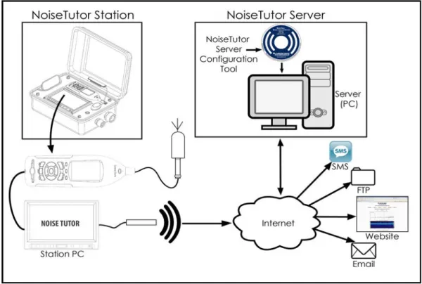
Figure 1-1 shows the components and architecture of the NoiseTutor System.
FIGURE 1-1 Components and Architecture - NoiseTutor System
Checking NoiseTutor Components
The NoiseTutor System is comprised of the following: 1. The NoiseTutor Station, including:
• Model 831 sound level meter • Station PC
• LCD display
• Compact, remote keyboard with trackball • Preamplifier
• Microphone
• Environmentally-sealed station case 2. NoiseTutor Server Configuration Software
The following table lists the components for the NoiseTutor Station model EPS041(NoiseTutor Accessory Kit) and NMS021 (complete NoiseTutor Kit including Model 831 Sound Level Meter):
The NoiseTutor Installation Reference is located inside your NoiseTutor station case and describes the assembly and operation of your station.
Optional Accessories
The following table lists the optional accessories for the NoiseTutor Station:
System Component
EPS041 Outdoor enclosure including gland for AC power and mic cable
EPS041 Compact Industrial PC With Windows 7 Pro®
EPS041 LCD Monitor
EPS041 Portable wireless keypad with trackball
EPS041 Cellular modem for cellular network access
EPS041 EXC020 20 ft. (6m) extension cable
EPS041 Lithium battery w/charger
EPS041 Quick Reference Guide, Installation Reference, and NoiseTutor Manual
EPS041 CD with starter software
NMS021 831-FF Type 1 Sound Level Meter
NMS021 PRM831 Preamplifier with 377B02 free-field polarized microphone
NMS021 831-LOG, 831-ELA and 831-OB3 firmware modules
NMS021 EPS2106 Microphone Protection Shroud
If you are using an outdoor preamplifier or a weather station, you can connect the power for either or both to the NoiseTutor Station by using connectors inside the case that are labelled “Accessories.” If using these accessories, you also need to order the Custom Cable Plug for the extra cable outlet in your NoiseTutor Station case.
Configuring the NoiseTutor Server
Larson Davis provides server configuration aids with the NoiseTutor System to provide web access to sound level monitoring sites. This includes the NoiseTutor Server Configuration Tool, which can be used with instructions in this manual to set up a server on a Windows®-based computer. The server consists of both a website--with a collection of pre-designed web pages--and an FTP site. The pre-designed server web pages present information from each monitoring site in the following forms:
• Ten-minute report • One-hour report • One-day report • One-week report • One-month report
Although you can use any web site server that is capable of rendering HTML pages with Java Script, the configuration
Component Part number
Instrumentation Tripod TRP003
Tripod Mounting Adapter EPS2106-2 to TRP003 (ADP034)
Basic Tripod TRP001
Outdoor Preamplifier PRM426A12
Weather Station SEN031
aids in this manual describe the steps for using Internet Information Services (IIS) from Microsoft. This manual describes configuration with IIS because it is currently the most common web server for Windows® operating systems and it is available at no cost.
Although the NoiseTutor system provides server configuration aids, you are responsible for setting up the web server.
You can also set up an FTP site on your server; in this way, you can collect noise monitoring data from Noise Tutor clients. This data can then be displayed in graphic reports for each monitoring site on a web site.
The process of installing and configuring the NoiseTutor Server involves complex and technical tasks, and generally requires the services of an IT professional. For your assistance, detailed instructions for installing and configuring the NoiseTutor Server on a Windows 7 platform are provided in this manual.
The NoiseTutor System also functions on Windows XP SP 3 and Windows Vista SP 1. However, the steps and options are different than those represented in this manual. To install and configure the NoiseTutor System on these platforms, Larson Davis recommends that you consult with an IT professional. Detailed instructions for setting up a server on other platforms are not available from Larson Davis.
System requirements for NoiseTutor Server
Configuration
• A PC system to be used as an FTP server
• Windows 7 SP 1, Server or Professional editions. Server edition is recommended.
• IIS 5.1 or higher
• One or more NoiseTutor Noise Monitoring Systems (NMS)
• Sound level meter serial number for each NoiseTutor station
Setting up the NoiseTutor Station
Start by reading the NoiseTutor
Quick Start Guide. It describes the steps for deploying your NoiseTutor Station.
To set up your NoiseTutor Station, refer to the NoiseTutor Quick Start Guide, the NoiseTutor Installation Reference, and this manual. These are located inside the NoiseTutor station case.
Installing NoiseTutor Station Software
The NoiseTutor Station software comes pre-installed when ordering the NMS-021 (with Model 831 sound level meters), and the EPS 041 (without Model 831 sound level meters). For other configurations, the software must be installed on the PC that is connected to the sound level meter. The software interacts with noise monitoring stations by downloading measured data from the sound level meters at predefined intervals. It then sends data or graphical reports to specified recipients. If your system does not include pre-installed software, refer to the instructions in "Station Installation and Setup".
System Requirements for NoiseTutor Station
Software
• Larson Davis sound level meter Model 831 • Windows 2000® or newer operating system
Larson Davis does not supply an active SIM card. You must obtain one separately.
C H A P T E R
2
Server Installation and
Setup
This chapter lists and describes the steps for setting up the NoiseTutor server on the Windows 7® operating system. To install the server, complete the following process:
1. Install IIS on Windows 7. 2. Configure the IIS web server. 3. Add Audio MIME Types.
4. Install the NoiseTutor Server Configuration Tool. 5. Run the NoiseTutor Server Configuration Tool. 6. Create an FTP user account.
7. Configure the Windows Firewall.
Each step is described in more detail in the following sections.
Before You Begin: The process of installing and config-uring the NoiseTutor Server involves complex and technical tasks, and generally requires the services of an IT profes-sional. These detailed instructions are provided for the con-venience of an IT professional working with your NoiseTutor System.
Installing IIS on Windows 7 Operating System
The NoiseTutor System also functions on Windows XP® SP 3 and Windows Vista® SP 1. However, the steps and options are different than those represented in this manual. To install and configure the NoiseTutor System on these platforms, Larson Davis recommends that you consult with an IT professional. Detailed instructions for setting up a server on other platforms are not available from Larson Davis. Installing the IIS add-in provides your host PC with both web- and FTP-server functionality. If you do not want to use IIS, you will need to supply your own web server and FTP server. To install IIS, follow these steps:
Step 1 On the Windows 7® Start menu, click Control Panel.
If the Programs and Features icon is not displayed in your Control Panel, click the drop down arrow in the address bar following the words “Control Panel.” Click All Control
Panel Items. The Programs and Features icon should then appear
with other icons in your Control Panel.
Step 2 Click Programs and Features.
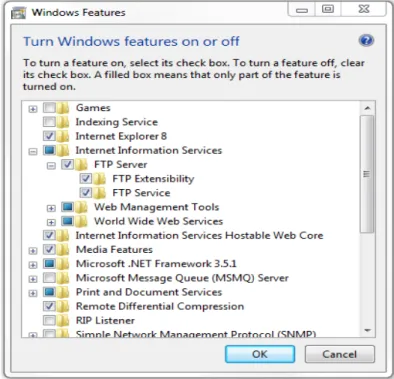
Step 3 On the left window border, click Turn Windows features on or off, as shown in FIGURE 2-1.
FIGURE 2-1 Turn Windows® Features On or Off
Step 4 Select Internet Information Services.
Step 6 Expand FTP Server. Select all items, as shown in FIGURE 2-2.
Step 7 Select Web Management Tools, as shown in FIGURE 2-2. Accept all defaults.
Step 8 Select World Wide Web Services, as shown in FIGURE 2-2. Accept all defaults.
Step 9 Click OK.Wait for Windows to make changes, as shown in FIGURE 2-3.
FIGURE 2-3 Microsoft Windows® - Please Wait
Step 10 Close Programs and Features.
Configuring the IIS Web Server
You can configure the IIS web server to set up your NoiseTutor web site. The following configuration places the web pages for your site in a virtual directory and sets the FTP server upload location as a subdirectory of that virtual directory. To set up your web site, follow these steps:
Step 1 Browse to c:\inetpub\wwwroot\ Click the New Folder button and name it LarsonDavis.
Step 2 Open inetmgr at the following location:
c:\windows\system32\inetsrv\inetmgr.exe.
Step 3 Expand the name of your computer.
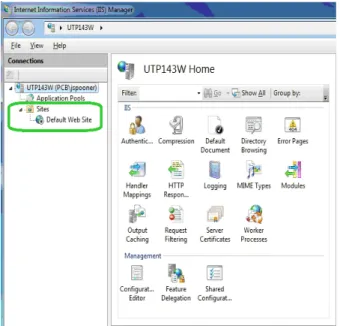
Step 5 Depending on your operating system, you may have the option of creating a new web site. Otherwise, you may be provided only with the default web site option, as shown in FIGURE 2-4.
FIGURE 2-4 IIS Manager - Expand Sites
Step 7 Select View Virtual Directories, as shown in
FIGURE 2-5.
FIGURE 2-5 IIS Manager - View Virtual Directories
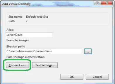
Step 8 Click Add Virtual Directory, as shown in FIGURE 2-6.
Step 9 In the Add Virtual Directory dialog box, Alias, type LarsonDavis in the Alias field, as shown in FIGURE 2-7.
Larson Davis strongly recommends that you specify, select, or accept all defaults for your configuration, as shown in this manual.
Step 10 For Physical path, specify LarsonDavis as the default root directory by typing the path as shown in FIGURE 2-7.
Step 11 Click Connect as…, as shown in FIGURE 2-7.
Step 12 In the Connect As dialog box, select the
Application user (pass-through authentication) option and click OK, as shown in FIGURE 2-8.
FIGURE 2-8 Connect As - Application User (pass through authentication)
Application user settings should not include errors, but can include warnings about being unable to verify access to the virtual directory. Such warnings are permissible because the user names and passwords are not available until the user accesses the web site.
Step 13 Select the application path and click Edit Permissions..., as shown in FIGURE 2-9.
Step 14 On the LarsonDavis Properties sheet, click the
Security tab, as shown in FIGURE 2-10.
Step 15 Select the user or group that will access the web site, as shown in FIGURE 2-10. Ensure the user or group has the following permissions:
A. Read & execute
B. List folder contents
C. Read
It is recommended that you not grant other permissions.
Step 16 Click Apply if you have made changes. Otherwise, click OK.
Step 17 Expand Default Web Site and double-click
LarsonDavis.
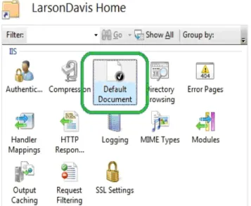
Step 18 Double-click Default Document, as shown in FIGURE 2-11.
FIGURE 2-11 IIS Manager - Default Document
Step 19 Remove all default documents except for
Step 20 If index.html is not present, click Add andin the
Add Default Document dialog box, type index.html and then click OK, as shown in FIGURE 2-12.
FIGURE 2-12 Add Default Document
Adding Audio MIME Types
If your NoiseTutor Station includes options for events and audio recording, with license files SWW-DNA-NT-EV and SWW-DNA-NT-CS, respectively, your web server must be configured for playing .ogg audio files. This is done by configuring MIME. If these options have not been purchased, this step can be skipped.
To add audio MIME types for supporting the audio recording feature, follow these steps:
Step 1 In the IIS Manager, double-click MIME Types, as shown in Figure 2-13.
FIGURE 2-13 IIS MIME Types
Step 2 In the MIMETypes list, click Add, as shown in Figure 2-14.
Step 3 In the Add MIME Type dialog box, type .ogg for the File name extension and type audio/ogg for MIME type, as shown in Figure 2-15.
FIGURE 2-15 Add MIME Type ogg
Step 4 Click OK.
Step 5 As shown previously, in the MIME Types list, click Add.
Step 6 In the Add MIME Type dialog box, type .ogx for the File name extension and type audio/ogx for MIME type, as shown in Figure 2-16.
FIGURE 2-16 Add MIME Type ogx
Installing the NoiseTutor Server Configuration
Tool
To install the NoiseTutor Configuration Tool, follow these steps:
Step 1 Insert NoiseTutor CD into your CD/DVD drive.
Step 2 If auto start is not enabled, Click [CD / DVD]\NoiseTutorConfigurationInstaller.exe.
Step 3 On the NoiseTutor Configuration Tool Setup Wizard, Click Next, as shown inFIGURE 2-17.
Step 4 Select the folder where you want to install the NoiseTutor Configuration Tool, as shown in FIGURE 2-18.
Step 5 Select either Everyone or Just me.
Step 6 Click Next to install the default installation folder.
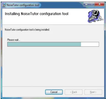
Step 7 To confirm the installation, click Next again. The wizard displays the installation progress as shown in FIGURE 2-19.
FIGURE 2-19 Configuration Tool - Installing NoiseTutor Configuration Tool
Step 8 Click Close.
Running the NoiseTutor Configuration Tool
The NoiseTutor Configuration Tool can be used to set up the following functionality on the server:
• Generate web pages.
• Request specific monitoring site information to populate web page templates.
• Generate and send graphical reports to a specified location.
You are responsible for assigning users and giving them the correct permissions to any FTP upload directories you create with the NoiseTutor Configuration Tool.
• Create an FTP directory for uploading site information. To run the NoiseTutor Configuration Tool, follow these steps:
Step 1 On the Start menu, click Computer. Browse to the ConfigurationTool.exe file, and double-click it, as shown in FIGURE 2-20.
A. For 64-bit Windows 7® operating systems, the file is located at c:\program files (x86)\PCB Piezotron-ics\NoiseTutor configuration tool\Configura-tionTool.exe.
B. For 32-bit Windows 7 operating systems, the file is located at c:\program files\PCB Piezotronics\Noi-seTutor configuration tool\ConfigurationTool.exe.
FIGURE 2-20 Configuration Tool - Launch
Step 2 If you are configuring a new site, click New Configuration on the File menu of the NoiseTutor Site
Step 3 If you are modifying an existing configuration, click Open Configuration on the File menu.
Step 4 From the Open dialog box, browse to the location of your existing site configuration file (.csf) and double-click it.
Step 5 For Monitoring Site information, provide decimal values for the Latitude and Longitude coordinates of your site, as shown in FIGURE 2-21. Refer to Google Maps, or another map service for help in finding these values for your site.
FIGURE 2-21 Configuration Tool - Information Launch3
Step 6 For Zoom, type a numeric value for the zoom level of the Google map to display for your site. The number you specify corresponds to the Google Maps designation of zoom levels, where zero (0) displays a map of the world and 21displays an individual building. Larson Davis provides a default value of 12.
Step 7 For Sound Level Meter, specify the Type as model
Step 8 For Serial Number, specify your sound level meter serial number. You can find the serial number by turning on your meter with the 0 (ON/OFF) button, pushing the 3 (TOOLS) key, scrolling to the About folder, selecting the folder by pressing 1 (ENTER), and retrieving the number displayed in the Instrument Information section.
Step 9 Provide the appropriate information for the remaining fields in this dialog box.
Step 10 Repeat steps one through six for each site, as needed.
Step 11 On the File menu, click Save Configuration.
Step 12 On the Generate Sites menu, click No Events if your system does not include Event Detection as a feature. Event Detection is an optional feature that requires a purchased license file to operate. If you have purchased the license file, click With Events. This step creates the web files for the configuration.
Step 13 In Browse for Folder, click the folder location that you specified for your virtual directory.
Step 14 For Confirm Delete, click Yes to delete current web files. All previous files in the virtual directory are deleted prior to regenerating the new files. Click No to leave all previous files during generation. Duplicate files are overwritten.
Step 15 For Successful Generation, click OK.
Step 16 To close NoiseTutor Site Configuration Tool, click
Exit on the File menu.
Creating User Accounts for FTP Uploads
You can create user accounts for your FTP client to authenticate itself with an FTP server. User accounts should have write access permissions to the FTP server
UploadImages folder, and any sub-folders, but any additional rights are best left restricted. To create a user account, follow these steps:
Step 1 On the Start menu, click Control Panel.
If Administrative Tools is not displayed in your Control Panel, click the drop down arrow in the address bar following the words “Control Panel.” Click All Control
Panel Items. The Administrative Tools icon should appear with other
icons in your Control Panel.
Step 2 Click Administrative Tools.
Step 3 Double-click Computer Management.
Step 4 Expand Local Users and Groups.
Step 5 Click the Users folder, as shown in FIGURE 2-22.
FIGURE 2-22 Computer Management - Users
Larson Davis strongly recommends that you specify, select, or accept all defaults for your configuration, as demonstrated in this manual.
Step 7 In the New User dialog box, provide the user name, full name, description; also, create a password as shown in FIGURE 2-23. The default name for user accounts is UploadUser. Do not select any additional options on this dialog box.
Step 8 Click Create.
\
FIGURE 2-23 New User - Create
Step 10 Click the name of the user account, or the default name UploadUser, if applicable, as shown in FIGURE 2-24.
FIGURE 2-24 Computer Management - Upload User
Step 11 Provide the user account with the appropriate permissions to the FTP upload folder UploadImages and its sub-folders. This folder is a sub-folder in your NoiseTutor virtual directory. Permission options may vary but should include write access. It is best to restrict permissions to only the UploadImages folder and any sub-folders.
Step 12 On the Actions menu, click Properties.
Step 14 On the Properties dialog box, select any entries listed under Member of: and click Remove, as shown in FIGURE 2-25.
FIGURE 2-25 UploadUser Properties - Member of
Step 15 Click Apply.
Step 16 Click OK.
Step 17 To close the Computer Management screen click
Exit on the File menu.
Step 18 Close the Administrative Tools screen and the Control Panel.
Step 19 From the Start menu, click Computer.
Step 20 Browse to the default virtual directory at
c:\inetpub\wwwroot\LarsonDavis\UploadImages, as specified in Step 7.
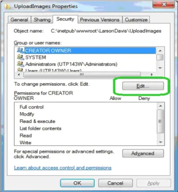
Step 22 On the Properties dialog box, click SecurityTab.
Step 23 Click Edit…, as shown in FIGURE 2-26.
Step 24 On the Permissions dialog box, click Add..., as shown in FIGURE 2-27.
FIGURE 2-27 Permissions for UploadImages - Add
Step 25 In the Enter the object names to select, type in the name of the user account, or the default name
UploadUser, if applicable, as shown in FIGURE 2-28.
Step 26 Make sure the From this location references your computer.
Step 27 Click CheckNames.
Step 28 Click OK on both dialog boxes.
Step 29 On the Security tab of the Properties dialog box, click the user account name, or the default name
UploadUser, if applicable, as shown in FIGURE 2-29.
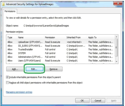
Step 30 Click Advanced.
Step 31 On the Advanced Security Settings dialog box, click the Permissions tab.
Step 32 Click the user account name, or the default
UploadUser, if applicable, as shown in FIGURE 2-30.
Step 33 Click Change Permissions….
Step 34 Click Edit..., as shown in FIGURE 2-31.
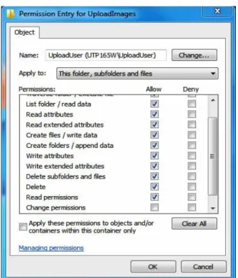
Step 35 For Permission Entries, select the following
Allow rights, as shown in FIGURE 2-32:
• List folder/read data • Read attributes
• Read extended attributes • Create files/write data • Create folders/append data • Write attributes
• Write extended attributes • Delete sub-folders and files • Delete
• Read permissions
FIGURE 2-32 Permissions Entry for UploadImages - Upload User
Setting up FTP Servers
Setting up an FTP server allows you to upload the
NoiseTutor client reports. The FTP server root folder should be specified as the sub-folder “UploadImages” for the web server. To set up the FTP server, follow these steps:
Step 1 From the Start menu, click Computer. Browse to
c:\windows\system32\inetsrv\inetmgr.exe.
Step 2 Double-click inetmgr:
Step 3 Under Connections on the Internet Information Services (IIS) Screen, click the local computer icon to expand it, as shown in FIGURE 2-33.
Step 4 Click ContentView, as shown in FIGURE 2-33.
Step 5 Click Add FTP Site…, as shown in FIGURE 2-33.
Step 6 On the Site Information page of the Add FTP Site wizard, type Upload Images FTP Site for the FTP site name, as shown in FIGURE 2-34.
Step 7 Under Physical path: type
c:\inetpub\wwwroot\LarsonDavis\UploadImages, as shown in FIGURE 2-34,or browse to the folder and select it.
Step 8 Click Next.
Step 9 On the Binding and SSL Settings page, Select All Unassigned for IP Address, as shown in FIGURE 2-35.
Step 10 Specify the port for the FTP site, as shown in FIGURE 2-35. The default is 21.
Step 11 Clear the EnableVirtualHostNames: option.
Step 12 Select StartFTPSiteAutomatically.
Step 13 Select NoSSL.
Step 14 Click Next.
FIGURE 2-35 Add FTP Site - Binding and SSL Settings
Step 15 On the Authentication and Authorization Information page, select Basic for Authentication.
Step 16 Select SpecifiedUsers for Allow access to:
Step 17 Type in your user account name, or thedefault
UploadUser, if applicable, as shown in FIGURE 2-36.
Step 18 Select Read and Write under Permissions.
Step 19 Click Finish.
FIGURE 2-36 Add FTP Site - Authentication and Authorization Information
Step 20 Close IIS.
Configuring Windows Firewalls
Firewalls are used to restrict remote access to your computer. If you have a firewall present, you will need to allow web and FTP access. Below is an example for configuring Windows® Firewalls. For other firewalls, refer to the documentation from that provider.
If Windows Firewall is not displayed in your Control Panel, click the drop down arrow in the address bar following the words “Control Panel.” Click All Control Panel
Items. The Windows Firewall icon
should appear with other icons in your Control Panel.
Step 2 Click Windows®Firewall.
Step 3 Click AdvancedSettings, as shown in FIGURE 2-37.
FIGURE 2-37 Windows Firewall - Advanced Settings
Step 4 On the Windows Firewall with Advanced Security screen, click InboundRules, as shown in FIGURE 2-38.
FIGURE 2-38 Windows® Firewall with Advanced Security - New Rule
Step 6 On the Rule Type page of the New Inbound Rule Wizard, select Predefined: as shown in FIGURE 2-39.
Step 7 Select FTP Server, as shown in FIGURE 2-39.
Step 8 Click Next.
Step 9 On the Predefined Rules page, select FTP Server Passive (FTP Passive Traffic-In), as shown in FIGURE 2-40.
Step 10 Select FTP Server Secure (FTP SSL Traffic-In), as shown in FIGURE 2-40.
Step 11 Select FTP Server (FTP Traffic-In), as shown in FIGURE 2-40.
Step 12 Click Next.
Step 13 On the Action page, select Allow the connection, as shown in FIGURE 2-41.
Step 14 Click Finish.
FIGURE 2-41 Windows® Firewall - New Inbound Rule Wizard - FTP (Allow the connection)
Step 15 On the Windows Firewall with Advanced Security screen, click InboundRules, as shown in FIGURE 2-42.
FIGURE 2-42 Windows® Firewall with Advanced Security - New Rule
Step 17 On the Rule Type page, select Predefined:, as shown in FIGURE 2-43.
Step 18 Select World Wide Web Services (HTTP), as shown in FIGURE 2-43.
Step 19 Click Next.
Step 20 On the Predefined Rules page, select World Wide Web Services (HTTP Traffic-In), as shown in FIGURE 2-44.
Step 21 Click Next.
Step 22 On the Action page. select Allow the connection, as shown in FIGURE 2-45.
Step 23 Click Finish.
FIGURE 2-45 Windows® Firewall - New Inbound Rule Wizard - Allow the Connection
Step 24 Close the Windows Firewall with Advanced Security screen.
Step 25 Close the Windows Firewall.
Verifying Access to FTP Servers
Local Access
Verify your access to the FTP server from your server (local), by following these steps:
Step 1 Make sure the FTP server is running. Click Start
in IIS if it is not, as shown in FIGURE 2-46.
FIGURE 2-46 IIS Manager - FTP Server Running
Step 2 Verify that the user name and password are valid for the server. If not, use the user name and password supplied by the administrator, or add the user name and password to a user account for the server machine.
Local Network Access
Verify your access to the FTP server from another machine on the same network, by following these steps:
Step 1 Follow the steps for verifying that your server can access the FTP server.
Step 2 Verify that the FTP server's firewall allows FTP traffic, as shown in FIGURE 2-47.
FIGURE 2-47 Windows® Firewall with Advanced Security - FTP Services Allowed
Step 3 Type your IP address into the address bar of your browser. Verify that the browser loads correctly, as described in the following section.
Public Access
If you have a public FTP firewall on your network, you will need help from your network administrator.
Verify your access to the FTP server from another network (public), by following these steps:
The FTP site address must be publicly accessible to receive data.
Step 1 Follow instructions in Accessing FTP server from another machine on the same network.
Step 2 Verify that the router has port forwarding or port triggering rules for the FTP port, as shown in FIGURE 2-48.
FIGURE 2-48 Router Port Forwarding - FTP Service
Verifying Browser Connections
To verify your browser is connected and loads correctly, follow these steps.
Step 1 Verify that the website is available on the web server.
Step 3 In the address bar, type http://localhost/ LarsonDavis/index.html.
Step 4 If the main web page does not appear, verify that the web service is running. Click Start in IIS if it is not, as shown in FIGURE 2-49.
Step 5 Verify that the proxy user or supplied user has read access permissions, as shown in FIGURE 2-50. If not, grant read access to the proxy user or supplied user.
Step 6 Verify that the file index.html is located in the virtual directory, as shown in FIGURE 2-51. If not, run
ConfigurationTool.exe again.
Step 7 To ensure access to your web site from another computer, verify that the server's firewall allows traffic through the web site port (Default 80), as shown in FIGURE 2-52. Change the firewall if needed.
FIGURE 2-52 Windows® Firewall With Advanced Security - World Wide Web
If your web server does not have a public IP address, you will need to configure your routers for access. Consult with your organization’s IT professional for help.
Step 8 To ensure access to your website from the Internet (and not just your local network), verify that the router has port forwarding or port triggering rules for your web site.
C H A P T E R
3
Station Installation and
Setup
This chapter provides instructions for setting up the NoiseTutor Station, including software, licenses, settings, preferences, and data communication. It is recommended that you perform the procedures in the order they are presented in the following sections.
Installing NoiseTutor Software
Important: The NoiseTutor software
comes pre-installed when NoiseTutor is purchased as a system. If you purchased a system, skip to the following section, "Starting the NoiseTutor Station" on page 3-3.
If your NoiseTutor Station was not purchased as part of a system, or if for some other reason you need to install the NoiseTutor software, insert the CD into your station computer (not the server computer) and follow the instructions on the installation wizard.
During the setup process, a link to the NoiseTutor software is created in the Startup folder of the Windows® operating system. As a result, the NoiseTutor software runs every time Windows is started. It also enables the NoiseTutor Station to automatically restart Windows without user intervention. The link to the Windows Startup folder starts the NoiseTutor System as a program, but it does not automatically start monitoring operations. If Windows is restarted while the NoiseTutor System is opened and running (see Main Commands), the program stores the previous state, and upon restart it reactivates the monitoring operations.
If you want the monitoring operations to start automatically each time the Windows® operating system starts up, follow these steps:
Step 1 Browse to the NoiseTutor link in the Windows Startup folder.
Step 2 Right-click the NoiseTutor icon and click Properties, as shown in FIGURE 3-1.
Step 3 In the Target field, replace C:\Program Files\NoiseTutor\NoiseTutor.exe with C:\ProgramFiles\ NoiseTuto\NoiseTutor.exe -R, as shown in FIGURE 3-2.
FIGURE 3-2 NoiseTutor Properties
Starting the NoiseTutor Station
Refer to the NoiseTutor Quick Start Guide and the NoiseTutor Installation Reference on the inside of the NoiseTutor System case to set up your hardware.
With the necessary hardware installed, follow these steps to start the NoiseTutor Station:
Step 2 Press the monitor power button to activate the display.
Step 3 Remove the keyboard and slide the keyboard switch to ON.
Note: Slide the keyboard switch to
OFF when not in use.
Step 4 Verify that the network utility has connected to a cell network.
Step 5 When the wireless modem utility has connected to the cell network, minimize the utility.
Installing NoiseTutor Station Licenses
Your license may be pre-installed if you receive a new sound level meter as part of your NoiseTutor Station.
The NoiseTutor Station requires an activation license in order to be used. The license files you receive is based on the model and serial number of the sound level meter. Please contact PCB Technical Support to obtain license files. To install the license file, follow these steps:
If you received the license file as a zipped file, remember to unzip it first. Otherwise, NoiseTutor will not recognize it as a license file.
Step 1 Copy all license files you receive from PCB to your clipboard. Your license files may be sent to you through e-mail. If you receive them by some other method and are copying your license using USB flash memory, disconnect the USB switch and insert your memory into that drive. Do not disconnect the USB keyboard dongle to insert your USB flash memory. This is shown on the Installation Reference located on the inside of the front cover of the station case.
Step 2 Launch the NoiseTutor Software.
The license file is named in the following format: NT_831_LxT_XXXX.lic, where XXXX represent the last four numbers of the sound level meter serial number being used in the system.
Step 3 From the View menu, click NoiseTutor Folder.
If your are copying your license using USB flash memory, disconnect the USB switch and insert your memory into that drive. Do not disconnect the USB keyboard dongle to insert your USB flash memory.
If your license was not factory installed for your sound level meter and you received it via another method, copy the file from the source where you receive it and paste it according to the directions provided above.
You can check the status of your license files by clicking
Help and then clicking About NoiseTutor.... The license status window is shown in Figure 3-3.
Checking Battery Status
If the Model 831 is ON, pressing the
0
(ON/OFF) key displays the Power Control screen, as shown in Figure 3-4.On the Power Control Screen, the values associated with “Estimated Run Time,” “Battery Type,” and “Battery” are not applicable to the NoiseTutor station and should be disregarded while the sound level meter is part of the station.
FIGURE 3-4 Power Control Screen
To check the voltage of the battery, refer to the value indicated next to “Ext Powered.”
Make sure you recharge the battery before the value on the Ext Powered display indicates 10 volts or less. The station shuts down automatically at 10 volts.
The fully-charged lithium ion battery for the NoiseTutor station carries 14.8 Volts; when the battery depletes to 10 volts, the sound level meter powers off. You can also check the battery condition by pressing the switch button on the front of the battery. Refer to the battery manual for more information.
Checking the Station PC Power Settings
To check the power settings on the Station PC in the NoiseTutor station, follow these steps:
The settings in this section are the default power saving options for the Station PC. If your Station PC has had its settings altered, you can follow the steps in this section to restore the default settings.
Step 1 From the Start menu, click Control Panel.
Step 2 Click Power Options.
Step 3 Specify the default time settings as shown in Figure 3-5.
Step 4 Click Change advanced power settings, as shown in Figure 3-6.
FIGURE 3-6 Advanced Power Settings
Step 5 On the Advanced Settings tab, expand Battery
and Critical battery action. For the On battery entry, specify Shut down if not already selected; for the Plugged in entry, specify Do nothing if already not selected. The settings are shown in Figure 3-7.
Step 6 On the Advanced Settings tab, expand USB Settings and USB Selective Suspend Setting. For the On battery entry, specify Disabled if not already selected; for the Plugged in entry, specify Enabled if not already selected. The settings are shown in Figure 3-8.
FIGURE 3-8 USB Settings
Step 7 If you made any changes, click OK on the
Advanced Settings tab and then click Save changes on the Power options dialog box
Restoring Settings for Automatic Wakeup
Your NoiseTutor Station is shipped with automatic wakeup already configured. If this setting has been altered, you can restore it by following these steps:
Step 1 Click Control Panel > Power Options > and then click Change advanced power settings as shown
previously in Figure 3-6.
Step 2 On the Advanced Settings tab, expand the fit-PC2 setting and then expand Require a password on wakeup.
Step 3 For both On battery and Plugged in settings, select No.
Step 4 Expand the Sleep setting from the same list on the
Advanced Settings tab and then expand Allow wake timers.
Step 5 For both On battery and Plugged in settings, select Enable.
Step 6 Click Apply and then click OK.
FIGURE 3-10 Wakeup Timer Setting
Step 7 Launch the NoiseTutor software and click Setup >
Working Mode > Data File.
Step 9 In the Main Setup dialog box, select Standby in the Power saving drop-down list.
FIGURE 3-11 Standby Power Saving Setting
Checking the NoiseTutor Model 831 Run
Preferences
To check the Run preferences on the model 831 in the NoiseTutor station, follow these steps:
Step 1 Press the softkey under Menu on the model 831 display.
Step 2 Select Settings and press
5
.Step 3 Press
5
again on Yes to confirm Settings in use by PC.Step 5 Check the Run Mode and Auto-Store Preference selections. The default settings are shown in Figure 3-12.
You can specify other Run preferences on the Control tab, such as Enable Measurement History or Cal-Check, without affecting the default Run preferences described here.
FIGURE 3-12 Model 831 Run Preferences
To modify the Run preferences for the model 831, scroll to
Run Mode or Auto-Store, as shown in Figure 3-12, and select the desired option from the drop down menu, and then press
5
.Monitoring the Wireless Modem Connection
The NoiseTutor station includes the Sierra Wireless®AirLink LS300 modem. Additionally, the Sierra Wireless ACEview utility is installed on the Station PC for monitoring the status of the wireless connection. Figure 3-13 shows the ACEview icon as it appears on the Station PC desktop:
FIGURE 3-13 ACEview Modem Utility Icon
Refer to the Sierra Wireless AirLink LS300 User Guide and the ACEview User Guide for more information on the wireless modem and the ACEview utility.
Specifying Main Application Settings
Before configuring NoiseTutor Station data delivery features, the main applications settings must be specified in the Main Setup dialog box.
FIGURE 3-14 shows the Main Setup dialog box.
FIGURE 3-14 Main Setup
To specify the main settings, follow these steps:
Step 1 Specify the Working Mode. On the Setup menu, click Working mode and then click either Data File or
Data File + Realtime Reports. The Data File option configures NoiseTutor to e-mail data files; the Data File + Realtime Reports option configures NoiseTutor to deliver both data files and graphical reports via e-mail.
Step 2 On the Setup menu, click Main Setup.
Step 3 Refer to FIGURE 3-14 while entering the following information:
• Station name: Type the name of your monitoring station.
• Store Folder: Specify the folder on the local hard disk where the downloaded files are to be saved. To select locations other than the default, click the ... button and navigate to the new location.
• Select the zip files before sending to mail or ftp option to send compressed files. Zipping files is recommended.
• Check Instrument Time: Specify how often the Station PC should check the sound level meter internal clock to verify synchroniztion with the PC clock. Checking the internal clock does not require a stop in measurement, but changing the internal clock requires a stop. Choose between the following options:
• Never • Every download • 1 day • 2 days • 3 days • 4 days • 5 days • 6 days • 7 days
• Update when difference is greater than: Specify the value, in seconds, when the difference between the instrument internal clock and the Station PC clock merits updating the internal clock.
• Spectrum extension: Specify the octave spectrum size to be measured. Choose between 20Hz-20kHz or Full Spectrum.
• Check for new files: Specify a time period for the Station PC to wait between download operations. If the
Synchronize option is selected, the download time is synchronized at the specified hour, starting from midnight.
Do not select Hibernate power saving mode. Selecting this mode prevents the Station PC from waking up.
• Power saving: Specify the Station PC mode for wait times between downloads. Select None if no power saving is needed. Select Standby mode to enable power saving and put data in memory without turning off the computer. This Power saving field is disabled if the working mode is set to “Realtime Report.”
• Restart Windows every: Specify the number of days that the Station PC should wait before rebooting on a regular basis. This may be helpful because the Windows® operating system can become unstable if the system operates for long periods of time.
• Send the PC to “Standby” when waiting for more than 5 minutes: Select this option to enable the PC to enter standby between downloads. This field is disabled if the working mode “Realtime Report” is enabled. • Keep the PC on for remote maintenance connection:
Select these options to have the Station PC shut down during two time periods every day, independently of download times, so that administrative tasks can be performed remotely.
• For Period 1 Starting from: specify a beginning time in 24-hour notation for when the Station PC should be turned on.
• For Duration: specify the duration of time the Station PC should be turned on. The times specified for this setting are referenced by the internal clock time on the Station PC, regardless of actual time.
• If an additional time period is needed, specify the time and duration for Period 2 in the same manner as specified for Period 1.
• For remote operation, choose any remote software package that is compatible with Windows 7®. • If you are using a dial-up connection with a
wireless modem, you may need to set the dial-up software to automatically connect when Windows is started.
Step 4 Click OK.
Configuring Data Transmission and Delivery
Settings
Configuring data transmission and delivery settings for the NoiseTutor Station includes the following procedures: 1. Setting up SMTP and SMS Messaging Services 2. Adding E-mail and SMS Recipient Lists
The NoiseTutor Station does not support SSL connections for SMTP (e-mail).
3. Specifying Data Settings for E-mail Messages 4. Setting up Data Delivery for FTP Server Sites 5. Specifying Real-time Report E-mail Settings
6. Creating and Publishing Graphical Reports to Websites 7. Updating Webpages from the NoiseTutor Station The following two sections describe the procedure for configuring these services.
Set Up SMTP (E-mail) Service
To deliver data files and graphical reports via e-mail, you must first configure SMTP service settings on the NoiseTutor Station.
To set up the NoiseTutor Station for SMTP (e-mail) service, follow these steps.
For more information on SMTP setup, refer to "Messaging" on page 5-8.
Step 1 On the Setup menu, click Messaging < SMTP.
Step 2 Refer to FIGURE 3-15 while entering the following information:
FIGURE 3-15 SMTP (E-mail) Setup
• SMTP mail server: Specify the name of your SMTP mail server. Usually, this address is provided by your internet service provider.
• Send Address: Specify the e-mail address to be used to send data files and that is hosted by the SMPT mail server specified.
• Use E-mail authentication: Select this option if your SMTP mail server requires a Login name and Login password.
If you set up the NoiseTutor Station to e-mail data files, the graphs in the message are based on the data file. If you want to view spectral data in the message, you must enable logging for spectral data on the sound level meter. See the technical reference manual for your sound level meter for more information.
• SMTP Port: Specify the port number reserved for mail by your organization. Consult with your network administrator to verify the correct number.
• Login Name and Login Password: Specify the login name and password you want to use to access e-mail on your SMTP mail server, if authentication is requested. • In the Information request address field, type the
e-mail address of the designated personnel to handle data inquiries.
• Send test e-mail...: Provide an address to send a test message. After sending, the Station PC displays the results and content of the SMTP test.
Step 3 Click OK.
Set Up SMS (Text Messaging) Service
To deliver sound level information through text messaging, you must first configure SMS service settings on the NoiseTutor Station.
To set up the NoiseTutor Station for SMS (text messaging), follow these steps.
For more information on SMS setup, refer to "Messaging" on page 5-8.
Step 2 Refer to FIGURE 3-16 while entering the following information:
SMS service, when used with the Event Detection feature, can be helpful in providing notification of specified events. For more information, see "Event Detection" on page 5-19.
FIGURE 3-16 SMS Setup
• Mobile phone or modem port: Specify the COM port where the mobile phone or modem is connected. Access is always through a COM port, even with integrated modems. The correct number may be found through the Device Manager in Windows 7®.
• Baud-rate: Specify the desired communication speed between the Station PC and the device.
• SIM card activation PIN: Type the PIN of your SIM card. Leave this field empty if the PIN request is not activated or not needed for your SIM.
• Send test SMS...:Sends a test SMS, or text message. After sending, the Station PC displays the results and content of the SMS test.
Add E-mail and SMS Recipient Lists
The NoiseTutor Station uses recipient lists to send sound level data. To add recipient lists, follow these steps:
For more information on setting up and specifying recipient lists for e-mail and text messaging, see "Recipient Lists" on page 5-6.
Step 1 On the Setup menu, click Recipient Lists.
Step 2 On the Recipient Lists dialog box, click the New list button in the lower left corner of the dialog box.
Step 3 For List name, type the name of the new recipient list, as shown in FIGURE 3-17.
FIGURE 3-17 Recipient List Set-up
Step 4 To add e-mail and SMS information for a recipient on the list, click the Add... button.
Step 5 On the Recipient dialog box, type the Name, E-mail address and SMS number of the recipient to be added to the list.
Step 6 Click OK and repeat this step for every recipient you want to add to the list.
Step 7 Click the New List button to create additional recipient lists, as shown in FIGURE 3-17.
Step 8 Click OK to exit the Recipient Lists dialog box.
Specify Data Settings for E-mail Messages
The NoiseTutor Station can send both data files and graphical reports via e-mail. First, you must set up the SMTP Service settings for the NoiseTutor Station, as described previously. After setting up SMTP service, you specify the content, or data, to be included in e-mail messages.
To specify the data to be included in e-mail messages, follow these steps:
Step 1 On the Setup menu, click Data File, and then click E-mail 1…. This launches the E-mail Data File 1 Service Setup dialog box, as shown in FIGURE 3-18.
Step 2 Select Enable E-mail data file …, as shown in FIGURE 3-18.
Step 3 For Recipients list, select the recipient list to which the sound level data will be sent.
Step 4 For Subject, type the subject title.
Step 5 For Message text, type the e-mail message.
For more information on Time History graphs and Sonograms, see "Graph" on page 5-11.
Step 6 In the Attachments section, select the graphic report attachment to include in the e-mail. You can select
Time History 1, or Sonogram, or both.
Step 7 Specify the height and width dimensions for the graphs in the attachments.
You can view Slmdl data files in the SLM-G3 Utility software.
Step 8 Select Slmdl Data File to attach the data file from the NoiseTutor Station sound level meter.
Audio files can also be sent via e-mail when specified events are detected by the NoiseTutor Station. For more information, see "Event Detection" on page 5-19.
Step 9 Select the Include the PC power status information to include the Station PC power information.
Step 10 Click OK.
Step 11 Verify that Internet Upload on the Commands
menu is checked.
Step 12 Configure other NoiseTutor data transmission options and begin taking sound level data by clicking Start
on the Commands menu.
Step 13 To setup a second e-mail service, click Setup < Data File < Email 2... and repeat the previous steps.
Specify Real-Time Report E-mail Settings
The NoiseTutor Station can send real-time graphical reports via e-mail. After setting up SMTP service, you specify the real-time reports to be included in e-mail messages. To specify the data to be included in e-mail messages, follow these steps:
Step 1 On the Setup menu, click Realtime Report, and then click E-mail 1…. This launches the E-mail Report Service Setup dialog box, as shown in FIGURE 3-19.
FIGURE 3-19 Realtime Report E-mail Service Setup
Step 2 Select Enable E-mail report service, as shown in FIGURE 3-19.
Step 3 For Recipients list, select the recipient list to which the real-time report is to be sent.
Step 5 For Message text, type the e-mail message.
Step 6 For Send report every, specify how often the real-time report is to be sent.
For more information on Time History graphs and Sonograms, see "Graph" on page 5-11.
Step 7 In the Graphic report to attach section, select the graphic report attachment to include in the e-mail.
Step 8 Specify the height and width dimensions for the graphs in the attachments.
Step 9 Click OK.
Step 10 Verify that Internet Upload on the Commands
menu is checked.
Step 11 Configure other NoiseTutor data transmission options and begin taking sound level data by clicking Start
on the Commands menu.
Step 12 To setup a second real-time report e-mail service, click Setup < Realtime Report < Email 2... and repeat the previous steps.
Set up Data Delivery for FTP Server Sites
To publish graphical reports from FTP sites to websites, first set up data delivery on your FTP site, as described in this section, and then see the following section, "Create and Publish Graphical Reports to Websites" on page 3-27.
By setting up an FTP site for data delivery, you can do the following:
• Receive sound level data files
• Publish graphical reports of data files on websites • Publish realtime reports of sound measurements on
websites
• Receive and publish event detection reports
• Receive and post audio recordings of measurements to websites
• To set up data delivery for FTP sites, follow these steps:
If you have a public FTP firewall on your network, you will need help from your network administrator.
Step 1 Specify the Working mode. On the Setup menu, click Working mode and then click either Data File or
Data File + Realtime Reports. The Data File option configures NoiseTutor to deliver only data files to FTP
sites; the Data File + Realtime Reports option allows both FTP data file delivery and real-time report e-mail and web publishing features.
Step 2 On the Setup menu, click Data File and then click
FTP 1… This launches the FTP 1 Service Setup dialog box, as shown in. FIGURE 3-20.
FIGURE 3-20 FTP Service Set-up
Step 3 On the FTP1 Service Setup dialog box, select the
Enable the FTP1 service option.
The FTP site address must be publicly accessible to receive data.
Step 4 Specify an FTP site address by typing your user IP address or the local host IP address.
Larson Davis strongly recommends that you specify, select, or accept all defaults for your configuration, as demonstrated in this manual.
Step 5 Type the default FTP site User name UploadUser.
Step 6 Type an FTP site password.
Step 7 If you have specified the default values in configuring your server, as shown in this manual, type a forward slash (/) for Folder name. This specifies your virtual directory. Otherwise, type the path to the location you have specified in configuring your server.
Step 8 Click OK.
Step 9 Verify that Internet Upload on the Commands
Step 10 Configure other NoiseTutor data transmission options and begin taking sound level data by clicking Start
on the Commands menu.
Create and Publish Graphical Reports to Websites
Note: The NoiseTutor Station View menu enables the display of log files, where operations are recorded. It also enables the log of Internet connection statistics, or the logs of debug messages. Such log files can be helpful in debugging wireless modem dial-up connections.
To create and publish reports of sound level data to websites, follow these steps:
Step 1 Create a website that accepts graphical reports. This can be done using the NoiseTutor Server Configuration Tool located on the NoiseTutor CD.
Step 2 On the Setup menu, click Working Mode. Select
Realtime Report to deliver only graphical reports to a web site. Select Data File + Realtime Report to deliver both data files and graphical reports.
Step 3 On the Setup menu, clickRealtime Report and then click Web1…. This launches the Web Report Service Setup dialog box, as shown in Figure 3-21.