International Journal of Research in Engineering & Applied Sciences 1 http://www.euroasiapub.org
ANALYSIS
OF
PATCH
ANTENNA
FOR
PARAMETER
ENHANCEMENT
AT
1.911
GHZSachin Chalisgaonkar* Santosh Sharma**
ABSTRACT
In this paper work, A patch antenna and our proposed metamaterial patch antenna are simu-lated and compared. A rectangular microstrip patch antenna along with the innovative metama-terial structure is proposed at a height of 3.2mm from the ground plane. This work is mainly fo-cused on increasing the potential parameters of microstrip patch antennas and analyzing the dual band operation of proposed antenna.This structure produces a better performance com-pared to simple RMPA. The implementation of the metamaterial as the substrate in a rectangular microstrip patch antenna produces high value of return loss.
Rectangular Microstrip Patch antenna loaded with metamaterial (MTM) is proposed for better improvement in the impedance bandwidth and reduction in the return loss at operating frequen-cy 1.911 GHz. The proposed antenna is designed at a height 3.2 mm from the ground plane. At 1.911 GHz, the bandwidth is increased up to 27.2 MHz in comparison to RMPA alone of bandwidth 6.5 MHz. The Return loss of proposed antenna is reduced by -19.15dB. Microstrip Patch antenna has advantages than other antenna is lightweight, inexpensive, easy to fabricate and achieve radiation characteristics with higher return loss. CST MICROWAVE STUDIO is used to design the metamaterial based rectangular microstrip patch antenna.
Keywords- Rectangular microstrip patch antenna (RMPA), Metamaterial (MTM) Impedance Bandwidth, Return loss.
IJREAS
Volume 3, Issue 7 (July 2013) ISSN: 2249-3905
International Journal of Research in Engineering & Applied Sciences 2 http://www.euroasiapub.org
I. INTRODUCTION
In modern wireless communication systems, the microstrip patch antennas are commonly used in the wireless devices. Therefore, the miniaturization of the antenna has become an important issue in reducing the volume of entire communication system [1].
Microstrip antennas are largely used in many wireless communication systems because of their low profile and light weight [2].
The “patch” is a low-profile, low –gain, narrow – bandwidth antenna. Aerodynamic considera-tions require low-profile antenna on aircraft and many kinds of vehicles. Typically a patch con-sists of thin conducting sheet about 1 by 1/2λ0 mounted on Substrate. Radiation from the patch is like radiation from two slots, at the left and right edges of the patch. The “slot” is the narrow gap between the patch and the ground plane. The patch –to-ground-plane spacing is equal to the thickness t of the substrate and is typically about λ0/100. Advantage of patch antenna than sever-al antenna is lightweight and inexpensive. The electric field is zero at the center of patch, maxi-mum at one side, minimaxi-mum on the opposite side. The important parameters of any type antenna are impedance bandwidth and return loss. The impedance bandwidth depends on parameters re-lated to the patch antenna element itself and feed used. The bandwidth is typically limited to a few percent. This is a disadvantage of basic patch antenna. Metamaterial based rectangular mi-crostrip patch antenna improves the bandwidth and return loss in significant way. CST MI-CROWAVE STUDIO is a software package for the electromagnetic analysis and design, use to design the metamaterial based rectangular microstrip patch antenna. The software contains four different simulation techniques like transient solver, frequency domain solver, integral equation solver, Eigen mode solver and most flexible is transient solver.
V.G. Veselago in 1968 provided a theoretical report on the concept of metamaterial (MTM) [3]. A Left- Handed metamaterial or double-Negative Metamaterial exhibits negative permittivity and permeability [4]. The currently popular antenna designs suitable for the applications of wire-less local area network (WLAN) and world- wide interoperability for microwave access (Wi-MAX) have been reported [5].
II. DESIGN SPECIFICATIONS
International Journal of Research in Engineering & Applied Sciences 3 http://www.euroasiapub.org
Calculation of Width (W):
(1) Where
C = free space velocity of light,
r =Dielectric constant of substrate
The effective dielectric constant of the rectangular microstrip patch antenn (2)
Actual length of the patch (L):
(3)
Calculation of length extension:
(4)
III. ANALYSIS OF RECTANGULAR MICROSTRIP PATCH ANTENNA
AND
METAMATERIAL STRUCTURE WITH SIMULATED RESULTS
The Rectangular Microstrip Patch Antenna is designed on FR-4 (Lossy) substrate at 50Ω matching impedance
dielectric constant εr = 4.3 and height from the ground plane d=1.6mm.The parameter of rectangular microstrip patch antenna are L= 35.8462 mm, W= 46.0721 mm, Cut Width= 5mm, Cut Depth= 10mm, length of transmission line feed= 35.58mm, with width of the feed= 3mm shown in figure1.
IJREAS
Volume 3, Issue 7 (July 2013) ISSN: 2249-3905
International Journal of Research in Engineering & Applied Sciences 4 http://www.euroasiapub.org
Table1.Rectangular Microstrip Patch Antenna Specifications
parametrs Dimension Unit Dielectric
con-stant
4.3 -
Loss tangent (tan )
.02 -
Thickness (h) 1.6 Mm
Operating frequency
1.794 GHz
Length L 35.85 Mm
Width W 46.07 Mm
Cut width 6 Mm
Cut depth 10 Mm
Path length 35.57 Mm
Figure1. Rectangular microstrip patch antenna at 1.911 GHz.
International Journal of Research in Engineering & Applied Sciences 5 http://www.euroasiapub.org
However, their employment raises some problems, such as, difficulty impedance matching or increasing of surface waves in the Substrate that could decline the radiation efficiency and the radiation pattern. Bandwidth of the antenna may be considerably becomes worse [8].
Simulated result of Return loss and bandwidth of Rectangular Microstrip Patch antenna(RMPA) is shown in fig 2.
Figure 2. Simulation of return loss and bandwidth of RMPA.
The bandwidth of simple RMPA is 10.1MHz and Return loss is -10.3 dB.
The Rectangular microstrip patch antenna has 3D Radiation pattern at 1.794 GHz as shown in figure3. The radiation pattern shows the directivity of simple RMPA is 6.832 dB.
IJREA
Figure 4 above 0.
Figure 5 plane.
In this m antenna. width. Th loss.
S
Internati 4. Delivered 90 watt.5. Design of
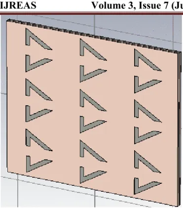
metamaterial Hexagona his design gi
Volum
onal Journal
power to R
f proposed m
design, sym ls is distribu ives the bett
me 3, Issue
l of Research http://www RMPA. The metamateria mmetrically uted equally ter improvem
e 7 (July 2
h in Enginee w.euroasiapu
maximum p
al structure
cut H and f y with each ment in impe
2013)
ering & App ub.org
power deliv
e at the heig
five hexagon h other and
edance bandw
ISSN
lied Science
ver to patch
ght of 3.2 m
nals are load cut horizont width and re
N: 2249-390
es
antenna is
mm from gro
ded on the p tally with 6 eduction in r
International Journal of Research in Engineering & Applied Sciences 7 http://www.euroasiapub.org
Figure 6. Rectangular microstrip patch antenna with proposed metamaterial structure.
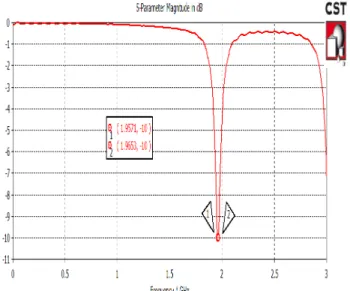
Simulation result of Return loss and bandwidth of Rectangular microstrip patch antenna loaded with metamaterial structure is shown in Fig 7.
IJREA
Figure 7 metemat
The Simu loss of -3 It is clear RMPA a Figure 8 Figure12 The max figure 12
S
Internati7. Simulatio terial struct
ulated result 30.1dB and B
r that the Dir lone.
8. Radiation
2. Delivered
imum powe 2.
Volum
onal Journal
on of Return ture at oper
t of RMPA lo Bandwidth o
rectivity of p
pattern of
d power to r
er deliver to
me 3, Issue
l of Research http://www
n loss and im rating frequ
oaded with h of 27 MHz.
proposed ant
proposed a
reduced size
o proposed
e 7 (July 2
h in Enginee w.euroasiapu
mpedance b uency 1.794
hexagonal sh
tenna is almo
antenna sho
e RMPA loa
rectangular
2013)
ering & App ub.org
bandwidth o GHz.
haped metam
ost unaffecte
owing Dire
aded with m
microstrip p
ISSN
lied Science
of RMPA wi
material is sh
ed in compa
ctivity of 6.
metamateria patch antenn
N: 2249-390
es ith propose howing returrison to simp
856 dBi.
al structure.
International Journal of Research in Engineering & Applied Sciences 9 http://www.euroasiapub.org
Figure13. E Field of the reduced size RMPA loaded with Metamaterial
Figure14. H Field of the reduced size RMPA loaded with Metamaterial.
IJREAS
Volume 3, Issue 7 (July 2013) ISSN: 2249-3905
International Journal of Research in Engineering & Applied Sciences 10 http://www.euroasiapub.org
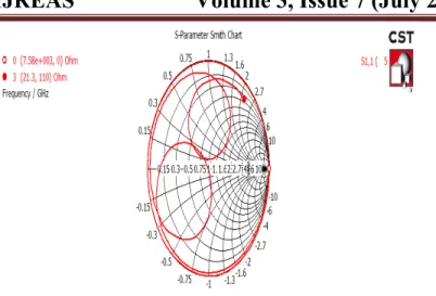
Figure 16. Smith chart of PMPA loaded with metamaterial.
The smith chart is very useful when solving transmission problems. The real utility of the Smith chart, it can be used to convert from reflection coefficients to normalized impedances (or admit-tances), and vice versa.
Smith chart of RMPA loaded with symmetrically cut H and hexagonal shaped metamaterial structure at 1.794 GHz. Above Fig. shows the impedance variation in the simulated frequency range and received impedance matching for proposed antenna at characteristic impedance.
IV. SIMULATION RESULTS
In this paper, Rectangular microstrip patch antenna loaded with symmetrically cut H and hexagonal shaped metamaterial structure is simulated using CST-MWS software. The pro-posed design in comparison to RMPA alone, found that the potential parameters of the propro-posed antenna is increased. This is clear from Fig.2 & Fig.7 that the return loss is reduced by 20.7 dB and bandwidth is increased by 16.7MHz. From the Fig.9, it is clear that the Directivity of pro-posed antenna design is almost unaffected. The maximum power deliver to propro-posed rectan-gular microstrip patch antenna is 1 watt.
V.
CONCLUSION
proper-International Journal of Research in Engineering & Applied Sciences 11 http://www.euroasiapub.org
ties of Metamaterial (MTM). By using Metamaterial, the maximum power delivered to proposed antenna is 1 watt as compared to the RMPA delivered power of 0.9 watt.
VI.
ACKNOWLEDGEMENT
The authors wish to thank their parents for their constant motivation without which this work would have never been completed. The authors are grateful to the Dr. Ghanshyam Singh,Director MPCT Gwalior for providing us lab facilities to complete this project work. We also express our gratitude towards Prof. Pankaj Shrivastava HOD Dept. of Elex. & comm. MPCT and Prof. Pan-kaj Singh Tomar,Asst. Professor Dept. of Elex. & Comm., MPCT for their continued support and guidance.
VII.
REFERENCES
1.H.A. Jang, D.O. Kim , and C. Y. Kim “ Size Reduction of Patch Antenna Array Us-ing CSRRs Loaded Ground Plane”Progress In Electromagnetics Research Sympo-sium Proceedings, KL MALAYSIA, March 27-30, 2012 1487.
2.Douglas, H. W., R. L. Haupt, and P. L. Werner, Fractal antenna engineering: The theory and design of fractal antenna arrays," IEEE Antennas and Propagation Magazine, Vol. 41, No. 5, 37-59, 1999.
3.Veselago, V. G., The electrodynamics of substances, with simultaneously negative values of and µ" Soviet Physics Uspekhi , Vol. 10, No. 4 , 509-514, 1968.
4.R.W. Ziolkowski, “Design fabricating and fabrication and testing of double negative me-tamaterials ,” IEEE Transactions on antennas and Propagation, vol.51, no.7, pp.1516-1529, July 2005.
5.Kuo, Y. L. and K. L. Wong, Printed double- T monopole antenna for 2.4/5.2 GHz dual-band WLAN operations," IEEE Trans. Antennas Propag., Vol. 51, No. 9, 2187-2192. 6. Constantine A. Balanis, Antenna Theory and Design, John Wiley & Sons, Inc., 1997. 7. L. Stutzman, G.A. Thiele, Antenna Theory and design , John Wiley & Sons 2nd Ed.,
New York,1998.