2016. ’. 47. ‚›. 6
STATUS OF THE MAJORANA DEMONSTRATOR
S. Vasilyev
1,∗, N. Abgrall
2, I. J. Arnquist
3,
F. T. Avignone III
4,5, C. X. Balderrot-Barrera
5, A. S. Barabash
6,
F. E. Bertrand
5, A. W. Bradley
2, V. Brudanin
1, M. Busch
7,8,
M. Buuck
9, D. Byram
10, A. S. Caldwell
11, Y.-D. Chan
2,
C. D. Christofferson
11, C. Cuesta
9, J. A. Detwiler
9,
Yu. Efremenko
12, H. Ejiri
13, S. R. Elliott
14, A. Galindo-Uribarri
5,
T. Gilliss
8,15, G. K. Giovanetti
8,15, J. Goett
14, M. P. Green
5,
J. Gruszko
9, I. Guinn
9, V. E. Guiseppe
4, R. Henning
8,15,
E. W. Hoppe
3, S. Howard
11, M. A. Howe
8,15, B. R. Jasinski
10,
K. E. Keeter
16, M. F. Kidd
17, S. I. Konovalov
6, R. T. Kouzes
3,
B. D. LaFerriere
3, J. Leon
9, J. MacMullin
8,15, R. D. Martin
10,
S. J. Meijer
8,15, S. Mertens
2, J. L. Orrell
3, C. O'Shaughnessy
8,15,
A. W. P. Poon
2, D. C. Radford
5, J. Rager
8,15, K. Rielage
14,
R. G. H. Robertson
9, E. Romero-Romero
12,5, B. Shanks
8,15,
M. Shirchenko
1, N. Snyder
10, A. M. Suriano
11, D. Tedeschi
4,
J. E. Trimble
8,15, R. L. Varner
5, K. Vetter
2, K. Vorren
8,15,
B. R. White
5, J. F. Wilkerson
5,8,15, C. Wiseman
4, W. Xu
14,
E. Yakushev
1, C.-H. Yu
5, V. Yumatov
6, I. Zhitnikov
1(The Majorana Collaboration)
1Joint Institute for Nuclear Research, Dubna
2Nuclear Science Division, Lawrence Berkeley National Laboratory, Berkeley, CA, USA
3Paciˇc Northwest National Laboratory, Richland, WA, USA
4Department of Physics and Astronomy, University of South Carolina, Columbia, SC, USA
5Oak Ridge National Laboratory, Oak Ridge, TN, USA
6Institute for Theoretical and Experimental Physics, Moscow
7Department of Physics, Duke University, Durham, NC, USA
8Triangle Universities Nuclear Laboratory, Durham, NC, USA
9Center for Experimental Nuclear Physics and Astrophysics and Department of Physics,
University of Washington, Seattle, WA, USA
10Department of Physics, University of South Dakota, Vermillion, SD, USA
11South Dakota School of Mines and Technology, Rapid City, SD, USA
12Department of Physics and Astronomy, University of Tennessee, Knoxville, TN, USA
13Research Center for Nuclear Physics and Department of Physics,
Osaka University, Ibaraki, Osaka, Japan
14Los Alamos National Laboratory, Los Alamos, NM, USA
15Department of Physics and Astronomy, University of North Carolina,
Chapel Hill, NC, USA
16Department of Physics, Black Hills State University, Spearˇsh, SD, USA
17Tennessee Tech University, Cookeville, TN, USA
The Majorana Collaboration is constructing the Majorana Demonstrator, an ultra-low background, 40-kg modular high purity Ge (HPGe) detector array to search for neutrinoless double-beta decay (0νββ decay) in76Ge. The goal of the experiment is to demonstrate a background rate at or below 3 counts/(t·y) in the 4 keV region of interest (ROI) around the 2039 keV Q-value for76Ge0νββ decay. In this paper, the status of the Majorana
Demonstrator, including its design and measurements of properties of the HPGe crystals, is presented.
PACS: 14.60.Pq; 23.40.-s; 29.40.-n
INTRODUCTION
Neutrinoless double-beta decay searches represent the only viable experimen-tal method to determine the DiracÄMajorana nature of the neutrino [1, 2]. The observation of this process would immediately imply that lepton number is vi-olated. Furthermore, the Majorana nature of the neutrino would allow for the see-saw mechanism [3, 4] to explain the, seemingly ˇnely tuned, small neutrino masses. Finally, the rate of0νββ decay could be used to determine the neutrino mass scale [5]. The0νββ-decay rate may be written as:
(T10/ν2)− 1
=G0ν|M0ν|2
mββ
me 2
, (1)
where G0ν is a phase space factor including the couplings, M0
ν is a nuclear
matrix element, me is the electron mass, and mββ is the effective Majorana
neutrino mass. The latter is given by
mββ=
3
i=0 Uei2mi
, (2)
where U2
ei speciˇes the admixture of neutrino mass eigenstate i in the electron
of light Majorana neutrinos, it is possible to establish an absolute scale for the neutrino mass, provided that nuclear matrix elements are known.
Experimentally, 0νββ decay can be detected by searching the spectrum of the summed energy of the emitted electrons for a monoenergetic line at the Q -value of the decay (Qββ). In previous-generation searches, the most sensitive
limits on 0νββ decay came from the HeidelbergÄMoscow experiment [6] and the IGEX experiment [7], both using76Ge. A direct observation of0νββ decay was claimed by a subgroup of the HeidelbergÄMoscow collaboration [8]. Recent sensitive searches for0νββhave been carried out in76Ge (GERDA [9]) and136Xe (KamLAND-Zen [10] and EXO-200 [11]), setting limits that do not support such a claim.
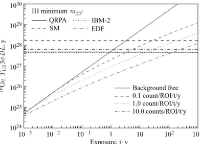
The sensitivity of a0νββ search increases with the exposure of the experi-ment, but ultimately depends on the achieved background level. This relationship is illustrated in Fig. 1, where the 3σ discovery level for the 76Ge 0νββ-decay half-life as a function of exposure in tonne-years for 4 different background lev-els is shown. The horizontal lines indicate the required half-life to reach the bottom of the inverted-hierarchy region (15 meV) for 4 different matrix element calculations andgA= 1.27. The detection efˇciency is taken to be 75%.
In order to reach the neutrino mass scale associated with the inverted mass hierarchy, 15Ä50 meV, a half-life sensitivity greater than 1027 y is required. This corresponds to a signal of a few counts or less per tonne-year in the 0νββ peak. Observation of such a small signal will require tonne-scale detectors with background contributions at or below a rate of 1 count/(ROI·t·y).
1030
1029
1028
1027
1026
1025
1024
10-3 10-2 10-1 1 10 102 103
Exposure, t y×
76Ge
TD
L
1/2
3y
s
,
IH minimummbb: QRPA SM
IBM-2 EDF
Background free 0.1 count/ROI/t/y 1.0 count/ROI/t/y 10.0 counts/ROI/t/y
Fig. 1. The 3σdiscovery level for the76Ge0νββ-decay half-life as a function of exposure
1. THE MAJORANA DEMONSTRATOR: OVERVIEW
The Majorana Demonstrator (MJD) [12] is an array of enriched and natural germanium detectors that will search for the 0νββ decay of 76Ge. The speciˇc goals of the MJD are:
• Demonstrate a path forward to achieving a background rate at or below 1 count/(ROI·t·y) in the 4 keV region of interest around the 2039 keVQββ of
the76Ge0νββ decay.
•Show technical and engineering scalability toward a tonne-scale instrument.
• Perform searches for other physics beyond the Standard Model, such as dark matter and axions.
To this end, the Collaboration is building the Demonstrator, a modular in-strument composed of two cryostats built from ultra-pure electroformed copper, each can house over 20 kg of HPGe detectors contained in an ultra-low back-ground structure that maximizes the concentration of crystals while minimizing the amounts of structural materials. Cryostats are mounted on moveable trans-porters allowing independent assembly and testing before installation into the shield. The array will contain 29 kg of detectors fabricated from 87% enriched 76
Ge and 15 kg of detectors from natural Ge (7.8%76Ge).
Starting from the innermost cavity, the cryostats will be surrounded by an inner layer of electroformed copper (5 cm), an outer layer of Oxygen-Free High thermal Conductivity (OFHC) copper (5 cm), high-purity lead (45 cm), an active muon veto (nearly 4π), borated polyethylene (5 cm), and polyethylene (25 cm) (see Fig. 2). The cryostats, copper, and lead shielding will all be enclosed in a radon exclusion box. The Rn enclosure is a gas tight barrier whose internal volume will be continuously purged with liquid nitrogen boil-off gas to reduce Rn levels near the cryostats. Inside the polyethylene shield two layers of active
Radon enclosure
Veto panels
Poly shield
Lead bricks Inner
Cu shield
Outer Cu shield
veto panels on all six sides of the apparatus will be installed. Veto panels are made out of 2.54 cm thick plastic scintillator and are read out by photo-multiplier tubes (PMTs). Detailed design of the veto panels is described in [13]. The entire experiment will be located in a clean room at the 4850 feet level of the Sanford Underground Research Facility (SURF) in Lead, South Dakota, USA [14].
An essential aspect of the Demonstrator is the production and use of ultra-clean Cu. In typical materials uranium and thorium decay-chain contaminants are found at levels of μg/g to ng/g, which would produce unacceptable back-ground in the Demonstrator. Electroforming copper in a carefully controlled and clean environment allows one to produce copper with U and Th below the level of 10−12 g/g [15]. The copper being produced by the Majorana Collaboration has about ten times lower U and Th impurities than commercial electroformed copper, with a projected level of 7.4·10−14 g/g for Th or lower. To avoid cosmogenic activation of the most sensitive parts, the copper is being produced at an underground (UG) production facility at SURF and at a shallow facility at Pa-ciˇc Northwest National Laboratory, and is being machined UG in an ultra-clean machine shop installed and operated by the Collaboration. Copper has mechan-ical, thermal, and electrical properties that are suitable for the Demonstrator's cryostats, detector mounts, and inner shield.
The Majorana Collaboration choose to use a modular approach to construct the experimental apparatus. Four or ˇve individual HPGe detectors and their
HV ring HV nut Hollow hex rod
Insulator
Mounting
plate ´4 or 5 ´7
Adaptor plate bolt
p-type point-contact detector
Natural of enriched p-type point-contact
detector unit assembly String assembly
Strings in module cryostat
associated low-mass low-radioactivity mounting structures and electronics are stacked together into one string assembly, and seven string assemblies are installed into one cryostat, as shown in Fig. 3.
2. STATUS OF THE MAJORANA DEMONSTRATOR
The construction of the Demonstrator is organized in three phases. In the ˇrst phase, a prototype cryostat made of commercial OFHC copper with three strings of natural HPGe detectors was constructed in 2013 and is taking data. The goal of this prototype is to demonstrate the integration of the various components (tors, vacuum, cooling, shielding, data acquisition). Most of the natural Ge detec-tors are the Broad Energy Ge detecdetec-tors (BEGe) manufactured by Canberra [16], and two natural Ge detectors are manufactured by AMETEK/ORTECR [17].
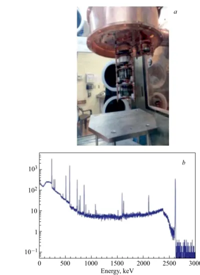
Ten natural HPGe detectors of both BEGe and ORTECR types are arranged into three strings and mounted under the cold plate inside the prototype module cryostat. DAQ systems based on the Object-Oriented Real-time Control and Ac-quisition (ORCA) platform [18] have been instrumented to control both commer-cial and collaboration-manufactured electronics. Using this system, background and calibration data are taken. The HPGe detectors in the prototype cryostat have shown good energy resolution similar to that in commercial cryostats. As an example, a spectrum taken by one of the HPGe detectors during a calibration run with a 228Th source is shown in Fig. 4. The Full Width at Half Maximum (FWHM) at 2615 keV is 3.2 keV.
The Demonstrator uses p-type point-contact (PPC) HPGe detectors [19, 20] that have masses in the range of 0.6Ä1.1 kg. PPC style detectors were chosen after extensive R&D by the Collaboration for their advantages: simple fabrication and very low capacitance, providing a low-energy threshold that allows the reduction of background from cosmogenically produced68Ge.
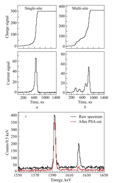
These detectors have all the beneˇts of coaxial HPGe detectors traditionally used for0νββ, but also possess superb pulse shape analysis (PSA) discrimination between single-site interactions (such as0νββ-decay events) and multi-site inter-action events (such as Compton scattering of γ-ray backgrounds), making them highly suitable for0νββ searches.
103
102
10
1
10-1
0 500 1000 1500 2000 2500 3000
Energy, keV
b a
Fig. 4.a) A photograph inside the prototype cryostat which is opened up to allow the mounting of three strings of HPGe detectors. b) A spectrum taken by one of the HPGe detectors in the prototype cryostat during a calibration run with a228Th source
300
200
100
0
Char
ge signal
Single-site 400 Multi-site
300
200
100
0
60
40
20
0
200 600 1000 1400
Current signal
Time, ns
a
200 600 1000 1400 Time, ns
b
80
60
40
20
0
400
350
300
250
200
150
100
50
0
1550 1570 1590 1610 1630 1650 Energy, keV
Counts/0.5 keV
Raw spectrum After PSA cut
c
Fig. 5.a) Charge and current pulse response of a PPC detector to single-siteγ-ray events.
b) Charge and current pulse response of a PPC detector to multi-siteγ-ray events. c) Pulse-shape analysis results for PPC data. The high spectrum is for all events within the energy range, while the low spectrum is for events that pass the PSA cut
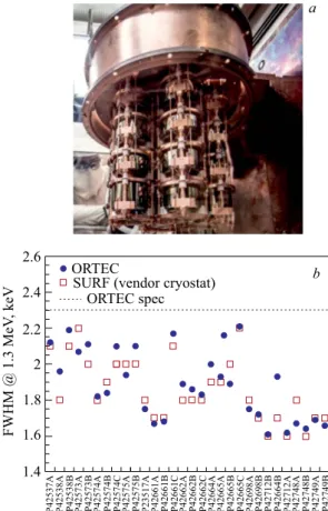
In the second phase, the ˇrst module made from electroformed copper has been populated with a mix of natural and enriched HPGe detectors (see Fig. 6) and will run inside the completed shield. All of the enriched Ge detectors are manufactured by AMETEK/ORTECR [17]. At the moment, ˇrst module is under commissioning.
Finally, in the third phase, a second cryostat made of electroformed copper and containing a mix of natural and enriched HPGe detectors will join the ˇrst module in the shield. At present, 25.2 kg of enriched germanium detectors are underground and Majorana is aiming for an additional≈4 kg of detectors from the recovery of scrap material. All enriched detectors are extensively tested and characterized in their vendor cryostat both at ORTECR and at SURF. The
a
2.6
2.4
2.2
2
1.8
1.6
1.4
ORTEC
SURF (vendor cryostat) ORTEC spec
FWHM @ 1.3 MeV
, keV
P42537A
b
P42538A P42538B P42573A P42573B P42574A P42574B P42574C P42575A P42575B P23517A P42661A P42661B P42661C P42662A P42662B P42662C P42664A P42665A P42665B P42665C P42698A P42698B P42712B P42664B P42712A P42748A P42748B P42749A P42749B
tests include measurements of the mass, impurity concentration, depletion and operating voltages, leakage current, energy resolution, electronic noise, dead layer, relative efˇciency compared to a 3×3-inch NaI(Tl) detector, and pulse-shape discrimination performance.
A number of measurements are performed with various sources placed 25 cm above the top surface of the cryostat. Data taken with60Co are used to determine the detector energy resolution at 1332.5 keV and the detection efˇciency relative to a3×3-inch NaI(Tl) detector. The FWHM of all detectors are better than the experimental speciˇcation of 2.3 keV, which is shown as the dotted horizontal line (see Fig. 6,b).
Prior to the ˇnal installation of the strings in the module cryostats, they are again tested in the String Test Cryostat (STC). The goal of these tests is to check the integrity of the detector, front-end electronics and HV connection after the re-installation of the detector in the Majorana mount.
CONCLUSIONS
The Collaboration has developed a number of techniques and materials in-cluding electroformed copper to achieve a projected background of < 3.1 counts/(ROI·t·y). A prototype module with three strings of natGe de-tectors was constructed in 2013 and has been in running since Summer of 2014. All enriched detectors met requirements during characterization in the vendor cryostat at ORTECR and SURF. The Majorana Demonstrator is commissioning the ˇrst module with 16.8 kg of enriched Ge detectors. Measurements in the STC showed positive results with respect to integrity and performance of the detectors in the Majorana mounts.
Acknowledgements. This material is based upon work supported by the U. S. Department of Energy, Ofˇce of Science, Ofˇce of Nuclear Physics. We acknowledge support from the Particle Astrophysics Program of the National Science Foundation. This research uses these US DOE Ofˇce of Science User Facilities: the National Energy Research Scientiˇc Computing Center and the Oak Ridge Leadership Computing Facility. We acknowledge support from the Russian Foundation for Basic Research. We thank our hosts and colleagues at the Sanford Underground Research Facility for their support.
REFERENCES
1. Camilleri L., Lisi E., Wilkerson J. F. Neutrino Masses and Mixings: Status and Prospects // Ann. Rev. Nucl. Part. Sci. 2008. V. 58. P. 343Ä369.
2. Avignone F. T. III, Elliott S. R., Engel J.Double Beta Decay, Majorana Neutrinos, and Neutrino Mass // Rev. Mod. Phys. 2008. V. 80. P. 481Ä516.
4. Mohapatra R. N., Senjanovic G. Neutrino Mass and Spontaneous Parity Violation // Phys. Rev. Lett. 1980. V. 44. P. 912Ä915.
5. Vergados J., Ejiri H., Simkovic F.Theory of Neutrinoless Double-Beta Decay // Rep. Prog. Phys. 2012. V. 75. P. 106301.
6. Baudis L. et al. (The HeidelbergÄMoscow Experiment). Limits on the Majorana Neu-trino Mass in the 0.1 eV Range // Phys. Rev. Lett. 1999. V. 83. P. 41Ä44.
7. Aalseth C. E. et al. (The IGEX Collab.).IGEX76Ge Neutrinoless Double-Beta Decay Experiment: Prospects for Next Generation Experiments // Phys. Rev. D. 2002. V. 65. P. 092007.
8. Klapdor-Kleingrothaus H. V., Krivosheina I. V.The Evidence for the Observation of 0Nu Beta Beta Decay: The Identiˇcation of 0Nu Beta Beta Events from the Full Spectra // Mod. Phys. Lett. A. 2006. V. 21. P. 1547Ä1566.
9. Agostini M. et al. (The GERDA Collab.). Results on Neutrinoless Double-β Decay of 76Ge from Phase I of the GERDA Experiment // Phys. Rev. Lett. 2013. V. 111. P. 122503.
10. Gando A. et al. (The KamLAND-Zen Experiment). Limit on Neutrinoless ββ Decay of 136Xe from the First Phase of KamLAND-Zen and Comparison with the Positive Claim in76Ge // Phys. Rev. Lett. 2013. V. 110. P. 062502.
11. Albert J. B. et al. (The EXO Collab.). Improved Measurement of the2νββ Half-Life of136Xe with the EXO-200 Detector // Phys. Rev. C. 2014. V. 89. P. 015502.
12. Abgrall N. et al. (The Majorana Collab.).The Majorana Demonstrator Neutrinoless Double-Beta Decay Experiment // Adv. High Energy Phys. 2014. V. 2014. P. 365432.
13. Bugg W., Efremenko Yu., Vasilyev S.Large Plastic Scintillator Panels with WLS Fiber Readout: Optimization of Components // Nucl. Instr. Meth. A. 2014. V. 758. P. 91Ä96.
14. Heise J.The Sanford Underground Research Facility at Homestake. arXiv:1503.01112v2 [physics-ins.det].
15. Hoppe E. W. et al. Microscopic Evaluation of Contaminants in Ultra-High Purity Copper // J. Radioanal. Nucl. Chem. 2009. V. 282. P. 315Ä320.
16. Meriden, Connecticut, USA: Canberra Industries, 2009.
17. Oak Ridge, Tennessee, USA: ORTEC, 2009.
18. Howe M. A. et al.Sudbury Neutrino Observatory Neutral Current Detector Acquisition Software Overview // IEEE Trans. Nucl. Sci. 2004. V. 51. P. 878Ä883.
19. Luke P. N. et al.Low Capacitance Large Volume Shaped-Field Germanium Detector // IEEE Trans. Nucl. Sci. 1989. V. 36. P. 926Ä930.
20. Barbeau P. S., Collar J. I., Tench O.Large-Mass Ultralow Noise Germanium Detectors: Performance and Applications in Neutrino and Astroparticle Physics // JCAP. 2007. V. 2007. 09. P. 9.