AIAA-02-4038
DESIGN, MANUFACTURING AND TEST
OF A PLUG NOZZLE ROCKET ENGINE
Eric Besnard*, Hsun Hu Chen†, Tom Mueller‡Mechanical and Aerospace Engineering Department California State University, Long Beach
John Garvey§
Garvey Spacecraft Corporation Huntington Beach, CA
* Lecturer, AIAA Member
†
Professor, AIAA Associate Fellow
‡
Independent Contractor, AIAA Member
§
President & CEO, AIAA Member
Copyright © 2002 by the American Institute of Aeronautics and Astronautics Inc. All rights reserved.
Abstract
The paper presents the design, manufacture and test of a small 1000 lbf ablative annular plug nozzle rocket engine. The engine was developed by students with the help from faculty and industry professionals as part of the California Launch Vehicle Education Initiative (CALVEIN). The design methodology is presented for the overall engine and its subsystems (injector, combustion chamber and plug nozzle). The flow over the plug nozzle is analyzed in more detail using Computational Fluid Dynamics (CFD) in conditions corresponding to a static fire test. Based on this analysis, the approximate design method used for determining the plug nozzle shape is shown to yield a highly efficient nozzle. The analysis also shows the importance of modeling flow property variations with temperature. The engine characteristics are discussed along with its manufacturing. The engine was tested and operated successfully for 200 ms after which the graphite plug failed. A different approach for securing the plug nozzle is under investigation and should lead to a new engine in the next few months. Finally, benefits of doing technology development and validation at such scales are presented. The example of CFD method validation for power-on in-flight flow conditions in subsonic, transonic and supersonic regimes is discussed.
1. Introduction
The concept of plug nozzles is not new. Research on the topic actively started in the 1950’s and lead to several static fire tests in the 1960’s [e.g. 1-6]. Their use was investigated for the Space Shuttle Main Engine (SSME) but the technology was deemed too risky at the time. More recently, during the 1990’s, NASA invested in the development of aerospike technology for Single-Stage-To-Orbit (SSTO) Reusable Launch Vehicles (RLV) as part of the now-defunct X-33 program. This program led to the development of several linear aerospike engines, RS 2200, which were tested repeatedly. To date, however, no aerospike engine is known to have powered a rocket in flight.
Unlike conventional bell-shaped nozzles, which operate optimally at one particular altitude, plug nozzles allow the flow expansion to self-adjust, thus improving thrust coefficients. This improvement over conventional bell-shaped nozzles occurs at altitudes lower than the design altitude. This is particularly critical for SSTO vehicles, which operate both in the atmosphere and in vacuum. At altitudes higher than the design altitude, plug nozzles essentially operate similarly to bell nozzles. For more details about the behavi or of the flow about plug nozzles, see for example Ref. 7. While the terms plug and spike nozzles are interchangeable, some authors associate aerospike nozzles with truncated spike nozzles with base bleed. In this paper, all three terms shall be used interchangeably.
The aerospike engine discussed here was developed as part of the California Launch Vehicle Education Initiative (CALVEIN), a collaborative program established at California State University, Long Beach (CSULB) in partnership with Garvey Spacecraft Corporation (GSC). One of the components of the program was the development of an aerospace system design curriculum. This curriculum takes the students through the product development cycle, from requirement definition to the actual manufacturing and test of an aerospace product, using a Systems Engineering approach in an integrated product team environment [8]. For the 2001-02 academic year, students took on the challenge of designing a small-scale annular ablative aerospike engine. Sect. 2 presents the methodology used by the students to design the engine and focuses on the flow characteristics over the plug nozzle. Sect. 3 outlines the engine manufacturing process and tests conducted.
Another objective of CALVEIN is to contribute to the development of technologies for low cost RLV’s. This can be accomplished in several forms, either by developing the technologies themselves, or by developing test platforms, which would be used –or easily modified– to perform low cost technology development and validation. One example would be to instrument such engine on board a low cost rocket, such as one of CSULB’s Prospector rockets [8], and launch it to experimentally characterize the effects of vehicle aerodynamics on aerospike engine performance. These are discussed at the end of the paper.
2. Design methodology and engine flow characteristics
2.1. From requirements to Preliminary Design Requirements
Within the framework of CALVEIN, students were required to design a 1000 lbf thrust annular ablative aerospike engine to be integrated to one of CSULB’s rockets, Prospector-2 or 3. The basic vehicle uses LOX and ethanol as propellants. The system is pressure-fed, with tank pressure set at 390 psi. Typically, the injector is designed for a pressure drop of around 90 psi in order to get a chamber pressure of 300 psi. Also, in order for the roughly 200 lb vehicle to clear the launch pad and gain an altitude of at least 4000 ft before parachute deployment, a burn time of at least 6 sec. was imposed. This project was built on the experience
gained by students in developing 1000 lbf thrust ablative engines using conventional bell-shaped nozzles [8].
Concept and overall engine sizing
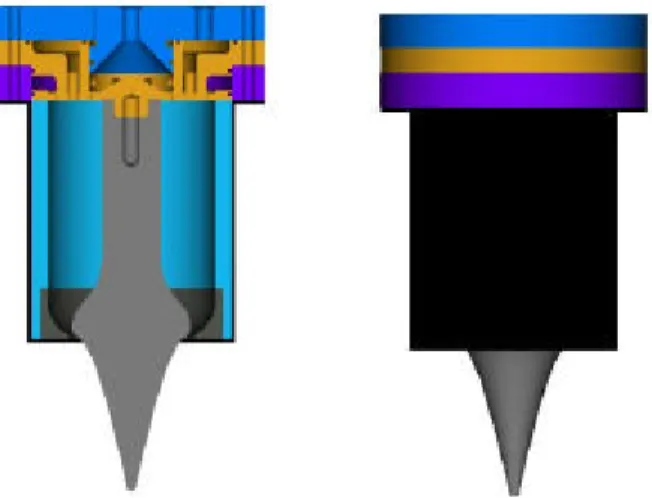
Several engine concepts were considered. Designs with fins to hold the plug in place were rejected because of the high temperatures that the fins would be subject to. The design evolved toward the concept of Fig. 1, in which the plug is held in place by a center rod mounted on the face of the injector. Also, because of the small scale of the engine, a single annular combustion chamber was chosen. Not shown is the ignition port which was a single small solid rocket motor providing a 3 second burn time.
Fig. 1. Solid model of the aerospike engine
From the requirements stated above and the selection of the design altitude (12,000 ft), the specific impulse, total mass flow rate, chamber volume, throat and exit areas are computed. For an ideal expansion at 12,000 ft, the area ratio is 5.12. For these calculations, a characteristics velocity (C*) efficiency of 90% and a chamber characteristic length (L*) of 50” can be assumed [9,10] so that the specific impulse (ISP) is approximately 235 s and the thrust coefficient would be CF = 1.495 (computed with TDK).
Based on these general characteristics of the engine, the next subsections address the design of the three main subsystems, injector, combustion chamber, and plug nozzle. The last subsection focuses on the flow predictions about the plug nozzle.
3
2.2. Injector and combustion chamber design Having determined the main engine characteristics, Fig. 2 shows the injector design process. After several trade studies, a series of 16 split triplets was selected because they allow positioning the liquid oxygen holes away from the chamber walls.
Also, the throat gap is only a few millimeters. Based on the data obtained from previously developed ablative engines with graphite nozzles without film cooling, it is necessary to add film cooling in order maintain this gap within reasonable limits (the design throat gap is approximately 4.5 mm). A film-cooling rate of 30% (alcohol) is provided by eight outer and eight inner holes. The number of holes and their size was determined as a compromise between performance and manufacturability in a typical university machine shop. Fig. 3 shows cross-sections of the injector. The ethanol manifolds are shown in red and the LOX manifolds are shown in blue.
Orifice Sizes Momentum Rate Ratio Weight Flow Rates Tank Press. (psi) Discharge Coefficient Mixture Ratio Injector Type Overall Injector Design Injector Layout
Fig. 2. Injector design process
Fuel holes LOX Holes Film Cooling Film Cooling
Fig. 3. Main injector plate cross-section
The combustion chamber was sized to ensure proper burning of LOX and ethanol. Like on previous engines, an ablative chamber was made (silica fibers and phenolic resin) with a steel outer shell.
2.3. Plug nozzle design
The contour of an aerospike nozzle can be designed by using either a simple approximate method [3,4] or Rao’s method based on calculus of variations [1]. The simple approximate method assumes a series of centered, isentropic expansion waves occur at the cowl lip of the aerospike nozzle. Using this method, the plug nozzle contour for a given expansion ratio, ε, and ratio of specific heats,
γ, can be determined. A brief description of this method is given below.
Since the flow is assumed to be parallel to the nozzle axis at the exit, the thruster angle is given by (Fig. 4a)
)
( e
t =νM
θ
where Me is the Mach number at the exit and the Prandtl-Meyer function, ν, is given by
1 tan ) 1 ( 1 1 tan 1 1 1 2− − 1 2− + γ − γ − γ + γ = ν − M − M
The throat area is
F c t t e t C p F r r A =π( 2− 2)/cosθ =
and the exit area of the aerospike is
) (e2 b2
e r r
A =π −
where re denotes the radius of the cowl lip, b
r denotes the base radius of the aerospike nozzle, pc the chamber pressure, F the thrust and CF the
thrust coefficient. Once the expansion ratio
t
e A
A
=
ε is given, re and rt can be determined for a fixed At.
The radial coordinate of the aerospike nozzle is given by t t t e e A A r r r r θ µ θ + µ − − = cos sin ) sin( ) ( 2 2 2 2
and the axial coordinate of the aerospike nozzle is given by ) tan(µ+θ − = r r x e
where θ=θt −ν and the Mach angle ) / 1 ( sin−1 M = µ .
The relationship between the Mach number and the area ratio is given by
) 1 ( 2 1 2 ) 2 1 1 ( 1 2 1 γ− + γ + γ− + γ = M M A A t
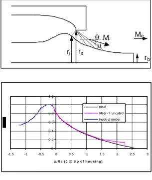
For the present engine, based on an ideal expansion at 12,000 ft and the throat area determined in Sect. 2.1, re =47.7mm. Fig. 4b
reasons, a non-zero base radius, rb, was selected
(13.5% of re, i.e. 6.44 mm). γ was assumed to be
constant at 1.21. The corresponding truncated plug nozzle is also shown in Fig. 4. For the current flow conditions, they differ very little. Also, the calculated plug length (approximately 2.3 re) is the same as the
one which can be determined from Rao’s method [1]. (a) re rt Me θ µM rb (b) 0 0.2 0.4 0.6 0.8 1 1.2 -1.5 -1 -0.5 0 0.5 1 1.5 2 2.5 3 x / R e ( 0 @ t i p o f h o u s i n g ) Ideal Ideal - Truncated Inside chamber
Fig. 4. (a) Notations for plug shape design method and (b) computed plug shapes.
2.4. Plug nozzle flow characteristics
One of the main issues associated with the use of plug nozzles in launch vehicles is the lack of validation of computational methods for predicting engine performance under a wide range of powered flight conditions, including speed and angle of attack. To the authors’ knowledge, published experimental data and corresponding Computational Fluid Dynamics (CFD) analyses are limited to static fire tests or to cold flow tests in wind tunnels and the like [11-13]. The problem is further complicated by the interest in bleeding propellants at the plug base in order to increase thrust [14]. For this case, very accurate solutions are required in order to determine optimum configurations with confidence.
As a first step toward power-on CFD validation, this section addresses the computation of the flow over the truncated plug nozzle designed in the previous section in static fire test conditions. The next step would be to perform similar computations at various flow conditions by varying altitude (or ambient pressure), Mach number and angle of
attack. Then, the rocket could be flown with some instrumentation to gather experimental data and compare with computations.
The Navier-Stokes solver selected for the present application is OVERFLOW [15] for it has the capability of computing flows with variable γ. The axisymmetric mesh was generated using ICEM-CFD [16], overlapped and then pre-processed with Pegasus [17]. The Spalart-Allmaras turbulence model was used in the computations. The inlet flow condition was specified inside the chamber by imposing total pressure and temperature, and extrapolating the mass flow rate for satisfying the sonic flow condition at the throat. This approach is necessitated by the fact that the sonic line at the throat is not straight and a-priori unknown due to the two-dimensional nature of the flow field.
Fig. 5 shows a comparison between computed density gradients employing the central difference and Roe schemes at design pressure/altitude, i.e. a pressure ratio (PR) of 32 for a constant γ (γ = 1.21). As expected, the latter is able to capture shocks when the former may not, particularly if these shocks are weak. Fig. 6 shows the base flow as computed with the Roe scheme.
Barrel Shock
Mach Disc Expansion Fan
Reflected Barrel Shock
Fig. 5. Schlieren-type plot at design pressure (PR=32) for the Roe scheme (top) and central difference
scheme (bottom) Isoline M=1 Streamline Dividing Streamline Stagnation Points
Fig. 6. Mach number and flow patterns near the plug base at design pressure
5
The thrust can be calculated by integrating the forces along the base and plug area, and by adding the momentum across the throat. The result is a thrust of 982 lbf or 4372 N, and a thrust coefficient of 1.472. With the definition of efficiency as
Fi F Fi C C C − − = η 1
where CFi is the ideal thrust coefficient and
neglecting the losses due to finite rate kinetics (not modeled in the CFD), the viscous and divergence losses can be computed. They are shown in Table 1 along with typical values for bell shaped nozzles representative of SSME performance [6]. As expected, at design pressure/altitude, there are virtually no divergence losses for the aerospike engine. Also, viscous losses are less for the annular aerospike engine because the nozzle area is less than for an equivalent bell shaped nozzle.
Efficiency Bell nozzle [6] Aerospike nozzle
Divergence 0.992 0.9995
Viscous 0.986 0.9947
Global 0.978 0.9942
Table 1. Comparison of bell and aerospike nozzle efficiencies
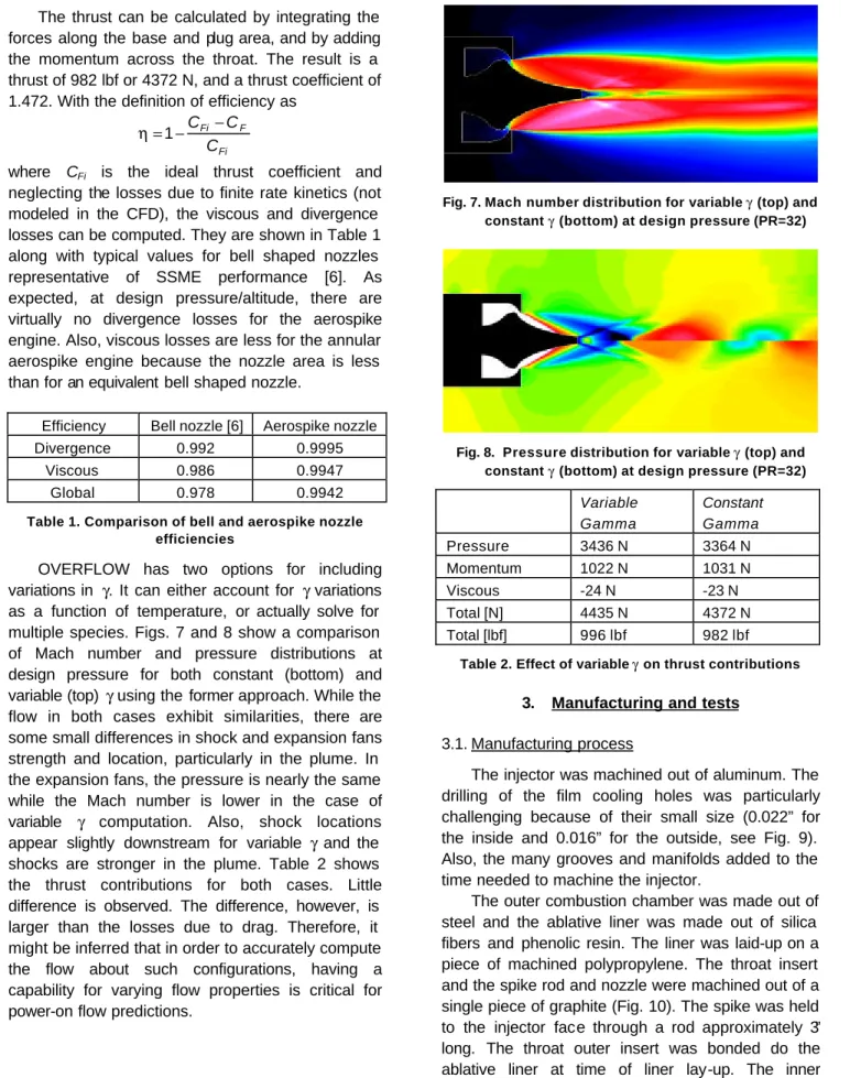
OVERFLOW has two options for including variations in γ. It can either account for γ variations as a function of temperature, or actually solve for multiple species. Figs. 7 and 8 show a comparison of Mach number and pressure distributions at design pressure for both constant (bottom) and variable (top) γ using the former approach. While the flow in both cases exhibit similarities, there are some small differences in shock and expansion fans strength and location, particularly in the plume. In the expansion fans, the pressure is nearly the same while the Mach number is lower in the case of variable γ computation. Also, shock locations appear slightly downstream for variable γ and the shocks are stronger in the plume. Table 2 shows the thrust contributions for both cases. Little difference is observed. The difference, however, is larger than the losses due to drag. Therefore, it might be inferred that in order to accurately compute the flow about such configurations, having a capability for varying flow properties is critical for power-on flow predictions.
Fig. 7. Mach number distribution for variable γ (top) and constant γ (bottom) at design pressure (PR=32)
Fig. 8. Pressure distribution for variable γ (top) and constant γ (bottom) at design pressure (PR=32)
Variable Gamma Constant Gamma Pressure 3436 N 3364 N Momentum 1022 N 1031 N Viscous -24 N -23 N Total [N] 4435 N 4372 N Total [lbf] 996 lbf 982 lbf
Table 2. Effect of variable γ on thrust contributions
3. Manufacturing and tests
3.1. Manufacturing process
The injector was machined out of aluminum. The drilling of the film cooling holes was particularly challenging because of their small size (0.022” for the inside and 0.016” for the outside, see Fig. 9). Also, the many grooves and manifolds added to the time needed to machine the injector.
The outer combustion chamber was made out of steel and the ablative liner was made out of silica fibers and phenolic resin. The liner was laid-up on a piece of machined polypropylene. The throat insert and the spike rod and nozzle were machined out of a single piece of graphite (Fig. 10). The spike was held to the injector face through a rod approximately 3” long. The throat outer insert was bonded do the ablative liner at time of liner lay-up. The inner combustion chamber is shown in Fig. 11 after
machining and before insertion into the steel outer chamber. Fig. 12 shows the fully integrated engine. Two ports are visible on the left, one for chamber pressure measurement and the larger one in the back for housing the solid motor used for engine ignition.
Fig. 9. Triplet injector with film cooling holes
Fig. 10. Machined graphite plug and throat insert
Fig. 11. Completed ablative liner and throat insert
Fig. 12. Fully integrated engine
3.2. Injector water-flow test
A water flow test was conducted to verify proper impingement of the various flows (Fig. 13), determine the actual pressure drop across the face of the injector, and trim the feed-lines if needed. The pressure drop was larger than anticipated (150 psi instead of 90 psi) on the fuel side because of the complex groove pattern inside the injector (the fuel enters the injector from the center and must also reach the outer rim of the injector). Trim orifices were added on the LOX side to obtain the proper mixture ratio.
Fig. 13. Water flow test of the injector
3.3. Static fire test and development status
The engine was integrated into the GSC-developed static fire test (SFT) stand, which includes a propulsion system and load cells for thrust
7
measurements. Fig. 14 shows the SFT stand fitted to VTS-2 at the Mojave Test Area (MTA), site owned and operated by the Reaction Research Society (RRS). Three load cells are located between two half-inch aluminum plates. Also, chamber pressure is measured by a pressure transducer mounted on the side of the chamber. Engine ignition is performed by lighting a small solid motor also mounted on the side of the chamber which provides approximately 3 seconds of burn.
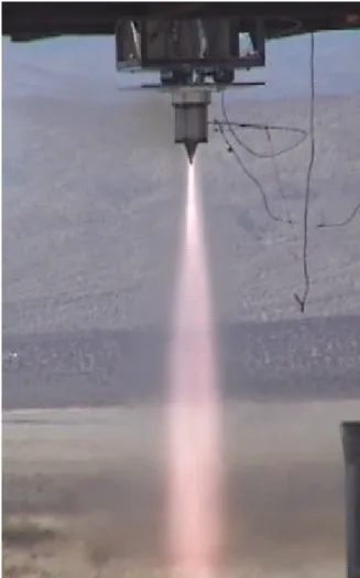
Fig. 15 shows the engine 200 ms after ignition in which a stable combustion is observed. Unfortunately, the spike failed structurally right after that, chocked the throat and lead to an explosion in the injector (Fig. 16). The failed bottom portion of the spike can be seen in the middle of Fig. 16 as it is being ejected away from the engine. The left over from the spike rod and where it failed are shown in Figs. 17 and 18, respectively. Unfortunately, because of too low a sampling rate, no useful data was recorded during the test.
Fig. 14. Aerospike engine on static fire test stand
Fig. 15. Aerospike engine 200 ms after ignition
Interestingly, the graphite did not break near the base of the injector where bending moments would have been larger nor near the end of the rod supporting the spike suggesting that bending was probably not the cause of failure. Instead, having used a very brittle material in tension sensitive to microcracks, without additional support through the entire length of the spike, was probably the cause of the failure. Analyses are currently being conducted to gain more information as to what changes to make in the next version of the engine. Various means of securing the plug nozzle for a several second burn are being investigated.
The test, however, validated the ignition sequence and, for a few ms, the soundness of the design. Students are already at work machining the next injector and preparing the next revised engine. A static fire test is planned for the Fall 02 and, if successful, will be followed by a launch of the previously-flown Prospector-2 vehicle.
Fig. 16. Explosion in injector right after spike failure
Fig. 17. Main injector plate and failed center rod
Plug failure location
Fig. 18. Location of spike failure
4. Conclusions
The paper presents the design, manufacture and test of a student-developed 1000 lbf thrust ablative annular aerospike engine. The overall engine design process is outlined. The design of engine subsystems is also presented. These include the injector, the combustion chamber and the plug nozzle. In order to assess the capability of existing CFD tools to compute the flow over aerospike nozzles under operating conditions, the flow over the plug nozzle is computed using the NASA-developed OVERFLOW code. Results show that variations in γ with temperature lead to small, albeit not null,
differences in thrust and plume characteristics. Also, the nozzle is shown to be highly efficient.
The engine was manufactured and tested. The static fire test was successful for 200 ms after which the engine spike nozzle structurally failed, resulting in an explosion of the engine. Students are now improving the baseline design to be able to test a new engine in a few months. The engine will then be static-fire tested and, if successful, the test will lead to the reuse of P-2 for the first flight of an aerospike engine in the history of rocket propulsion.
From an R&D perspective, beyond such milestone, the true benefit of developing the engine lies in the ability to instrument the flight vehicle to help characterize the aerospike performance and flow physics over spike nozzles over various flight regimes (speed and angles of incidence). In particular, if successfully developed, such platform could be modified to suit any desired aerodynamic shape and used to validate in-flight power-on CFD predictions. Such investigations could be performed at low cost and many scaled configurations could be tested at subsonic as well as supersonic speeds. As a step in this direction, research is being conducted to use CFD to characterize the slipstream effects on the annular aerospike engine performance when outfitted to the Prospector-2 rocket. These results could then be verified in flight with some sensors and, thus, contribute to paving the way toward the use of aerospike engines in tomorrow’s reusable launch vehicles.
Acknowledgements
The authors would like to acknowledge the California Technology Trade & Commerce Agency for partially funding CALVEIN. In addition, they would like to recognize the aerospike engine design student team, particularly Seth Quitoriano, Jeffrey Lang, Collin Corey and Brandy Irish.
References
1. G. V.R. Rao, “Spike Nozzle Contour for Optimum Thrust,” Ballistic Missile and Space Technology, Vol. 2, C.W. Morrow (Ed.), Pergamon Press, 1961.
2. K. Berman and F.W. Crimp Jr., “Performance of Plug-Type Rocket Exhaust Nozzles,” ARS J., Jan. 1961.
3. G. Angelino, “Approximate Method for Plug Nozzle Design,” AIAA J., Vol. 2, No. 10, 1964. 4. H. Greer, “Rapid Method for Plug Nozzle
9
5. R.P. Humphrey, H.D. Thompson and J.D. Hoffmann, “Design of Maximum Thrust Plug Nozzles for Fixed Inlet Geometry,” AIAA J., Vol. 9, No. 8, Aug. 1971.
6. R.A. O’Leary and J.E. Beck, “Nozzle Design”, Boeing Threshold Journal, Spring 1992. 7. J.H. Ruf and P.K. McConnaughey, “The Plume
Physics Behind Aerospike Nozzle Altitude Compensation and Slipstream Effect,” AIAA Paper No. 97-3217, 1997.
8. E. Besnard, J. Garvey, T. Holleman, T. Mueller, H.H. Chen and H.P. Chen, “Student
Development and Test of a Gimbaled Annular Aerospike Engine,” AIAA Paper No. 2002-4184, July 2002.
9. O. Biblarz and G. Sutton, Rocket Propulsion Elements, Wiley-Interscience, 7th Ed., Dec. 2000.
10. D. K. Huzel and D. H. Huang (Editors), Modern Engineering for Design of Liquid-Propellant Rocket Engines, Progress in Astronautics and Aeronautics, Vol. 147, AIAA, 1992.
11. E. Koutsavdis and G. Stuckert, “A Numerical Investigation of the Flow Characteristics of Plug Nozzles Using Fluent,” AIAA Paper No. 02-0511, Jan. 2002.
12. M. Onofri et al., “Plug Nozzles: Summary of Flow Features and Engine Performance,” AIAA Paper No. 02-0584, Jan. 2002.
13. R. Schwane, G. Hagemann and P. Reijasse, “Plug Nozzles: Assessment of Prediction Methods for Flow Features and Engine Performance,” AIAA Paper No. 02-0585, Jan. 2002.
14. T. Ito and K. Fuji, “Numerical Analysis of the Base Bleed Effect on the Aerospike Nozzles,” AIAA Paper No. 02-0512, Jan. 2002.
15. D. Jespersen, T. Pulliam and P. Buning, “Recent Enhancements to OVERFLOW,” AIAA Paper No. 97-0644, 1997.
16. ICEM-CFD Hexa, http://www.icemcfd.com, 2002
17. N. Suhs, S. Rogers and W. Dietz, “Pegasus 5: An Automated Pre-Processor for Overset-Grid CFD,” AIAA Paper No. 02-3186, June 2002.