Contents lists available atScienceDirect
Acta Astronautica
journal homepage:www.elsevier.com/locate/actaastro
The impact of methane oxidation kinetics on a rocket nozzle flow
Victor P. Zhukov
Institute of Space Propulsion, German Aerospace Center (DLR), Langer Grund, 74239, Hardthausen, Germany
A R T I C L E I N F O Keywords:
Methane rocket engine Methane kinetics Nozzle flow
Computational fluid dynamics Combustion modelling
A B S T R A C T
The impact of methane combustion kinetics on a rocket nozzle flow is theoretically studied in the work. To evaluate the effect of the kinetics, simulations of a rocket nozzle flow are carried out using the computational fluid dynamics solver Fluent. At first, a methane kinetic model is selected. The comparison of different kinetic models shows that the recent skeletal mechanism of Zhukov and Kong has a very good accuracy at a small size. For comparison, the flow simulations are performed both for hydrogen/oxygen and methane/oxygen propellant combinations, and for three different reaction models: non-reactive (“frozen”) flow, reactive (non-equilibrium) flow, and chemically equilibrium flow. Chemically non-equilibrium flow is modelled using the Zhukov–Kong model. Simulations results show that the recombination reactions of combustion products should be taken into account for modelling rocket nozzle flow. For hydrogen the difference in results between chemically non-equilibrium and non-equilibrium flows is negligible while in methane the difference is small but noticeable.
1. Introduction
Methane is the next generation rocket propellant [1]. The great interest in methane [2–7] stems from the possibility to build cost-ef-fective space transportation systems for a wide range of applications ranging from space tourism [7] to Mars missions [8,9]. The possibilities for the cost reduction offered by methane are due to its unique prop-erties: the high energy value at the low molecular weight of combustion products, the small difference in temperature and density between methane and oxygen in the liquid states, and the acceptable coolant performance at low thermal loads on the liner [1].
Nowadays, rocket engines are being designed with the use of CAD and CAE systems through the extensive use of numerical simulations. Modern numerical methods allow predictions about the characteristics of separate components and a whole rocket engine at design phase prior to manufacturing. Accurate numerical simulations significantly reduce development cost through reduction of the amount of required sub-scale, prototype, and test engines and their tests [10,11].
Hagemann et al. [12] carried out the numerical flowfield analysis of the Vulcan nozzle. They simulated H2/O2rocket nozzle flow using the
NASA TDK code [13]. The code includes both chemically equilibrium and chemical non-equilibrium models where “non-equilibrium” means finite-rate chemistry. Both models showed a good agreement with ex-perimental data. The comparison of the modelling results indicates that chemical kinetic effects have only minor influence on the rocket per-formance in high-pressure H2/O2rocket engines. The equilibrium and
non-equilibrium models predict practically the same temperature and
velocity profiles along the nozzle centreline. The difference between the models is only visible on mass fraction profiles along the centreline on a logarithmic scale; however, this difference does not exceed 10−3(i.e.,
0.1% in mass fractions).
In spite of extreme conditions in rocket engines, the reaction time between methane and oxygen cannot be considered as infinitely fast compared to other processes in many cases. These are flame near in-jector, gas generator and pre-burners, flows in a nozzle and near walls. Schumaker performed PLIF (planar laser-induced fluorescence) ob-servations of coaxial CH4/O2flames [14]. On the shots of the flame,
one clearly can see that the methane flame has a broken front meaning that the reaction time is larger than the mixing time in the shear layer. Gas generators and pre-burners in rocket engines operates at large excess of fuel or oxidizer so that the temperature of burnt gases rarely exceeds 900 K. Due to very low or high stoichiometric ratios (or, better to say, due to low flame temperature), gases sometimes leave gas generators and pre-burners partially unreacted. Betti et al. [15] studied the effect of chemical reactions on wall heat flux in methane and hydrogen rocket combustors. They found that for hydrogen the wall heat flux is the same both for the chemically equilibrium and chemically non-equilibrium flows. However, in the case of methane, the difference in wall heat flux between the non-reactive, the reactive (non-equilibrium), and the chemically equilibrium flows is noticeable, especially in the nozzle [15].
There are also other works where reactive nozzle flow was mod-elled, for example, [16–19]. However, these works are focused on technical aspects of the rocket nozzle modelling: reduction of
https://doi.org/10.1016/j.actaastro.2019.01.001
Received 7 September 2018; Received in revised form 17 December 2018; Accepted 3 January 2019 E-mail address:[email protected].
Available online 11 January 2019
0094-5765/ © 2019 The Author. Published by Elsevier Ltd on behalf of IAA. This is an open access article under the CC BY license (http://creativecommons.org/licenses/BY/4.0/).
computational time, nozzle design optimization, mesh convergence, etc. Thus, the role of kinetics in methane/oxygen nozzle flows has not been studied yet. While it was found that the relaxation to the equili-brium state is fast enough in H2/O2rocket nozzle flow, it is not yet clear
how fast the relaxation processes in methane combustion products, especially in the O2/CO/CO2 system, during expansion in nozzle.
Therefore, the aim of the present work: is to study the impact of che-mical kinetics on CH4/O2rocket nozzle flow.
The problem of reactive nozzle flow can be described as follows. In rocket engine, gas enters the nozzle well-mixed in the chemical equi-librium state at temperature of about 3500 K. During the expansion in a nozzle, the gas temperature decreases. This shifts the chemical equili-brium, and the gas relaxes to a new equilibrium state. The relaxation of gas in nozzle means the recombination of dissociated combustion pro-ducts and the release of the dissociation energy. The relaxation rate depends on density, and it decreases with the expansion of gases in nozzle. Thus, the flow monotonically accelerates in nozzle, but the re-laxation rate monotonically decreases. At one point, the rere-laxation time becomes of the same magnitude as the fluid-dynamic time scale. At this point, the kinetics of combustion products influences the flow. Further downstream, when the gas gets rarefied enough, the flow can be con-sidered as “frozen”. In H2/O2 mixtures the flow does not reach the
transition or “freezing” point, and the recombination of radicals is al-ways fast enough (at least in nozzles with an expansion nozzle ratio of about 50). Therefore, kinetic effects (the interaction between the hy-drodynamic and chemical timescales) do not influence H2/O2rocket
nozzle flow. The chemical kinetics and conditions of gas at the transi-tion and “freezing” points in CH4/O2rocket nozzle flow are a topic of
the present work.
2. Selection of kinetic model
When the reaction time scale is comparable with other time scales in rocket engine, it is necessary to take into account the methane kinetics and to use methane reaction mechanisms (where appropriate). Detailed hydrogen reaction mechanisms are used for CFD (Computational Fluid Dynamics) simulations of hydrogen rocket combustors and engines by many researchers; however, detailed methane mechanisms are sig-nificantly heavier and requires several times larger computational re-sources for CFD modelling than hydrogen mechanisms. Thus, there is a strong need for a “fast” light kinetic model for modelling methane oxidation in rocket engines.
Indeed, there is a method how to reduce detailed methane kinetic mechanisms approximately twice. After narrowing the range of appli-cation, a detailed kinetic mechanism becomes overdetermined and can be simplified to a skeletal mechanism by cutting off unnecessary species and reactions. This method of simplification has been used by many researches and is problem-oriented. It means that the mechanism ob-tained using this method, in some ways, is always “fitted” (or tuned) for a specific application. So, Petersen and Hanson developed the REDuced RAM accelerator mechanism (REDRAM) for reactive CH4/O2ram
ac-celerator flowfields [20]. (A ram accelerator is a device for accelerating projectiles using ramjet principles.) The mechanism was derived from the detailed methane mechanism (RAMEC—RAM accelerator ME-Chanism) from the same research group [21], which is in turn a slightly extended version of GRI-Mech 1.2 [22]. As it follows from its name, REDRAM is the problem-oriented model. The area of the application (ram accelerator) assumes high pressures (> 50 atm), low-dilution (mole fraction of inert component N2or Ar less than 70%), and fuel-rich
chemistry. This application assumes also ignition delay times and post-combustion temperatures as target parameters for modelling. The re-duction [20] was carried out through trial and error using the differ-ence in ignition delay times between the detailed (RAMEC) and reduced mechanisms as the selection criteria.
Another more sophisticated approach was used by Slavinskaya et al. [23]. As it follows from the title of their work “Methane Skeletal
Mechanism for Space Propulsion Applications”, it is supposed to be a desired model. However, it is not, although it is an important step in the right direction. The new skeletal mechanism is derived from the C1-C2 detailed mechanism of the same research group [24]. The simplification of the detailed mechanism was performed using an automated ap-proach. An in-house code runs a sensitivity analysis for reactions and species. After that, the code performs simulations of methane ignition and laminar flames and compares the results with experimental data. The procedure stops when the difference between simplified model and experiment reaches a prescribed value. The target function for the skeletal model was methane ignition delay data with a dilution of 75–98%, with stoichiometry of 0.5–2 at pressures of 0.5–175 atm and temperatures of 900–2200 K and laminar flame speeds of methane–air mixtures at ambient temperature in a pressure range of 0.5–60 atm. However, the conditions, at which the most of the experimental data were obtained, are far from the conditions in rocket engines. Three main distinctions of rocket engine conditions are the dilution level, which does not exceed 2%, pressure, which is far higher than 1 atm, and temperature, which reaches 3500 K in rocket combustion chambers. In work [21], Petersen et al. showed the importance of reactions with HO2, CH3O2, and H2O2 increases in the methane kinetics with the
transition to low dilution mixtures and high pressures.
In recent work [25], Zhukov and Kong presented a simplified me-thane reaction mechanism developed specifically for CFD simulations of methane rocket engines. They limited the domain of interest to un-diluted mixtures (i.e., only pure CH4/O2 mixtures) and to pressures
around 60 bar. The target function of the mechanism reduction was the accurate prediction of counterflow flame temperature at as much as possible compact mechanism. The new skeletal mechanism was derived from the detailed mechanism by Zhukov [26], or more precisely from its C1-C4 sub-mechanism [27]. The mechanism simplification was done in three stages. On the first stage, the reaction path analysis was carried out that allowed to cut off species, which have no influence on ignition and non-premixed flames of undiluted mixtures at high pressures. Then a sensitivity analysis was done which allowed identifying redundant reactions. On the third stage, the skeletal mechanism was further truncated manually, one reaction after another, until the difference with the parent detailed mechanism [27] in the predictions of coun-terflow flame temperatures reached 1%. Since there is no experimental data on flames and ignition delay times for undiluted methane mixtures at high pressures, the parent detailed mechanism [27] was taken as a reference. Thus, the new skeletal mechanism was compared by flame temperatures and ignition delay times in undiluted mixtures at high pressures not with experiments but with the detailed mechanism by Zhukov et al. [27]. The lack of comparison with experimental data under rocket engine-relevant conditions is the main drawback of all methane mechanisms.
There are also global and strongly reduced methane mechanisms. Two of them are widely used. The first is the quasi-global two-step mechanism of Westbrook and Dryer [28]. Another widely used me-chanism is the four-step meme-chanism of Jones and Lindstedt [29]. Both mechanisms were developed for the modelling of hydrocarbon–air flames at pressures around 1 atm; moreover, the Westbrook–Dryer mechanism is designed for premixed flames only. These mechanisms cannot be directly used for methane–oxygen mixtures because they do not take into account the dissociation of combustion products: water and carbon dioxide. Methane–oxygen flames have significantly higher temperature (than methane–air flames), at which it is necessary taking into account the dissociation of combustion products. At typical con-ditions for rocket combustion chambers (T=3600 K andp=60bar), the dissociation degrees of water and carbon dioxide amounts to 30% and 50%, respectively. To overcome this problem, Riedmann and Knab extended the Westbrook–Dryer mechanism [30], and Frassoldati et al. extended the Jones–Lindstedt mechanism [31]. Instead of the original versions of the mechanisms of Westbrook and Dryer and of Jones and Lindstedt, their extended versions will be always used further in the
text.
Comparison with experimental data (validation) is very important process for model development. It shows the accuracy and the range of validity of models. (Validity range shows at which parameters and boundary conditions a model can be employed.) Unfortunately, there is no experimental data on methane kinetics under rocket engine condi-tions. In this instance, the most relevant experimental data are the data obtained in methane–air or in similar mixtures at high pressures. In the present case, data on ignition delay times have been used for the vali-dation [32–36]. Ignition delay time can be considered as a character-istic reaction time between methane and oxidizer, in our case air or similar mixture of oxygen with N2, Ar or He as dilutant. Ignition delay
times for methane depend on conditions: temperature, pressure, equivalence ratioϕ, heat capacity of neutral dilutant, etc.
In the present report, all simulations of ignition have been per-formed using Cantera at conditions of a constant-volume adiabatic batch reactor. Cantera is an open-source software package for solving chemical kinetic and thermodynamic equations [37]. It allows model-ling of different types of chemical reactors in 0D and 1D problem for-mulations.
The comparisons of different methane kinetic models have been performed against experimental data on ignition delay times for 13 different data sets [32–36]. These data cover a wide range of para-meters; the information about the validation range can be found in Table 1. The results of the calculations are compiled inTable 2. Two typical cases are shown on Figs. 1 and 2; in the other eleven cases, results are similar.
The skeletal model of Zhukov and Kong was also compared with the detailed Zhukov C1-C4 model under rocket engine conditions (pure CH4/O2mixture at 60 bar) in original work [25]. For the comparison,
the ignition of CH4/O2mixture in a constant pressure adiabatic reactor
and a non-premixed counterflow CH4/O2flame were simulated. The
comparison showed a negligible difference between the skeletal and detailed models at these conditions. The difference in flame tempera-ture between the skeletal Zhukov–Kong model [25] and the detailed Zhukov C1-C4 model [26] amounted to 0.5–1%. The size of kinetic mechanism (i.e., the amount of species and reactions) is no less im-portant for Computational Fluid Dynamics (CFD) modelling than ac-curacy. Each additional species in the mechanism results in an addi-tional transport equation in the CFD model. Taking into account that the skeletal Zhukov–Kong model has the same accuracy in pure CH4/O2
mixtures at high pressures as the detailed Zhukov C1-C4 and RAMEC models, it is preferable to use the Zhukov–Kong model for CFD simu-lations of methane rocket engines. The Zhukov–Kong model is compact and consists of 23 species and 51 reactions, while the detailed me-chanisms are significantly larger—RAMEC: 38 species and 199 reac-tions; the most used GRI-Mech 3.0 [38]: 53 species and 325 reactions. As regards another skeletal mechanism, REDRAM, which also shows good accuracy in the prediction of the ignition delay times, it was shown in work [25] that it is not able predict the temperature of me-thane–oxygen flames. It predicts the flame temperature below 3000 K, which is unacceptably low.
3. CFD modelling
In order to study the impact of reaction kinetics on CH4/O2rocket
nozzle flow, CFD simulations have been carried out using the commercial CFD solver ANSYS Fluent. To model the nozzle flow, the compressible Euler equations have been solved in a two-dimensional axisymmetric problem formulation using the implicit density-based solver and the second-order upwind scheme. The geometry of the numerical domain and the numerical grid are presented in Fig. 3. Table 1
Parameter range of the validation data set.
Parameter Range
Pressure: 15–450 atm
Temperature: 870–1600 K
Equivalence ratioϕ: 0.4–6
Dilutant: air, N2, Ar, He
Dilutant vol. fraction: 33–76%
References: [32–36]
Table 2
Mean absolute percentage error for different kinetic mechanisms. Mechanism Errorafor data
(Zhukov, 2003) Error afor data
(Huang, 2004) Average for 13different data sets [32–36] Zhukov C1-C4 [26] 18% 18% 22% Zhukov–Kong [25] 21% 36% 23% RAMEC [21] 20% 35% 22% REDRAM [20] 14% 28% 24% Slavinskaya et al. [23] 180% 178% 85% Westbrook–Dryerb,[30] 84% 86% 92% Jones–Lindstedtb,[31] > 300% > 300% > 300% GRI-Mech 3.0 [38] 20% 80% 93% a Err.= n exp sim exp 1 .
b The original mechanisms overpredict significantly the temperature of
me-thane–oxygen flames; thus, their modified versions are used here.
Fig. 1.Comparison of different models with experimental data [32]: metha-ne–air, =0.5, 150 atm.
Fig. 2.Comparison of different models with experimental data [33]: metha-ne–air, =1.3, 40 atm.
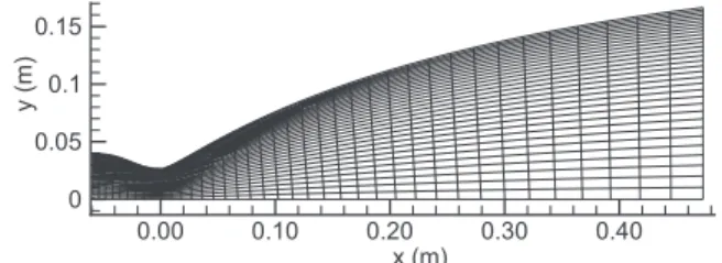
The contour of the nozzle replicates the nozzle geometry of project LUMEN [39]. The structured two-dimensional (2D) numerical grid consists of128×153(y×x) nodes. It is relatively uniform and slightly refined near the wall. The inlet (left) is a pressure inlet with a pressure set to 60 bar. At the outlet (right), the supersonic boundary conditions are set. The throat diameter equals to 26.375 mm.
The chemical equilibrium mixture of burnt gases enters inside the nozzle at the inlet. The temperature and mixture composition at the inlet were calculated for the CH4/O2mixture with ROF (oxidizer to fuel
ratio) of 3.4 using NASA CEA code [40]. The simulations have been performed for three cases:
a) chemically non-reactive “frozen” flow: mixture composition is con-stant after the cylindrical section of the combustion chamber. b) chemical non-equilibrium flow: species react with a finite rate in
accordance with the Zhukov–Kong kinetic model.
c) chemical equilibrium flow: mixture composition get instantly changed to a new equilibrium when temperature or pressure get changed.
For comparison, H2/O2 nozzle flow with ROF = 6 has also been
simulated.
The used numerical model disregards gas viscosity, turbulence and radiative heat transfer. Flow in rocket engine nozzles can be assumed to be inviscid [41]. Therefore, this simple problem formulation provides adequate and required boundary conditions for solving the kinetic equations and thus makes possible to estimate the effect of reaction kinetics on the nozzle flow.
4. Results and discussion
The results of the nozzle flow simulations are presented in figures below. For comparison, the results both for hydrogen and methane are shown. First, the temperature field in the nozzle is shown and then follows graphs of the temperature and velocity on the nozzle centreline. InFigs. 4 and 5, the temperature fields in the nozzle are shown for the both hydrogen and methane cases. The figures give a general idea about the flow in the nozzle. The hot gases (red colour in the figure) enter into the nozzle where they accelerate, expand, and cool down (get blue colour in the figure) as they move downstream. The used numer-ical model does not take into account turbulence and heat transfer; therefore, it cannot model processes on wall: heat transfer, flow se-paration, etc. However, the model can adequately reproduce the con-ditions on the nozzle axis.
The temperature of the gases on the centreline is shown inFig. 6. The simulations of the H2/O2rocket nozzle flow reproduce the results
obtained earlier by Hagemann et al. [12] and by other researches [15]. In the case of hydrogen, the difference between the equilibrium and non-equilibrium models is negligible (insignificant). In the case of methane, the difference between the equilibrium and non-equilibrium models is noticeable and appears relatively early, at a distance of three throat diameters from the nozzle throat, at temperature of about 2800 K. The difference between hydrogen and methane originates from the slow kinetics in the pair of CO and CO2 while the kinetics of
dissociated water vapour is significantly faster. The reaction rate con-stants for the recombination of CO into CO2 and for the equivalent
reaction of H2O are plotted for the considered temperature range in
Fig. 7. The reaction rate constant of reaction
+ + +
O CO M CO2 M
is an order of magnitude less than the reaction rate constant of reaction
+ + +
H OH M H O M.2
Moreover, the reaction rate constant of recombination of O and CO is getting smaller when the temperature drops in flow, while for the H2/
O2nozzle flow the reaction rate constant becomes only larger. (The
equilibrium chemistry model assumes in turn infinite rates of reac-tions.)
As for the chemically frozen flow, it has a lower temperature since there is no recombination of the dissociated gases and there is no ad-ditional heat release. This was already seen by Zhukov and Suslov [42]. They simulated a sub-scale rocket combustor fuelled by cryogenic hy-drogen and oxygen. The thrust chamber assembly also included a short nozzle. The turbulent combustion was modelled by two different models: the extended eddy-dissipation model and a flamelet-based model. The flamelet approach assumes no further chemical reaction behind a flame front, which means the chemically frozen flow also in the nozzle. The comparison of the models showed that the assumption of chemically frozen flow leads to the lower temperature in nozzles and consequently to the lower pressure in combustion chambers.
Fig. 3.Numerical domain and grid (in the figure, the grid has been coarsened by a factor of four in each direction for a better visualization).
Fig. 4.Temperature field in the nozzle: H2/O2, ROF = 6,pc= 60 bar; equili-brium flow (top), non-equiliequili-brium flow (bottom).
Fig. 5.Temperature field in the nozzle: CH4/O2, ROF = 3.4, pc= 60 bar; equilibrium flow (top), non-equilibrium flow (bottom).
InFig. 6, the difference between the “frozen” and non-equilibrium flows monotonically grows, which means that the chemical kinetics has an impact on the flow over the whole length of the nozzle. In other words, the flow cannot be considered as “frozen” (at least in the con-sidered nozzle) even close to the nozzle exit. The impact of the kinetics
is very well demonstrated a plot inFig. 8, where evolutions of main mixture components along the nozzle axis is shown. The “frozen” flow is not shown because it simply means horizontal lines on the plot. The equilibrium model is shown by points. The OH mass fraction for the equilibrium flow is not shown on the plot because the difference with the non-equilibrium flow is too small on a linear scale; however, the difference between the three flows is the most noticeable primarily for radicals. For instance, the amounts exactly of OH at the nozzle exit for the different reaction models refer to each other as “frozen”/non-equilibrium/equilibrium = 1/0.1/0.002. The linear scale is chosen in order to show the main effect of the recombination, namely the increase of the fractions of H2O and CO2. The mass fraction of CO2
mono-tonically grows along the axis from 0.25 to 0.40. The sum mass fraction of H2O and CO2grows from 0.66 to 0.83. The growth occurs due to the
further oxidation of CO and due to the recombination of radicals. The total mass fraction of radicals OH, O, and H decreases from the nozzle inlet to the nozzle exit from 6.3% to 0.8%. The values are given for the non-equilibrium flow. The difference between the non-equilibrium and equilibrium flows for H2O and CO2amounts 3%. It becomes visible
after three throat diameters. The recombination into H2O goes faster
than into CO2in the both models, which is not surprising.
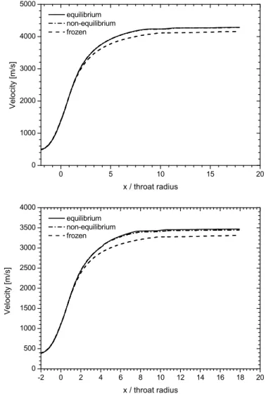
For design of rocket engines, the temperature of gases on the cen-treline is not as important as performance parameters of rocket engine: thrust and specific impulseIsp. They both are proportional to exit ve-locity. The velocity on the nozzle axis is shown inFig. 9. The difference in the velocity for the equilibrium and non-equilibrium models is negligible for hydrogen. The lines corresponded to these models coin-cide with each other. This result was already shown for hydrogen by Hagemann et al. [12]. In CH4/O2nozzle flow, the lines are very close to
each other; the difference between the equilibrium and non-equilibrium models is slightly less than 1%. In the present case, the equilibrium model yelds an additional 1% toIsp. The model of “frozen” flow predicts essentially lower velocities in both cases: H2/O2and CH4/O2. In the
present case, it underestimates the value ofIsp for methane by 6.6%. The CFD simulations shows that the short nozzles with low expansion ratio can be modelled using the assumption of the chemical equilibrium both for H2/O2and CH4/O2flows. However, accurate simulations of
CH4/O2nozzle flow require taking into account the reaction kinetics of
dissociated combustion products especially if the nozzle has a large expansion ratio or gas temperature drops below 2800 K.
Fig. 6.Temperature of the gases on the centreline: H2/O2 (top), CH4/O2
(bottom).
Fig. 7.Reaction rate constants for the recombination into H2O and CO2
(en-hanced third body efficiency multiplier is not applied) [25].
Fig. 8.Evolutions of main mixture components on the nozzle axis: CH4/O2,
5. Conclusions
The literature study has shown a potential impact of chemical ki-netics on rocket nozzle flows in CH4/O2mixtures. To study the effect of
reaction kinetics, CFD simulations of nozzle flow have been carried out. First, however, a methane kinetic mechanism was selected for CFD modelling from eight different kinetic mechanisms. The selection cri-teria were the accuracy of mechanism in ignition delay times at high pressures and the amount of species and reactions in mechanism. The skeletal mechanism of Zhukov and Kong consisting of 23 species and 51 reactions showed a very good agreement with experimental data, and it was selected for the following CFD simulations.
The CFD simulations were carried out using the commercial CFD solver ANSYS Fluent and the nozzle geometry of the project LUMEN. To speed up the modelling, the used numerical model disregards gas viscosity, turbulence, radiative heat transfer, and the formation of boundary layers; however, it appropriately models the acceleration and expansion of gases near nozzle centreline. The CFD simulations of the nozzle flow have been performed using three different reaction models: “frozen” flow, non-equilibrium flow (using the Zhukov–Kong kinetic model), and chemically equilibrium flow. For comparison, the CFD si-mulations have been carried both for H2/O2and CH4/O2flows under
similar conditions.
The comparison of the results of the CFD simulations shows that the assumption of “frozen” flow gives in inaccurate results: temperature and velocity of the flow are too low, and there is no conversion of CO into CO2 during the flow in the nozzle. The assumption of reactive
nozzle flow (chemically non-equilibrium or equilibrium) allows taking into account the additional heat release during the recombination of dissociated combustion products. For hydrogen, the difference between non-equilibrium or equilibrium flows is insignificant in nozzle. For methane, the difference between non-equilibrium or equilibrium flows becomes visible when the temperature of the flow drops below 2800 K (for the used nozzle contour at a distance of 2–3 throat diameters from the nozzle throat). The difference between hydrogen and methane re-sults from the slow rate of the recombination of CO into CO2, which
decreases at low temperature. The assumption of chemically equili-brium flow results in higher exit velocity; however, the overshoot is slightly less than 1% and insignificant.
The reaction kinetics manifests itself in the increase of the mass fractions of H2O and CO2along the nozzle axis, in the monotonous
conversion of CO into CO2, and in the recombination of radicals. The
total mass fraction of radicals decreases in the present case from 6.3% at the nozzle inlet to 0.8% the nozzle exit. The difference between the three reaction models is the most noticeable in radicals. For example, the amounts of OH at the nozzle exit for the reaction models refer to each other as “frozen”/non-equilibrium/equilibrium = 1/0.1/0.002. The difference between the non-equilibrium and equilibrium flows in the main mixture components (H2O and CO2) is not large and amounts
to 3%.
The present paper has clearly shown that accurate simulations of hot nozzle flows require taking into account recombination reactions, especially their heats of reaction, in hot combustion products.
Acknowledgements
The present work was conducted in the frameworks of the German Aerospace Center (DLR) projects Future Fuels and LUMEN (Liquid Upper Stage deMonstrator ENgine). The work was presented at the 6th Conference on Space Propulsion in Seville, Spain, 14–18 May 2018.
References
[1] G. Hagemann, M. Onofri, S. Schlechtriem, F. Wilson, M. Rudnych, Plenary round table: LOX Methane, Space Propulsion, 2016 Rome, 2016.
[2] F. Battista, D. Ricci, D. Cardillo, P. Natale, M. Fragiacomo, M. Ferraiuolo, V. Salvatore, The HYPROB LOX-LCH4demonstrator: status of the manufacturing
and experimental activities, Proceedings of the 7th European Conference for Aeronautics and Space Sciences, 2017,https://doi.org/10.13009/eucass2017-360. [3] R.H. Dos Santos Hahn, G. Waxenegger, J. Deeken, M. Oschwald, S. Schlechtriem,
Utilization of LOx/LCH4expander-bleed cycles for upper stage engine applications,
Proceedings of the 7th European Conference for Aeronautics and Space Sciences, 2017,https://doi.org/10.13009/eucass2017-370.
[4] D. Liuzzi, M. Rudnykh, D. Drigo, N. Ierardo, Architecture trade-off for the VEGA-E upper stage LOX/CH4engine, Proceedings of the 7th European Conference for
Aeronautics and Space Sciences, 2017,https://doi.org/10.13009/eucass2017-484. [5] A. Deneuve, E. Humbert, L. Lesaunier, S. Dreyer, V. Leudiere, J. Herpe, M. Theron, A. Du Tertre, D. Guichard, BOREAS demonstrator for future liquid propulsion en-gines, Proceedings of the 7th European Conference for Aeronautics and Space Sciences, 2017,https://doi.org/10.13009/eucass2017-503.
[6] A. Iannetti, Prometheus, a LOX/LCH4reusable rocket engine, Proceedings of the 7th
European Conference for Aeronautics and Space Sciences, 2017,https://doi.org/10. 13009/eucass2017-537.
[7] J.-P. Dutheil, Y. Boue, Highly reusable LOx/LCH4ACE rocket engine designed for
SpacePlane: technical maturation progress via key system demonstrators results, Proceedings of the 7th European Conference for Aeronautics and Space Sciences, 2017,https://doi.org/10.13009/eucass2017-552.
[8] K.R. Sridhar, Mars sample return mission with in-situ resource utilization, J. Propul. Power 11 (6) (1995) 1356–1362,https://doi.org/10.2514/3.23979.
[9] S. Green, D. Deffenbaugh, M. Miller, A comparison of five ISPP systems for a Mars sample return mission, 35th Joint Propulsion Conference and Exhibit, 1999, p. 2410, ,https://doi.org/10.2514/6.1999-2410.
[10] O. Knab, M. Frey, J. Grgen, K. Quering, D. Wiedmann, C. Mding, Progress in combustion and heat transfer modelling in rocket thrust chamber applied en-gineering, 45th AIAA/ASME/SAE/ASEE Joint Propulsion Conference & Exhibit, Joint Propulsion Conferences, American Institute of Aeronautics and Astronautics, 2009, ,https://doi.org/10.2514/6.2009-5477.
[11] O. Knab, H. Riedmann, B. Ivancic, C. Hglauer, M. Frey, T. Aichner, Consequences of modeling demands on numerical rocket thrust chamber flow simulation tools, 6th European Conference for Aeronautics and Space Sciences, EUCASS), 2015paper id: 404.
[12] G. Hagemann, G. Kruelle, K. Hannemann, Numerical flowfield analysis of the next Fig. 9.Velocity of the gases on the centreline: H2/O2(top), CH4/O2(bottom).
generation Vulcan nozzle, J. Propul. Power 12 (4) (1996) 655–661,https://doi.org/ 10.2514/3.24086.
[13] G. Nickerson, L. Dang, D. Coats, Two dimensional reference computer program, Tech. Rep. NAS (1985) 8-35931, Huntsville, AL.
[14] S.A. Schumaker, An Experimental Investigation of Reacting and Nonreacting Coaxial Jet Mixing in a Laboratory Rocket Engine, Ph.D. thesis University of Michigan, USA, 2009.
[15] B. Betti, D. Bianchi, F. Nasuti, E. Martelli, Chemical reaction effects on heat loads of CH4/O2and H2/O2rockets, AIAA J. 54 (1) (2016) 1693–1703,
https://doi.org/10.2514/1.J054606.
[16] G. Cai, J. Fang, X. Xu, M. Liu, Performance prediction and optimization for liquid rocket engine nozzle, Aero. Sci. Technol. 11 (2–3) (2007) 155–162,https://doi.org/ 10.1016/j.ast.2006.07.002.
[17] L.K. Araki, C.H. Marchi, Verification of numerical solutions for reactive flows in a regeneratively cooled nozzle, J. Braz. Soc. Mech. Sci. 32 (3) (2010) 267–275, https://doi.org/10.1590/S1678-58782010000300010.
[18] D. Schneider, C. Génin, R. Stark, M. Oschwald, S. Karl, V. Hannemann, Numerical model for nozzle flow application under liquid oxygen/methane hot-flow condi-tions, J. Propul. Power 34 (1) (2017) 221–233,https://doi.org/10.2514/1.B36611. [19] M. Yumuşak, S. Eyi, Design optimization of rocket nozzles in chemically reacting
flows, Comput. Fluids 65 (2012) 25–34,https://doi.org/10.1016/j.compfluid.2012. 05.002.
[20] E.L. Petersen, R.K. Hanson, Reduced kinetics mechanisms for ram accelerator combustion, J. Propul. Power 15 (4) (1999) 591–600,https://doi.org/10.2514/2. 5468.
[21] E. Petersen, D. Davidson, R. Hanson, Kinetics modeling of shock-induced ignition in low-dilution CH4/O2mixtures at high pressures and intermediate temperatures,
Combust. Flame 117 (1) (1999) 272–290, https://doi.org/10.1016/S0010-2180(98)00111-4.
[22] M. Frenklach, H. Wang, M. Goldenberg, G. Smith, D. Golden, C. Bowman, R. Hanson, W. Gardiner, V. Lissianski, GRI-Mech—an optimized detailed chemical reaction mechanism for methane combustion, Tech. Rep. GRI-95/0058, Gas Research Institute, Nov. 1995.
[23] N.A. Slavinskaya, A. Meddi, J.-H. Starcke, O.J. Haidn, Methane skeletal mechanism for space propulsion applications, 52nd AIAA/SAE/ASEE Joint Propulsion Conference, AIAA Propulsion and Energy Forum, AIAA, 2016, pp. 2016–4781 https://doi.org/10.2514/6.2016-4781.
[24] N.A. Slavinskaya, U. Riedel, S.B. Dworkin, M.J. Thomson, Detailed numerical modeling of PAH formation and growth in non-premixed ethylene and ethane flames, Combust. Flame 159 (3) (2012) 979–995,https://doi.org/10.1016/j. combustflame.2011.10.005.
[25] V.P. Zhukov, A.F. Kong, A compact reaction mechanism of methane oxidation at high pressures, Prog. React. Kinet. Mech. 43 (1) (2018) 62–78,https://doi.org/10. 3184/146867818X15066862094914.
[26] V.P. Zhukov, V.A. Sechenov, A.Y. Starikovskii, Autoignition of a lean propane–air mixture at high pressures, Kinet. Catal. 46 (3) (2005) 319–327,https://doi.org/10. 1007/s10975-005-0079-7.
[27] V.P. Zhukov, Kinetic model of alkane oxidation at high pressure from methane to n-heptane, Combust. Theor. Model. 13 (3) (2009) 427–442,https://doi.org/10.1080/
13647830902767302.
[28] C.K. Westbrook, F.L. Dryer, Simplified reaction mechanisms for the oxidation of hydrocarbon fuels in flames, Combust. Sci. Technol. 27 (1–2) (1981) 31–43, https://doi.org/10.1080/00102208108946970.
[29] W.P. Jones, R.P. Lindstedt, Global reaction schemes for hydrocarbon combustion, Combust. Flame 73 (3) (1988) 233–249,https://doi.org/10.1016/0010-2180(88) 90021-1.
[30] H. Riedmann, O. Knab, Two-dimensional and three-dimensional RANS simulations of a GOX/GCH4single element combustion chamber, Sonderforschungsbereich/ Transregio 40 – Proceedings of the 2015 Summer Program, Technical University of Munich, 2015.
[31] A. Frassoldati, A. Cuoci, T. Faravelli, E. Ranzi, C. Candusso, D. Tolazzi, Simplified kinetic schemes for oxy-fuel combustion, 1-st International Conference on Sustainable Fossil Fuels for Future Energy, 2009, pp. 6–10.
[32] V.P. Zhukov, V.A. Sechenov, A.Y. Starikovskii, Spontaneous ignition of methane–air mixtures in a wide range of pressures, Combust. Explo. Shock+ 39 (5) (2003) 487–495,https://doi.org/10.1023/A:1026186231905.
[33] J. Huang, P.G. Hill, W.K. Bushe, S.R. Munshi, Shock-tube study of methane ignition under engine-relevant conditions: experiments and modeling, Combust. Flame 136 (1) (2004) 25–42,https://doi.org/10.1016/j.combustflame.2003.09.002. [34] E.L. Petersen, D.F. Davidson, R.K. Hanson, Ignition delay times of ram accelerator
CH4/O2/diluent mixtures, J. Propul. Power 15 (1) (1999) 82–91,https://doi.org/
10.2514/2.5394.
[35] S. Gersen, A.V. Mokhov, J.H. Darmeveil, H.B. Levinsky, P. Glarborg, Ignition-pro-moting effect of NO2on methane, ethane and methane/ethane mixtures in a rapid
compression machine, Proc. Combust. Inst. 33 (1) (2011) 433–440,https://doi.org/ 10.1016/j.proci.2010.05.097.
[36] U. Burke, K.P. Somers, P. O'Toole, C.M. Zinner, N. Marquet, G. Bourque, E.L. Petersen, W.K. Metcalfe, Z. Serinyel, H.J. Curran, An ignition delay and kinetic modeling study of methane, dimethyl ether, and their mixtures at high pressures, Combust. Flame 162 (2) (2015) 315–330,https://doi.org/10.1016/j.combustflame. 2014.08.014.
[37] D.G. Goodwin, H.K. Moffat, R.L. Speth, Cantera: an object-oriented software toolkit for chemical kinetics, thermodynamics, and transport processes, version 2.2.0, 2015.http://www.cantera.org.
[38] G.P. Smith, D.M. Golden, M. Frenklach, N.W. Moriarty, B. Eiteneer, M. Goldenberg, C.T. Bowman, R.K. Hanson, S. Song, W. Gardiner Jr.et al., GRI-Mech 3.0, (1999) http://combustion.berkeley.edu/gri-mech/version30/text30.html, Accessed date: 9 July 2018.
[39] J. Deeken, G. Waxenegger, LUMEN: engine cycle analysis of an expander-bleed demonstrator engine for test bench operation, Deutscher Luft- und
Raumfahrtkongress, 2016.
[40] B.J. McBride, S. Gordon, Computer program for calculation of complex equilibrium compositions and applications, Tech. Rep. 1311 (1996) NASA.
[41] J.D. Anderson, Modern Compressible Flow: with Historical Perspective, second ed., McGraw-Hill, New York, 1990, p. 11 Ch. 1.
[42] V.P. Zhukov, D.I. Suslov, Measurements and modelling of wall heat fluxes in rocket combustion chamber with porous injector head, Aero. Sci. Technol. 48 (2016) 67–74,https://doi.org/10.1016/j.ast.2015.10.021.
![Fig. 1. Comparison of different models with experimental data [32]: metha- metha-ne–air, = 0.5, 150 atm.](https://thumb-us.123doks.com/thumbv2/123dok_us/10092477.2909567/3.892.463.831.658.911/fig-comparison-different-models-experimental-data-metha-metha.webp)
![Fig. 7. Reaction rate constants for the recombination into H 2 O and CO 2 (en- (en-hanced third body efficiency multiplier is not applied) [25].](https://thumb-us.123doks.com/thumbv2/123dok_us/10092477.2909567/5.892.58.431.83.636/fig-reaction-constants-recombination-hanced-efficiency-multiplier-applied.webp)