Locality-Oblivious Cache Organization
leveraging Single-Cycle Multi-Hop NoCs
Woo-Cheol Kwon
Department of EECS, MITCambridge, MA 02139 [email protected]
Tushar Krishna
∗ Intel Corporation, VSSADHudson, MA 01749 [email protected]
Li-Shiuan Peh
Department of EECS, MITCambridge, MA 02139 [email protected]
Abstract
Locality has always been a critical factor in on-chip data placement on CMPs as accessing further-away caches has in the past been more costly than accessing nearby ones. Sub-stantial research on locality-aware designs have thus focused on keeping a copy of the data private. However, this compli-cates the problem of data tracking and search/invalidation; tracking the state of a line at all on-chip caches at a directory or performing full-chip broadcasts are both non-scalable and extremely expensive solutions. In this paper, we make the case for Locality-Oblivious Cache Organization (LOCO), a CMP cache organization that leverages the on-chip network to create virtual single-cycle paths between distant caches, thus redefining the notion of locality. LOCO is a clustered cache organization, supporting both homogeneous and het-erogeneous cluster sizes, and provides near single-cycle ac-cesses to data anywhere within the cluster, just like a private cache. Globally, LOCO dynamically creates a virtual mesh connecting all the clusters, and performs an efficient global data search and migration over this virtual mesh, without having to resort to full-chip broadcasts or perform expen-sive directory lookups. Trace-driven and full system simu-lations running SPLASH-2 and PARSEC benchmarks show that LOCO improves application run time by up to 44.5% over baseline private and shared cache.
Categories and Subject Descriptors C.1.2 [PROCESSOR
ARCHITECTURES]: Multiple Data Stream Architectures (Multiprocessors)
∗This work was carried out while Tushar Krishna was a graduate student at
MIT
Permission to make digital or hard copies of all or part of this work for personal or classroom use is granted without fee provided that copies are not made or distributed for profit or commercial advantage and that copies bear this notice and the full citation on the first page. Copyrights for components of this work owned by others than the author(s) must be honored. Abstracting with credit is permitted. To copy otherwise, or republish, to post on servers or to redistribute to lists, requires prior specific permission and/or a fee. Request permissions from [email protected].
ASPLOS ’14, March 1–5, 2014, Salt Lake City, Utah, USA.
Copyright is held by the owner/author(s). Publication rights licensed to ACM. ACM 978-1-4503-2305-5/14/03. . . $15.00.
http://dx.doi.org/10.1145/2541940.2541976
Keywords Multiprocessor; CMP Cache Design; Cache
Co-herence; Locality; Network-On-Chip
1.
Introduction
Chip Multi-Processors (CMPs) have become mainstream in recent years, providing increased parallelism as core counts scale. While a tiled CMP with a mesh Network-on-Chip (NoC) is widely accepted to be a scalable architecture for the many-core era [21, 22, 39, 43], on-chip cache organization and coherence are far from solved problems.
Private and shared LLCs (Last Level Caches) form two extremes of the design spectrum for cache organization. Pri-vate caches offer the fastest access to data (∼10-20 cycles for L2) but lead to overall reduction in cache capacity due to replication, and make invalidations expensive (via broad-casts or precise multibroad-casts if all sharers are tracked). Shared caches offer the best utilization of cache capacity, but every access becomes remote, bringing in on-chip network delay which conventionally increases as hop count scales with core count. Almost all works on scalable cache organization try to mimic the capacity of a shared cache and the performance of a private cache. Prior approaches fundamentally boil down to keeping data as close as possible to the requesting core, like a private cache, but minimizing unnecessary replication. These Locality-Aware approaches include optimized page placement [3, 10, 14, 15, 19], line placement [12], intelli-gent replication [7, 13, 46] and clustering [9, 18, 31, 35].
However, we believe that the locality-aware approach is not just hard (ask any software/OS developer!), but also fighting a losing battle since private cache capacity is not ex-pected to increase much while applications are continuously becoming more heavily multi-threaded with lots of sharing and larger data sets. Current commercial designs, such as Intel’s latest Xeon 5500 Series use a single homogeneous chunk of 8MB L3 cache shared by 4-8 cores which takes 40-75 cycles to access. Having a large many-ported central LLC will lead to high delay, area and power penalties, and hence the approach has been to physically distribute LLC banks across tiles [7, 13, 30, 46]. At 256 cores, distributing a 16MB LLC will lead to only 64kB chunks per tile. Moreover,
com-30 31 32 33 20 21 22 23 10 11 12 13 00 01 02 03 Core L1D$ L2$ L1I$ NIC Router Dir
Tag Index HNid Offset
Memory Address Home Node (HN)
in cluster
Inter-cluster: Virtual
Mesh with Private L2 Intra-cluster: Physical
Mesh with Shared L2
Virtual Mesh with SMART (VMS) created between Home Nodes
Heterogenous Clusters
Cluster Size = 4x4 Cluster Size = 4x1
1-2 cycle traversal within and across clusters using SMART NoC
Figure 1: Overview of LOCO plex locality-aware approaches tend to complicate the cache
coherence protocol by adding more states and indirection to the already non-scalable directory [17, 30, 32, 42] to track these “intelligently” placed lines on-chip. Global data search via full-state directories, or full-chip broadcasts are both non-scalable and expensive. Hierarchical (clustered) cache designs mitigate the tracking problem since the directory can track lines at the cluster rather than core granularity. How-ever, data search now requires multiple indirections (search within local cluster→indirection to directory→forward to remote cluster→search within remote cluster→response). The underlying premise behind all locality-aware ap-proaches is the conventional wisdom that accessing a re-mote cache is expensive. Thus these designs actively opti-mize both the cache allocation and replacement algorithms to keep copies of data being used by the core in the local (private) cache, and to minimize useless replicas that hog up precious cache space. In this paper, we challenge this as-sumption, and show that on-chip networks can be designed in today’s (and future) technology to realize a single-cycle access to a remote L2, essentially killing the motivation for keeping data private in the first place.
We introduce Locality-Oblivious Cache Organization (LOCO). LOCO is a co-design of the on-chip network and cache-coherence protocol to support a hierarchical, flexible private-shared cache organization. An overview is shown in Figure 1. LOCO groups cores into virtual clusters of any size, sharing a (distributed) chunk of the LLC. Within each cluster, there can be only one copy of data. We leverage a recently proposed network-on-chip (NoC) design called SMART(Single-cycle Multi-hop Asynchronous Repeated Traversal), that dynamically creates multi-hop paths in the network and traverses messages within a single-cycle by us-ing clockless drivers at each router. SMART enables near single-cycle access to the home node within each cluster. LOCO creates a Virtual Mesh with SMART(VMS) between the home nodes of each cluster, and allows data replica-tion across the home nodes. Efficient global searches are performed across the chip by multicasting over the VMS, in-stead of full-chip broadcasts or expensive full-bit directories. Creating virtual topologies rather than using fixed, physical
ones provides immense flexibility in choosing the cluster size at running applications, rather than at design time. To increase effective on-chip capacity, LOCO allows evicted data from one cluster to migrate to another, without adding any complexity to the coherence protocol since there is no directory tracking the lines across clusters that needs to be updated. This is in contrast to prior work which has looked at cache line migration [16] which tends to complicate the coherence protocol and directory to support migration.
Evaluation results show that LOCO provides much supe-rior performance over private and shared cache. For 64 cores, full system simulation shows that LOCO reduces application run time by 44.5% on average. In trace-driven simulation conducted for both 64 and 256 cores, LOCO shows scalabil-ity to higher core counts, giving 17.9%improvement for 256 cores, while the run time reduction for 64 cores is 13.9%. Further, we show that LOCO can give higher performance by providing adaptive cluster size according to application characteristics.
The rest of this paper is organized as follows. Section 2 presents relevant background on SMART NoCs and the underlying technology. Section 3 presents our LOCO design. Section 4 reports experimental results. Section 5 reviews related work, and Section 6 concludes this paper.
2.
Background: SMART NoC
A key enabler for LOCO is a network that allows single-cycle traversals, thereby making an access to a remote L2 no worse than an access to the local (in tile) L2 within a cluster. What limits us from designing such single-cycle networks today? It turns out that it is not the wires themselves. Global wires (i.e. wires connecting two tiles) with repeaters have been shown to traverse 10-16mm within 1ns [11, 20, 25, 29] at technologies today. Assuming a tile-size of 1mm, this translates to 10 to 16 hops at a GHz clock. As technology scales, this delay is expected to remain similar1 [29]. This
trend of wires not becoming faster with scaling has often
1Intuitively, as the feature size goes down, wires become thinner so their
resistance goes up, while their capacitance goes down (assuming wires are kept at 2.5-3 times the minimum pitch in that technology to mitigate effects of coupling capacitance), keeping wire delay approximately the same.
been considered a thorn in the flesh, and has been the mo-tivation for most locality-aware designs. But we argue that this trend does not hurt us since chip dimensions are ex-pected to remain similar as well (∼20mm×20mm) due to yield, and clock frequencies are going to remain constant due to the power wall. If we couple these two observations with the trend of same wire delay and smaller tile sizes (with scaling), we can conclude that future technologies will allow wires to traverse even morehopswithin a cycle, making a compelling case for locality-oblivious designs.
But wire delay is not the end of the story. Even if wires can allow cross-chip traversals at a GHz, the limiter is the on-chip network, which multiplexes multiple flows over the same wire segments, forcing a hop-by-hop traversal via routers. The best router designs today [38] have been able to reduce arbitration delay for the crossbar and wire segment to a single-cycle, leading to 2 cycles per hop (one in the router, and one on the link). But this still does not help if the data to be fetched is many hops away on the chip. Adding 1-cycle dedicated wires [25] across distant routers [28] has been one approach for reducing network delay, but this comes with the exorbitant cost of multi-stage arbiters and crossbars at each multi-port router, thus forcing practical designs to make do with few physical express links which then pay off only if the traffic maps well to the topology.
SMART (Single-cycle Multi-hop Asynchronous Repeated Traversal) [29] is a recent NoC architecture that builds
virtual single-cycle multi-hop paths within the network. SMART can be overlaid on any topology, but throughout this paper, we will assume a mesh topology. The reason why we use SMART, and not a physical express topology like Flattened Butterfly [28] with LOCO is to enable us to create virtual meshes over varying cluster sizes. Here, we briefly explain how SMART NoCs work. We will discuss how we extend SMART for efficient broadcasts over LOCO’s VMS in Section 3.2.
SMART replaces conventional clocked drivers on each router-to-router link byclocklessrepeaters2. This is shown
in Figure 2a. Now, flits can traverse multiple hops within a cycle, latched only at the final hop. Whether a flit is buffered at intermediate routers is controlled by the buffer enable and crossbar select signals, which are preset one cycle before the flit arrives. The maximum number of hops that can be traversed within a cycle is a design time parameter called
HP Cmax(Hops Per Cycle) which will be described later.
A typical network traversal is shown in Figure 2b. At every router, the winner of the arbitration for the switch’s output port broadcasts a SMART Setup Request (SSR) up to HP Cmax hops via dedicated SMART links. The SSR
carries the length (in hops) up to which the flit wishes to go.
2As for the energy consumption, clockless repeaters require14.3%lower
energy than clocked drivers, but there is additional overhead due to multi-hop data-path and SSR signaling, leading to similar overall energy to con-ventional NoC [29].
For instance, in Figure 2b,SSRA= 3 indicates a 3-hop path
request from Flit A. Each router arbitrates among the SSRs that it receives, giving higher priority to local/nearer flits over farther flits, and sets up the buffer enable, and crossbar select signals appropriately. In the next cycle, the actual flits traverse the switches and links, bypassing intermediate nodes, potentially going all the way throughHP Cmaxhops
before stopping and being buffered. This process of sending SSRs that pre-set routers a cycle before flits arrive continues until the flit arrives at its destination.
We defineSMART-hopto bedhops to dest/HPCmaxe, i.e. the minimum number of multi-hop single-cycle traver-sals required to reach the destination. The best case latency for a SMART-hop is 2 cycles (SSR followed by ST-LT)3.
But it could be more depending upon contention because a flit could be stopped prematurely, before it completes its SMART-hop, and/or because it could take multiple cycles within the router before it wins the switch. Figure 2c illus-trates an example of contention, where Router 31 arbiillus-trates between the SSRs of Flit A and Flit B, prioritizing the latter to use the output link, and prematurely buffering the former. In the next cycle, Flit A will arbitrate for the local switch, and should it win, continue its traversal by sending a fresh SSR.
In this work, we use the simpler SMART 1D design [29] which does not allow bypassing at turns, i.e. turning flits have to stop at the turning router, and send fresh SSRs for the other dimension4. Thus an X-only and Y-only traversal
takes at least one SMART-hop, while an X+Y traversal takes at least two SMART-hops as shown in Figure 2b. Each SMART-hop takes 2-cycles in the best case. Going from one corner of a8×8mesh to the opposite corner (i.e. 14 hops) , withHP Cmax=4, takes 4 SMART-hops, i.e. 8 cycles in the
best case. In a conventional NoC, it would take 28 cycles in the best case.
Derivation of HPCmax. A test chip at 45nm recently
demonstrated that clockless repeated links can go up to 13mm with 1.0V full-swing (16mm with 300mV low-swing) within 1ns [11]. Post-layout simulations of the synthe-sized SMART control and data paths in 45nm indicate that SSR traversal followed by arbitration limits the speed to 9-11mm/ns [29]. In this work we choose 8mm/ns-sized re-peaters (to allow us to size our clusters as a power of 2 (Section 3.1). At 2GHz, for 1mm×1mm tiles, this gives us a
HP Cmaxof 4.
3The best case latency for a conventional state-of-the-art NoC router is also
2 cycles per hop [38] as described earlier. Thus a conventional NoC will
take 2×HP Cmax-cycles to cover a SMART-hop in the best case.
4This is because SMART 1D was shown to be good enough to achieve most
of the performance benefits of SMART for LOCO, without the complexity of incorporating bypass at turns.
Crossbar buffer enable VCs + Buffers West Core North East South clockless repeater bypass
(a) SMART Router Microarchitec-ture 30 31 32 33 20 21 22 23 10 11 12 13 2 1 3 4 SSRA= 3 SSR A = 2 Flit A
(b) XY Traversal for Flit A with no contention.
30 31 32 33 20 21 22 23 10 11 12 13 2 1 SSRA= 3 1 SSRB= 2 2 Flit A Flit B
(c) Flit A prematurely stopped at Router 31 due to contention with Flit B.
Figure 2: SMART: Single-cycle Multi-hop Asynchronous Repeated Traversal [29]
3.
Locality-Oblivious Cache Organization
3.1 Local Cache Clustering
LOCO proposes a two-level hierarchical approach for L2 cache organization. At the local level, it first partitions the CMP into multiple cache clusters. The clusters can be 1D or 2D meshes of any size, as shown in Figure 1. The size of the cluster depends on the applications’ working sets and/or aggregate cache requirement [18, 23, 31, 35], and is not the focus of this work. However, we do believe that
HP Cmax should drive the cluster sizes, since any cache
withinHP Cmaxhops can typically be accessed in 1 (X-only
or Y-only) to 2 (X+Y) SMART-hops (which corresponds to 2 to 4 cycles low-load latency), as explained in Section 2. Cluster sizes less thanHP Cmaxdo not buy us much since
they only result in more replication without lowering access delay.
Within a cluster, the organization of L2 cache slices is like that of a distributed shared cache [4] where the mapping of data to L2 cache slice is statically determined given the address. As shown in Figure 1, the least significant bits of a block address (HNid) are used to identify the home node for fair load balancing as is usually done in shared caches.
Several prior works have proposed fully flexible data mapping to L2 slices, so that the first requestor of data be-comes the home node of the data [14, 19, 45]. These ap-proaches aim at minimizing L2 access latency by placing data into the local L2 cache in the same tile as the requesting core, which is especially beneficial when the majority of data is local (accessed by only one core). In contrast, LOCO em-ploys static data mapping by address. The rationale behind this is that, via SMART links, properly sized local clusters provide low latency to any L2 slice inside the cluster. With the width and height of the cluster set withinHP Cmax,
ac-cessing any L2 slice and back mostly takes only 4-8 cycles in the network, which is of the same order as typical pri-vate L2 access latencies. Fixed data mapping also allows only one data copy inside a cluster, which leads to higher cache hit rate by increasing effective cache capacity. Hence, LOCO leverages SMART NoC to ensure fast L2 cache
ac-cess within a cluster, while delivering a larger shared cache that overcomes the lower cache hit rate of small individual private caches.
Static data mapping within a cluster has an additional advantage over flexible mapping - when searching for data in the other clusters, it suffices to check only one candidate L2 per cluster. Moreover the locations are knowna priori
by the address. As a result, static data mapping significantly reduces the search space, and thus facilitates an efficient global data search strategy over the entire chip. We will present this strategy in the next section.
In a distributed shared cache with inclusive L2, any cache request should first access the L2 cache slice at the home node. As a result, a directory-based protocol is a natural choice for maintaining cache coherence within LOCO clus-ters. Directories at each home node keep track of sharers only from the local cluster, not across the entire chip. This, in turn, ensures that the storage overhead for directory is man-ageable.
3.2 Global Data Search
At the global level, LOCO operates each cluster like a large private cache. When the first requesting core receives data from off-chip memory, the data is stored in its local cluster. Subsequent requestors search for the data on-chip and repli-cate them in their own local clusters for fast future look-up.
To realize fast access to data in other clusters, LOCO adopts a broadcast protocol to maintain cache coherence between clusters. Unlike a directory-based counterpart, a broadcast protocol sends requests directly to all possible sharers, thereby saving indirection latency in looking up a tag directory.
However, broadcasting over the entire chip does not scale to high core counts, as power consumption and bandwidth demand grow prohibitively costly with increasing number of cores. To tackle this scalability problem, we take advantage of the nice topological property that LOCO’s cluster orga-nization offers. As already mentioned, the home node loca-tion within a cluster is fixed by the address. We can create a Virtual Mesh with SMART links(VMS) between these home
nodes. Since SMART creates virtual multi-hop bypass paths, different cluster sizes/shapes can result in different VMS sizes/shapes. Figure 1 shows two 4x4 VMSs, for HNid=11 and HNid=33, in a 64-core system. The highlighted routers on each VMS are called home routers, while all other routers along the route are called intermediate routers. Flits only stop at the home routers, and try to bypass all intermedi-ate routers by creating single-cycle multi-hop paths between home routers.
LOCO broadcasts a global cache requests only on a spe-cific VMS (based on the address), avoiding costly broadcasts to the entire chip. While the original SMART design only supported unicasts, we extend it to support broadcasts over VMSs. We modify two components in each router: route computation and switch arbitration. Each broadcast uses an XY-tree multicast routing algorithm, connecting all nodes in the VMS into a tree, as shown in Figure 3 for the VMS with HNid=11. At each home router, including the starting home router, the flit requests for one or more output ports depend-ing on its location on the tree (which can be identified by its input port). For example, in the highlighted router in Fig-ure 3, the flit enters the home router at the East input port, and places a request for the West, North, South and Ejection output ports. Each output port arbitrates independently, and the flit can be granted one or more output ports depending on contention. Each output port winner then sends out SSRs, just like in the baseline SMART, except that a broadcast trig-gers simultaneously SSRs across multiple directions, with the SSR always set toHP Cmax(4 in this design),
indicat-ing a request to stop at the next home router on the VMS. In the next cycle, the flit performs ST-LT across multiple hops along one or more directions. Forking of flits does not stretch timing because select lines of the crossbar muxes automati-cally fork the flit, and each output link has its own repeater. In Figure 3, the flit completes the broadcast in 4 SMART-hops, i.e., 8 cycles in the best case5. Without this broadcast
extension to SMART, 15 copies of the flit would have to be created and sent from the source as unicasts, increasing con-tention at routers, adding to network delay.
3.3 Inter-Cluster Victim Replacement (IVR)
To maximize usage of precious on-chip cache capacity, LOCO leverages other clusters for victim caching. On any L2 eviction at the cluster home node, areplacement request
is sent to the corresponding home node in a randomly cho-sen cluster, with the timestamp of its last access. Timestamps are approximations, implemented by incrementing a counter everyT cycles to reduce area overhead. On receiving this
5The best case occurs when there is no contention in establishing SMART
paths in the network. In the worst case, the flit might stop at every interme-diate router, which results in 32 cycles, the delay of a conventional network with a single-cycle router pipeline. Network contention can further aggra-vate the delay, forcing the flit to waste more cycles at each router waiting to win arbitration. This downside of virtual SMART paths (compared to physical express links) is modeled in our simulations.
E S W N C 1 1 1 1 2 2 2 2 2 3 3 2 3 3 4
Figure 3: Example broadcast over a VMS
replacement request, the remote home node selects a local victim, and compares the timestamp of its victim to that of the migrating data. The cache line with the older times-tamp is chosen to be the final victim, and is evicted to other clusters for another replacement attempt. Choosing target clusters randomly ensures balanced utilization of L2 cache resource across the chip.
IVR effectively extends the reach of one cluster into oth-ers. A cluster can retrieve its data stored in other clusters in very few cycles, owing to the fast global data search ex-plained in the previous section. IVR enables cores that heav-ily use caches to offload to relatively underutilized clusters, since evicted cache data from more cache demanding cores are likely to have more recent timestamps.
We avoid deadlock by prohibiting the L2 cache from waiting for the outgoing queue to the network during IVR. If the L2 cache finds that the outgoing queue is full, it sends the victim date directly to the off-chip memory via the write-back virtual network. There is also a potential livelock scenario in which the evicted data with the oldest timestamp loops in the on-chip system endlessly. To prevent this, we add areplacement counterin the header flit of the migrating victim data. When this counter hits a certain threshold (4 is assumed in this design), the data is sent back to off-chip memory.
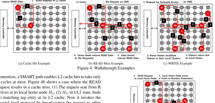
3.4 Walkthrough Examples
The example system is a 64-core CMP employing a8×8 mesh network, which is partitioned into 4 fixed-size local clusters, each comprising4×4tiles; the entire system con-sists of2×2local clusters. For our example, we assume hier-archical L1/L2 cache organization with inclusive L2 cache. L1 cache has MSI states for cache coherence, while L2 cache has MOESI states. We will indicate the specific coherence state for L1 or L2 caches by State:L1 or L2 respectively.
Figure 4a shows the steps involved in a cache hit. (1) Node C, initially in I:L1 state, sends a READ request to local home node H. (2) H, in S:L2 state, returns the data to the requestor. When a cache hit occurs, the request is handled within the cluster by a directory-based protocol, tracking the 16 potential sharers of the cluster. Hence, with no network
Read-Hit
M em o ry C o n tro ller1. READ Request to L2 cache C
H 2. Local Home Node returns READ Data
1
2
(a) Cache Hit Example
Read-Miss
M em o ry C o n tro ller 1. READ Request to L2 Cache R2. L2 Cache Miss: Broadcast the Request on VMS 1 3 2 2 4 2 3. Data Owner returns READ Data 4. Home Node returns READ Data
to the Requestor
H0 H1
H2 H3
2
(b) READ Miss Example
Write
1. Request for Exclusive Access2. Broadcast Inv. Request on VMS M em o ry C o n tro ller W S S H0 H1 H2 H3 3 3 5 6
3. Home Nodes invalidate Sharers in their Local Clusters
4. Sharers return Ack to Local Home 5 & 6. Data & Ack return
4 4 2 2 2 1 (c) WRITE Example
Figure 4: Walkthrough Examples contention, a SMART path enables L2 cache hits to take only
4 cycles at most. Figure 4b shows a case where the READ request results in a cache miss. (1) The request sent from R arrives at its local home nodeH0. (2)H0, in I:L2 state, finds
no matching tag entry at its L2 cache. Now it invokes the second level protocol by broadcasting the request to other clusters on the VMS for the address. The request is delivered to H1, H2, and H3 along SMART links. The request is
sent to off-chip memory as well. (3) To ensure only one sharer returns the data among multiple shares, the one with ownership, i.e. in O state (H1in our example) responds to
the request. For simplicity, this example only shows the case where the data is cached on-chip. If there is no cached data on-chip, the memory controller assumes the ownership and returns the data from off-chip memory. (4) Finally,H0stores
the data into its L2 cache and transits to S:L2 state. Now it goes back to the first level protocol, and returns the data to the requestor,R.
Next, we turn to WRITE operations in Figure 4c. (1) NodeW, in I:L1 state, issues the request for exclusive ac-cess to its local home nodeH0. (2) To get exclusive access
right,H0broadcastsinvalidationrequests on the VMS. (3)
Home nodes in each cluster invalidate their local sharers by the first level protocol. Each home node checks a tag direc-tory to retrieve the local sharer list and invalidates them. (4) Local sharers in S:L1 state transit to I:L1 state, and send ac-knowledgements to local home nodes. (5) After invalidating local sharers, home nodes also transit to I:L2 state. In this example, H1 was in O:L2 state. It sends the data back to
the home node of the requesting cluster,H0. On receiving
the data,H0 changes its state to M:L2 state. (6)W finally
receives the data, and transits to M:L1 state.
Next we will walk through inter-cluster victim replace-ment in Figure 5. (1) A new READ request causes cache replacement at the local home node H0. (2) H0 selects a
victim cache line and sends it to a random destination H1
(3)H1receives the replacement request, and selects a local
victim cache line via timestamp comparison. If the times-tamp of the migrated data is newer,H1stores the migrated
migraton
M em o ry C o n tro ller 1. READ Request to Local Home NodeR
2. Local Home Node evicts a Victim to Random Destination
3. Compare Migrated Data to Local Victim. Evict the older one
H0 H1 H2 H3 1 2 3 4 4. If hits Threshold, write back the Victim
Figure 5: Inter-Cluster Victim Replacement Example data in its L2 cache and evicts its local victim, migrating it to a random destination, repeating the entire process. Other-wise, replacement is denied, and instead the data is steered to another random node. (4)H3receives the victim data and
finds that the replacement counter has hit the threshold. It sends the data as write-back to the off-chip memory.
4.
Evaluation
We implemented LOCO and the underlying SMART NoC (extended for efficient VMS broadcasts) in the C++-based multi-core simulation tool GEMS [34], which incorporates the cycle-accurate network model GARNET [1].
We perform trace-driven simulations for both 64-core and 256-core CMPs by feeding traces generated by Graphite [37]6
into GEMS. We also verify LOCO with full-system simu-lations to provide more realistic evaluation results. As full-system simulations on GEMS lead to unfeasibly long sim-ulation time beyond 64 cores, full-system simsim-ulations were conducted only for 64-core CMP to maintain the simulation time within a week.
We ran SPLASH-2 [44] and PARSEC [8] benchmark suites. Statistics are gathered at the end of the parallel
por-6While Graphite provides fast, scalable full-system simulation up to 1000
cores, it does not at the moment provide a cycle-accurate network model yet, which is crucial for correct evaluation of LOCO.
tion of each benchmark. Simulations run to completion for the 64-core full-system simulations. However, due to simu-lation time limitation, our trace-driven simusimu-lations simulate up to 2 billion memory instructions including cache warm-up sequences.
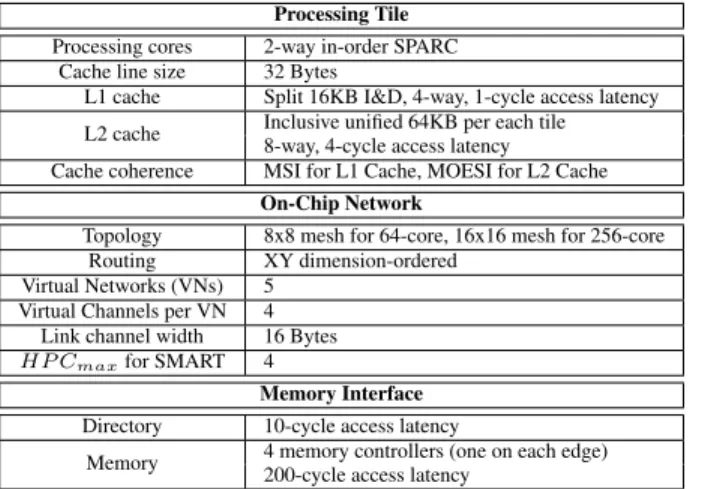
Table 1: Target System Configuration
Processing Tile Processing cores 2-way in-order SPARC
Cache line size 32 Bytes
L1 cache Split 16KB I&D, 4-way, 1-cycle access latency L2 cache Inclusive unified 64KB per each tile
8-way, 4-cycle access latency Cache coherence MSI for L1 Cache, MOESI for L2 Cache
On-Chip Network
Topology 8x8 mesh for 64-core, 16x16 mesh for 256-core
Routing XY dimension-ordered
Virtual Networks (VNs) 5 Virtual Channels per VN 4
Link channel width 16 Bytes
HP Cmaxfor SMART 4
Memory Interface Directory 10-cycle access latency
Memory 4 memory controllers (one on each edge) 200-cycle access latency
4.1 Target CMP System
Our target system consists of strictly hierarchical L1/L2 caches. L1 cache is allowed to communicate only with L2 caches, not directly with other L1 caches. We compare LOCO with two baseline cache organizations: distributed private and shared caches. Both baseline cache organiza-tions and LOCO naturally get performance benefits from SMART NoCs, since all multi-hop traversals can now take just a single cycle. By running all cache organizations over SMART NoCs, we seek to highlight that the performance improvement over the baselines is strictly due to LOCO. Cache Coherence. The baseline configurations operate on a directory-based protocol. When a L1 cache miss occurs, the request is delivered to the local L2 or the static home node in the shared and private L2 respectively. Then, the L2 cache communicates with other L2 caches or memory controllers to retrieve data from the sharers or to invalidate all shared data copies. The sharer information of each cache line is stored in a directory at the home node (shared cache) or at the memory controller (private cache).
LOCO uses 4x4 clusters (Figure 1), unless specified. We use directory-based coherence within clusters, and a broad-cast protocol between clusters. Broadbroad-cast protocols assume an ordered interconnect, but LOCO’s virtual meshes (VMS) do not provide ordering. As there have been recent proposals such as Token coherence [33] and INSO [2] for maintaining global ordering on a mesh topology, we can apply either one to LOCO. For our evaluations, we used Token Coherence, where a reader is required to have at least one token, while a writer must collect all tokens to obtain exclusive access right. With a L2 cache miss, the request is broadcast to all relevant L2 caches for the cache line address. On receiving
0 0.5 1 1.5 2 2.5 3 N o rm a liz ed R u n ti m e
Figure 6: Normalized runtime of distributed private caches vs. distributed shared caches (64-core).
cache requests, L2 caches respond to the request by return-ing tokens or data.
Directory Storage and Latency Overhead.One important parameter impacting evaluation results is directory access la-tency. For baseline caches, the directory should cover shar-ers across the entire chip. A naive implementation based on a bit-vector, for instance, will require additional 256 bits per each cache line to keep track of sharers for a 256-core system, which is the same amount of storage needed for our 32-byte cache line. In contrast, a cluster-based approach like LOCO requires just a 16-bit vector for tracking sharers within the cluster. Directory storage overhead is one of key problems in maintaining scalability of directory-based pro-tocols. There have been a plethora of suggestions such as sparse directory [17] or hierarchical directory [42] to mit-igate directory storage overhead with a trade-off between performance and scalability. Addressing the scalability is-sues of a directory-based protocol is beyond the scope of this paper. Instead, we assume that the home node can ac-cess its directory in parallel with an L2 cache acac-cess without additional latency. Further we do not consider any adverse effect of directory storage overhead, which otherwise can be traded off for larger L2 cache capacity. This is a generous assumption for the baseline distributed shared cache organi-zation. LOCO’s inter-cluster broadcast protocol also needs a directory to record the ownership and related state bits, but it requires less storage overhead thanks to clustering. 4.2 Evaluation Results: Trace-Driven Simulation To evaluate the performance of LOCO, we simulated three cache configurations:LOCO CCrepresents LOCO with just local cache clusters managed by a directory-based proto-col providing global coherence. In LOCO CC, when a L2 cache miss occurs, the request is sent to the directory at the memory controller to obtain the sharer list. Next, it either receives a data copy from one of the sharers, or invalidates all sharers upon writes. It should be noted that the traver-sals to/from the directory are expedited through the SMART NoC as well.LOCO CC+VMSadds broadcasting on VMS between LOCO clusters. Finally, LOCO CC+VMS+IVR incorporates inter-cluster victim replacement as well. Private vs Shared Cache.Figure 6 plots the runtimes of pri-vate caches , normalized to that of shared caches, both run-ning atop SMART NoCs. It should be pointed out that base-line shared caches stand to gain more benefit from SMART
NoCs as there is more global, cross-chip traffic compared to private caches. We observe that the performance of pri-vate caches is severely degraded due to high cache miss, on average 2.3 times slower than shared cache. This is due to small L2 cache slice (64KB),7assumed, which is arrived at given our assumption of small 1mm×1mm tiles in a many-core chip. From here onwards, we thus assume distributed shared caches as the baseline for comparison, unless stated otherwise.
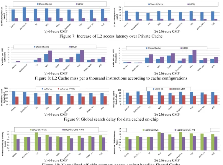
L2 Cache Hit Latency.LOCO’s clustering is designed to provide fast L2 cache access within a cluster, mimicking a large private L2 cache. Figure 7 shows the additional cache access latency of each cache configuration over that of a dis-tributed private cache, i.e. the average latency of the baseline private cache is deducted from the other configurations.
For the 64-core CMP, as shown in Figure 7a, LOCO adds 2.9 cycle-latency on average for L2 cache access than pri-vate cache, while shared cache adds 11.5 cycles on aver-age. Since each SMART-hop takes 2 cycles without network contention, LOCO requires just 1.5 more SMART-hop-delay than private cache, while the baseline shared cache needs ad-ditional 3.7-SMART-hop delay. In other words, since a base-line private caches takes 1-hop to send a request, and 1-hop to receive a response, LOCO takes just 3.5-SMART-hop de-lay on average.
As core counts increase, the benefit of LOCO also in-creases in comparison with shared cache. For 256-core CMP, as shown in Figure 7b, L2 access latency of shared cache in-creases by 4.5 cycles over 64-core CMP, while the latency of LOCO remains relatively unchanged with a marginal in-crease of 0.08 cycles.
L2 Cache Miss Rate. High cache hit rate is another goal of LOCO’s clustering, enabled by the larger cache capacity of an entire cluster. Figure 8 shows L2 cache misses per a thousand instructions of various benchmarks, averaged across the entire simulation time. For 64-core CMP, LOCO increases L2 cache miss moderately over shared cache, by 0.33% for 64-core CMP and by 0.43%for 256-core CMP. Combined with L2 hit latency results above, this shows that LOCO comes reasonably close to our goal of offering low latency benefits of private cache while delivering the high cache hit rate of shared cache at the same time.
Impact of LOCO’s Broadcast over Virtual Meshes. Fig-ure 9 shows the cost involved in searching on-chip cached data with and without VMS, i.e. the average delay needed to find on-chip data stored in other clusters. This delay in-cludes L2 cache access latency, directory latency, and net-work delay. In LOCO without VMS, the search is based on a directory protocol, which incurs indirection latency for directory look-up. As shown in the figures, VMS provide 34.8%reduction in search cost for 64-core, and39.9%for
7We note that we used very small-scale working sets in our simulations for
tractability. In a real system, larger L2 caches will not result in significantly lower cache miss rates with realistic working sets.
256-core, respectively. This reduction is achieved via fast hardware broadcast support for VMS within SMART NoC routers, and by avoiding directory look-up latency. We note that VMS gives higher benefit for 256-core CMP with in-creased network delay.
Impact of LOCO’s inter-cluster victim replacement. An-other goal of LOCO is to effectively utilize on-chip cache ca-pacity to reduce expensive off-chip memory access. LOCO CC+VMS+IVR is designed to address this. Figure 10 com-pares the number of off-chip memory accesses of differ-ent cache configurations, normalized against the baseline shared cache. IVR shows15.6%reduction of off-chip mem-ory access over LOCO CC for 64-core, and17.9%for 256-core. Overall, LOCO CC+VMS+IVR almost matches that of shared cache on average.
It is interesting to note that although shared cache has the largest effective cache capacity, in disallowing any redun-dancy across L2 cache slices, LOCO CC+VMS+IVR some-times outperforms shared cache in reducing off-chip mem-ory access, for example,barnesandswaptionsfor 64-core CMP. This is because LOCO CC+VMS+IVR extends the limited 8-way set-associativity of shared cache by migrat-ing victims to other clusters. In a 64-core CMP, for instance, LOCO effectively creates a 8x4=32-way cache distributed across 4 distant clusters.
Overall Performance.Figure 11a shows normalized run-times of each feature of LOCO progressively, against the baseline shared cache for 64-core CMP with trace-driven simulations. On average, LOCO CC delivers 5.5%reduction in application runtime, LOCO CC+VMS results in further 4.8% reduction, and LOCO CC+VMS+IVR gives an ad-ditional3.7%reduction. Overall, LOCO improves runtime by 13.9%, on average, across all benchmarks. For 256-core CMP, as shown in Figure 11b, LOCO gives higher runtime reduction of17.9%, which shows scalability of LOCO to higher core counts.
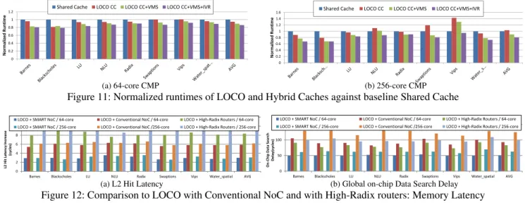
Comparison to LOCO with Alternative NoC Architec-tures. So far, all simulations for both the baselines and LOCO run on top of SMART NoC. To demonstrate that LOCO’s performance is hinged upon SMART NoC’s ca-pability to instantly establish a virtual, single-cycle multi-hop path, we turn to evaluation of LOCO with an alterna-tive NoC architectures: conventional NoC and high-radix routers. When LOCO runs on top of conventional NoC and thus without VMS broadcasting, it is essentially reduced to the baseline clustered cache with increased network latency by stopping at every intermediate router.
High-Radix routers use the same clockless repeated wire technology as SMART, to go up to 4 hops within 1 cycle, and represent an alternate way of leveraging low wire de-lay. We implement a Flattened Butterfly topology [28] which adds dedicated physical links from every router to its 1-hop, 2-1-hop, 3-hop and 4-hop neighbors to enable LOCO to run with 4x4 cluster sizes. Each home node is now always
0 2 4 6 8 10 12 14 L2 Hit La te n cy Incr ease (c yc le s)
Shared Cache LOCO
(a) 64-core CMP 0 5 10 15 20 25 L2 Hit Late n cy In crea se (c yc le s)
Shared Cache LOCO
(b) 256-core CMP
Figure 7: Increase of L2 access latency over Private Cache
0 5 10 15 20 25 30 Cach e Mi ss pe r 1000 In st ruc ti o n s
Shared Cache LOCO
(a) 64-core CMP 0 5 10 15 20 25 30 Cac h e Miss pe r 10 00 In st ru ct io n s
Shared Cache LOCO
(b) 256-core CMP
Figure 8: L2 Cache miss per a thousand instructions according to cache configurations
0 20 40 60 80 100 On ‐ Ch ip Da ta Se ar ch De la y( cycle s) LOCO CC LOCO CC + VMS (a) 64-core CMP 0 20 40 60 80 100 On ‐ Ch ip Da ta Sea rch D e la y(cycles ) LOCO CC LOCO CC+VMS (b) 256-core CMP
Figure 9: Global search delay for data cached on-chip
0 0.2 0.4 0.6 0.8 1 1.2 1.4 N o rm a liz ed Off ch ip Me m o ry A cce ss LOCO CC +VMS LOCO CC+VMS + IVR (a) 64-core CMP 0 0.2 0.4 0.6 0.8 1 1.2 1.4 1.6 Nor m alized Off ch ip Me m o ry A cce ss
LOCO CC+VMS LOCO CC+VMS+IVR
(b) 256-core CMP
Figure 10: Normalized off-chip memory access against baseline Shared Cache 1-cycle away unlike SMART where 1-cycle is
opportunis-tic, and the network has 4x higher bisection throughput be-cause of the additional wires. However, each router is now 20-ported instead of the 5-ported SMART/baseline router, which requires multi-stage arbiters and crossbars, increasing the router pipeline to at least 4-stages [27, 28, 40] unlike the 2-stage SMART router. There is also a 6.7X area and 2.3X power overhead as compared to SMART by modeling both designs in DSENT [41].
Figure 12 shows that conventional NoC and high-radix routers increase both L2 access latency and global on-chip data search delay. For 256-core, the overhead by conven-tional NoC is 2.01x for L2 hit latency, and 1.99x for global on-chip data search delay, while the overhead by high-radix routers is 3.10x for L2 hit latency, and 1.59x for global on-chip data search delay. Figure 13 shows the runtimes normal-ized against shared cache running atop SMART NoC. LOCO with SMART NoC reduces the runtime by 18.9% for 64-core, and by24.6%for 256-core , compared to LOCO with conventional NoC. The increased router latencies of high-radix routers result in22.7%runtime increase for 64-core,
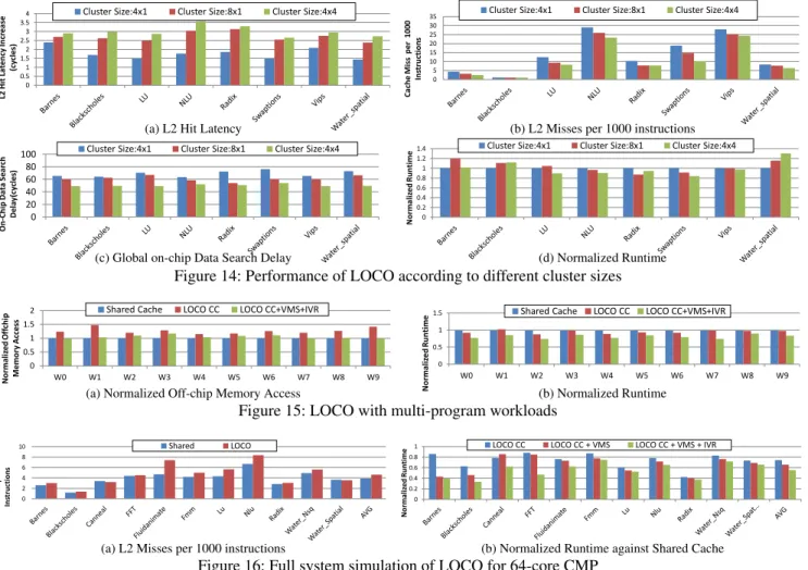
and24.4%increase for 256-core, compared to LOCO with SMART. We note that LOCO with high-radix routers under-perform even LOCO with conventional NoC. This is because high-radix routers increases L2 access latency significantly within a cluster, since the request always go through 4-stage pipelined routers both at the source and at the destination. Cluster Size and Topology.Till now we presented results with 4x4 clusters. Now, for 64-core CMP, we explore the impact of alternative cluster sizes and topology: 4x1 and 8x1. Cluster sizes of 4x1 allow a SMART-hop distance of 1 for every pair of two nodes within the cluster, while cluster sizes of 8x1 and 4x4 have up to 2 SMART-hops. As shown Figure 14a, smaller cluster sizes lead to reduced L2 cache hit latencies; 1.17 and 0.45 cycles are reduced for cluster size 4x1 and 8x1, respectively. However, smaller cluster sizes lead to35%and20% higher L2 cache miss rates on average, as shown in Figure 14b. Cluster size should be chosen considering trade-off between L2 cache hit latency and miss rate. Figure 14d compares the runtimes of LOCO with different cluster sizes. The optimal cluster size and topology is dependent on application, since these trade-offs
0 0.2 0.4 0.6 0.8 1 1.2 N o rma liz ed R unt im e
Shared Cache LOCO CC LOCO CC+VMS LOCO CC+VMS+IVR
(a) 64-core CMP 0 0.2 0.4 0.6 0.8 1 1.2 1.4 1.6 No rm al iz e d Ru ntim e
Shared Cache LOCO CC LOCO CC+VMS LOCO CC+VMS+IVR
(b) 256-core CMP
Figure 11: Normalized runtimes of LOCO and Hybrid Caches against baseline Shared Cache
0 2 4 6 8 10 12
Barnes Blackscholes LU NLU Radix Swaptions Vips Water_spatial AVG
L2 H it L at en cy In cr ea se (c ycle s)
LOCO + SMART NoC / 64-core LOCO + Conventional NoC / 64-core LOCO + High-Radix Routers / 64-core LOCO + SMART NoC / 256-core LOCO + Conventional NoC /256-core LOCO + High-Radix Routers / 256-core
(a) L2 Hit Latency
0 50 100 150
Barnes Blackscholes LU NLU Radix Swaptions Vips Water_spatial AVG
On -C hi p D at a Se ar ch D e la y(c ycle s)
LOCO + SMART NoC / 64-core LOCO + Conventional NoC / 64-core LOCO + High-Radix Routers / 64-core LOCO + SMART NoC / 256-core LOCO + Conventional NoC /256-core LOCO + High-Radix Routers / 256-core
(b) Global on-chip Data Search Delay
Figure 12: Comparison to LOCO with Conventional NoC and with High-Radix routers: Memory Latency
0 0.5 1 1.5
Barnes Blackscholes LU NLU Radix Swaptions Vips Water_spatial AVG
N o rmal iz ed Run ti me
LOCO + SMART NoC / 64-core LOCO + Conventional NoC / 64-core LOCO + High-Radix Routers / 64-core LOCO + SMART NoC / 256-core LOCO + Conventional NoC /256-core LOCO + High-Radix Routers / 256-core
Figure 13: Comparison to LOCO with Conventional NoC and with High-Radix routers: Normalized Runtime
can have different impact on the performance according to application characteristic. For example, cluster size 4x1 has 89.9%higher cache miss rate forswaptionsthan cluster size 4x4, while the increase is mere15.6%forwater spatial. As a result, cluster size 4x1 has the worst runtime forswaptions, while it is the best forwater spatial.
Table 2: Multi-program workloads for 64-core CMP
Work- Description
load Number of instances x Benchmark( Number of Threads ) W0 4xBlackscholes(4), 4xFerret(4), 4xFmm(4), 4xLu(4) W1 4xNlu(4), 4xSwaptions(4), 4xWater Nsq(4), 4xWater Spatial(4) W2 4xBlackscholes(4), 4xFerret(4), 4xWater Nsq(4), 4xWater Spatial(4) W3 4xFmm(4), 4xLu(4), 4xNlu(4), 4xSwaptions(4)
W4 4xBlackscholes(4), 4xFerret(4), 4xNlu(4), 4xSwaptions(4) W5 2xBlackscholes(8), 2xFerret(8), 2xFmm(8), 2xLu(8) W6 2xNlu(8), 2xSwaptions(8), 2xWater Nsq(8), 2xWater Spatial(8) W7 2xBlackscholes(8), 2xFerret(8), 2xWater Nsq(8), 2xWater Spatial(8) W8 1xBlackscholes(16), 1xFerret(16), 1xFmm(16), 1xLu(16) W9 1xNlu(16), 1xSwaptions(16), 1xWater Nsq(16), 1xWater Spatial(16)
Multi-program Workloads. The need for clustering in
cache organization naturally occurs with mapping of het-erogeneous tasks onto CMP, where the memory is shared mostly within the same task. Thus, local L2 caches of cores running the same task can be clustered into a shared cache to provide reduced L2 hit latency within the cluster, while it operates as private cache globally [18, 31, 35]. The result-ing clustered cache is similar to LOCO CC, where the cluster size is determined by the number of threads(cores) required for individual task. One of important design goals in clus-tered cache is to allocate the cache resource among different
tasks for high utilization of on-chip cache, and thus to reduce costly off-line memory access. Several previous works have proposed dynamic reallocation of cache resources adapted by memory demand of each task [18, 31], which, in turn, poses intriguing problem of managing the increased cost of global data search. LOCO can address this problem by inter-cluster victim replacement, which allows one cluster to utilize less utilized cache resource in other clusters across the chip.
In the evaluation, both the baseline clustered cache and LOCO provide shared cache within clusters. On the other hand, each task in the workloads is assumed to have exclu-sive address space with each other, thus the second level cache coherence is not required. The baseline clustered cache is modelled only to provide shared cache and cache coherence within the cluster. Atop the baseline clustered cache, LOCO performs inter-cluster victim replication with faster retrieval of migrated data on VMS in global scale. Table 2 summarizes the workloads used for the evaluation. While LOCO supports flexible heterogeneous clusters in which each cluster can have any size and can be changed at any time as depicted in Figure 1, we assume that all clusters are of the same size while running each workload for the ease of simulation; clustered cache and LOCO have clus-ter size 4x1 for W0 through W4, clusclus-ter size 8x1 for W5 through W8, and cluster size 4x4 for the rest. Each indi-vidual task is mapped onto a single cluster. For example, with the workload W0, every instance of tasks requires 4 threads, thus 64-core CMP is divided into 16 clusters of size 4x1. As there are 4 instances ofbarnes, 4 clusters run their own instance ofbarnesindependently, another 4 clus-ters runblackscholes, and so on. For all cache organizations, the same SMART NoC withHP Cmax = 4 is applied as
usual. Figure 15a shows off-chip memory access normalized against shared cache. On average, clustered cache increases off-line memory access by26.6%, while LOCO reduces
off-0 0.5 1 1.5 2 2.5 3 3.5 4 L2 H it L at e n cy In cr ea se (cy cl es )
Cluster Size:4x1 Cluster Size:8x1 Cluster Size:4x4
(a) L2 Hit Latency
0 5 10 15 20 25 30 35 C ache Mi ss p er 1 00 0 In st ructi on s
Cluster Size:4x1 Cluster Size:8x1 Cluster Size:4x4
(b) L2 Misses per 1000 instructions
0 20 40 60 80 100 On -C h ip D at a Se ar ch D ela y(cy cle s)
Cluster Size:4x1 Cluster Size:8x1 Cluster Size:4x4
(c) Global on-chip Data Search Delay
0 0.2 0.4 0.6 0.8 1 1.2 1.4 N o rma liz e d Ru n ti me
Cluster Size:4x1 Cluster Size:8x1 Cluster Size:4x4
(d) Normalized Runtime
Figure 14: Performance of LOCO according to different cluster sizes
0 0.5 1 1.5 2 W0 W1 W2 W3 W4 W5 W6 W7 W8 W9 N orma liz ed O ff ch ip Mem ory Ac ce ss
Shared Cache LOCO CC LOCO CC+VMS+IVR
(a) Normalized Off-chip Memory Access
0 0.5 1 1.5 W0 W1 W2 W3 W4 W5 W6 W7 W8 W9 N o rma liz ed Ru n ti me
Shared Cache LOCO CC LOCO CC+VMS+IVR
(b) Normalized Runtime
Figure 15: LOCO with multi-program workloads
0 2 4 6 8 10 C ache Mi ss p er 1 00 0 In st ruct ion s Shared LOCO
(a) L2 Misses per 1000 instructions
0 0.2 0.4 0.6 0.8 1 N orma liz ed Run time
LOCO CC LOCO CC + VMS LOCO CC + VMS + IVR
(b) Normalized Runtime against Shared Cache
Figure 16: Full system simulation of LOCO for 64-core CMP line memory access to almost the same level as shared cache,
just5.1%higher than shared cache. As a result, Figure 15b shows that LOCO reduces the runtime of clustered cache by 13.8%, which is 20%improvement over shared cache.
4.3 Full System Simulations
Trace-driven simulations do not properly capture dependen-cies between instructions that cause busy-waiting or spin-ning, which can have high performance impact. In this sec-tion, we present full system simulation results to evaluate the performance of LOCO more realistically. Due to tool limita-tion, we conducted full system simulations only for 64-core CMP. We leave verifying LOCO with full system simula-tions at high core counts as future work.
Figure 16b shows normalized runtimes for PARSEC and SPLASH-2 benchmarks8against shared cache. On average,
LOCO CC delivers 26% reduction in application runtime, LOCO CC+VMS further results in8%reduction, and LOCO CC+VMS+IVR gives an additional10%reduction. Overall,
8For full system simulations, we were unable to obtain results ofswaptions
andvipsdue to long simulation time. Instead, we added results ofcanneal,
fft,fmm fluidanimate, andwater nsq, which in turn, failed in trace-driven
simulations due to out-of-memory errors.
LOCO improves runtime by 44.5%on average. We note that benchmarks such asblackscholes,lu, andradix, show sig-nificantly reduced runtime with just clustering. In contrast,
barnesandfft are not improved much by only clustering. This is because the communication pattern in the first group is highly concentrated between neighboring cores, while the latter group exhibits widely distributed communication pat-terns across the die [5]. Although the latter benchmarks lack locality by nature, LOCO successfully reduces the runtimes ofbarneswith VMS, orfftwith IVR, giving consistent per-formance improvement across the benchmarks.
5.
Related Work
For the first time, SMART NoC provides a practical mech-anism by which any core withinHmax hops away can be
reached in a single cycle, at any time. LOCO leverages this unique mechanism with adaptive cluster sizes, vir-tual meshes for inter-cluster broadcasts, and using remote nodes for storing victims. None of these make sense without SMART, and as we will next discuss, many prior cache orga-nizations will work better with SMART, but none leverages SMART as well as LOCO.
Locality-optimized data placement. There has been a plethora of recent studies that optimizes locality for higher performance. One such approach is the dynamic mapping of pages to L2 cache slices in a shared cache, often with the aid of the OS [3, 10, 14, 15, 19]. There has been significant work on improving data locality at the cache line granularity as well. Cache line is relocated closer to the core [12, 26], or replicated into the local L2 cache [45, 46], which can be further improved by selective replication [7, 13].
All these works will have to be reformulated to leverage SMART NoCs. For instance, with SMART, locality-aware mapping or replication need no longer be limited to a local L2 cache slice, but instead, can be expanded to all L2 caches withinHmax. Similarly, we can remove unnecessary
redun-dancy by retaining only a single copy of data within a radius ofHmax. In fact, these are exactly the observations that
mo-tivated LOCO’s clustering. However, unlike these previous approaches, LOCO is not only concerned with data locality, but also leverages SMART NoC to maximize cache utiliza-tion by way of inter-cluster broadcasts and victim replace-ment.
Clustered cache organizations. Hierarchical or clustered caches have been proposed as a scalable cache solution by many researchers. In [32, 42], the communication bottleneck to a central directory is mitigated by distributing hierarchical directories across the chip. More recent studies have focused on providing flexible sized clusters to best serve application demands [9, 18, 23, 31, 35]. LOCO provides an efficient mechanism for supporting flexible clusters while maintain-ing coherence and balancmaintain-ing cache utilization across clus-ters with IVR, unlike the complex hardware monitoring and remapping mechanisms required by prior techniques.
In this paper, we did not focus on the policies for deter-mining the most appropriate cluster size, as this depends on the applications’ working sets and/or aggregate cache requirement [18, 23, 31, 35]. To find optimal cluster size, LOCO can leverage previous works which flexibly adjust cluster sizes according to the cache performance [18, 23, 31].
Cache search and coherence.Substantial research has pro-posed flexible data location in L2 cache slices, which leads to the additional overhead of searching for the current data location. Here, we focus on search techniques that manages at the granularity of cache lines. One approach is to use a central tag to keep track of dynamic locations of each cache line [9, 12]. As a central tag directory might be a communi-cation bottleneck, several researchers employed local tag di-rectories instead [13, 24, 35]. A local tag directory can only function as a backup, since it is impossible to assign to every core its own tag directory covering the entire on-chip cached memory. The most common strategy is to maintain the tag directory at static home node locations [19, 24, 31, 45, 46], while actual data can be stored at other places. This leads
to an indirection cost to access the home node whenever ac-cessing data.
To avoid this indirection cost, broadcast can be used [7, 12, 13, 18, 26, 35, 36]. However broadcasting over large-scale CMPs is simply unacceptable in terms of latency and energy consumption. The broadcasting cost is mitigated by using local tag directories as caches [13, 35], or by broad-casting only to relevant destinations [18, 36], which is sim-ilar to our approach. In this paper, we further optimize broadcast latency with our virtual meshes (VMS) leveraging SMART NoC (Section 3.2), which offers a scalable solution to many-core CMPs.
Co-design of cache organization with novel intercon-nects.There have been prior studies that investigate alter-native cache designs driven by emerging interconnect tech-nologies as well. Transmission line caches [6] enable area and energy-efficient cache organization by exploiting on-chip transmission lines which can substantially reduce wire delay at the cost of wire bandwidth density. ATAC [30] lever-ages on-chip optical links as a high-bandwidth, low-energy broadcast bus for scalable broadcast-based coherence. Like these prior works, LOCO is motivated by novel intercon-nects, SMART. However, LOCO is not limited to a specific topology of custom-designed links determined at the design time, due to the flexible nature of SMART NoC. LOCO can adapt to applications or programmers’ needs, and thus tailor a cache organization to SMART characteristics so as to truly be locality-oblivious.
6.
Conclusion
This work presents LOCO, a locality-oblivious cache orga-nization scheme that leverages recent innovations in low-latency NoC architectures to redefine the notion of local-ity. SMART NoCs enable flits to traverse up toHP Cmax
-hops (4 in this design) within one cycle at 2GHz. LOCO is a hybrid private-shared cache organization that partitions the chip into virtual clusters of varying sizes. It provides in-creased hit rate within each cluster with fast access latencies, and fast global data search across chip over virtual meshes. It also enables data migration across clusters to reduce off-chip accesses. LOCO demonstrates better performance than both private and shared caches, and provides a scalable cache organization and management solution as we move towards 1000-core chips.
Acknowledgments
The authers acknowledge the support of Semiconductor search Corporation (SRC) and the Defense Advanced Re-search Projects Agency (DARPA) through the Semiconduc-tor Technology Advanced Research network (STARnet), un-der the Center for Future Architectures (C-FAR) research center.
References
[1] N. Agarwal, T. Krishna, L.-S. Peh, and N. K. Jha. Garnet: A detailed on-chip network model inside a full-system
simula-tor. InISPASS, 2009.
[2] N. Agarwal, L.-S. Peh, and N. K. Jha. In-network snoop or-dering (inso): Snoopy coherence on unordered interconnects.
InHPCA, 2009.
[3] M. Awasthi, K. Sudan, R. Balasubramonian, and J. B. Carter. Dynamic hardware-assisted software-controlled page place-ment to manage capacity allocation and sharing within large
caches. InHPCA, 2009.
[4] R. Balasubramonian, N. P. Jouppi, and N. Muralimanohar. Multi-Core Cache Hierarchies. Synthesis Lectures on Com-puter Architecture. Morgan & Claypool Publishers, 2011. [5] N. Barrow-Williams, C. Fensch, and S. W. Moore. A
com-munication characterisation of splash-2 and parsec. InIISWC,
2009.
[6] B. M. Beckmann and D. A. Wood. TLC: Transmission Line
Caches. InMICRO, 2003.
[7] B. M. Beckmann, M. R. Marty, and D. A. Wood. Asr:
Adap-tive selecAdap-tive replication for cmp caches. InMICRO, 2006.
[8] C. Bienia, S. Kumar, J. P. Singh, and K. Li. The parsec bench-mark suite: characterization and architectural implications. In
PACT, 2008.
[9] J. Chang and G. S. Sohi. Cooperative caching for chip
multi-processors. InISCA, 2006.
[10] M. Chaudhuri. Pagenuca: Selected policies for page-grain locality management in large shared chip-multiprocessor
caches. InHPCA, 2009.
[11] C.-H. O. Chen, S. Park, T. Krishna, S. Subramanian, A. P. Chandrakasan, and L.-S. Peh. SMART: A Single-Cycle
Re-configurable NoC for SoC Applications. InDATE, 2013.
[12] Z. Chishti, M. D. Powell, and T. N. Vijaykumar. Distance as-sociativity for high-performance energy-efficient non-uniform
cache architectures. InMICRO, 2003.
[13] Z. Chishti, M. D. Powell, and T. N. Vijaykumar. Optimizing replication, communication, and capacity allocation in cmps.
InISCA, 2005.
[14] S. Cho and L. Jin. Managing distributed, shared l2 caches
through os-level page allocation. InMICRO, 2006.
[15] B. Cuesta, A. Ros, M. E. G´omez, A. Robles, and J. Duato. In-creasing the effectiveness of directory caches by deactivating
coherence for private memory blocks. InISCA, 2011.
[16] N. Eisley, L.-S. Peh, and L. Shang. Leveraging on-chip net-works for data cache migration in chip multiprocessors. In
PACT, 2008.
[17] A. Gupta, W.-D. Weber, and T. C. Mowry. Reducing memory and traffic requirements for scalable directory-based cache
coherence schemes. InICPP (1), 1990.
[18] M. Hammoud, S. Cho, and R. G. Melhem. Dynamic cache
clustering for chip multiprocessors. InICS, 2009.
[19] N. Hardavellas, M. Ferdman, B. Falsafi, and A. Ailamaki. Reactive nuca: near-optimal block placement and replication
in distributed caches. InISCA, 2009.
[20] R. Ho. On-Chip Wires: Scaling and Efficiency. PhD thesis,
Stanford University, 2003.
[21] Y. Hoskote, S. R. Vangal, A. Singh, N. Borkar, and S. Borkar.
A 5-ghz mesh interconnect for a teraflops processor. IEEE
Micro, 27(5):51–61, 2007.
[22] J. Howard, S. Dighe, S. R. Vangal, G. Ruhl, N. Borkar, S. Jain, V. Erraguntla, M. Konow, M. Riepen, M. Gries, G. Droege, T. Lund-Larsen, S. Steibl, S. Borkar, V. K. De, and R. F. V. der Wijngaart. A 48-Core IA-32 Message-Passing Processor
with DVFS in 45nm CMOS. InISSCC, 2010.
[23] J. Huh, C. Kim, H. Shafi, L. Zhang, D. Burger, and S. W. Keckler. A nuca substrate for flexible cmp cache sharing. In
ICS, 2005.
[24] N. D. E. Jerger, L.-S. Peh, and M. H. Lipasti. Virtual tree coherence: Leveraging regions and in-network multicast trees
for scalable cache coherence. InMICRO, 2008.
[25] B. Kim and V. Stojanovic. Characterization of equalized and
repeated interconnects for noc applications.IEEE Design and
Test of Computers, 25:430–439, 2008.
[26] C. Kim, D. Burger, and S. W. Keckler. An adaptive, non-uniform cache structure for wire-delay dominated on-chip
caches. InASPLOS, 2002.
[27] J. Kim, W. J. Dally, B. Towles, and A. K. Gupta.
Microarchi-tecture of a high-radix router. InISCA, 2005.
[28] J. Kim, W. J. Dally, and D. Abts. Flattened butterfly: a
cost-efficient topology for high-radix networks. InISCA, 2007.
[29] T. Krishna, C.-H. O. Chen, W. C. Kwon, and L.-S. Peh.
Break-ing the on-chip latency barrier usBreak-ing SMART. InHPCA, 2013.
[30] G. Kurian, J. E. Miller, J. Psota, J. Eastep, J. Liu, J. Michel, L. C. Kimerling, and A. Agarwal. ATAC: All-to-All
Comput-ing UsComput-ing On-Chip Optical Interconnects. InBARC, 2007.
[31] H. Lee, S. Cho, and B. R. Childers. Cloudcache: Expanding
and shrinking private caches. InHPCA, 2011.
[32] Y.-C. Maa, D. K. Pradhan, and D. Thi´ebaut. A hierarchical directory scheme for large-scale cache-coherent
multipmces-sors. InIPPS, 1992.
[33] M. M. K. Martin, M. D. Hill, and D. A. Wood. Token
co-herence: Decoupling performance and correctness. InISCA,
2003.
[34] M. M. K. Martin, D. J. Sorin, B. M. Beckmann, M. R. Marty, M. Xu, A. R. Alameldeen, K. E. Moore, M. D. Hill, and D. A. Wood. Multifacet’s general execution-driven multiprocessor
simulator (gems) toolset. SIGARCH Computer Architecture
News, 33(4):92–99, 2005.
[35] M. R. Marty and M. D. Hill. Virtual hierarchies to support
server consolidation. InISCA, 2007.
[36] M. R. Marty, J. D. Bingham, M. D. Hill, A. J. Hu, M. M. K. Martin, and D. A. Wood. Improving multiple-cmp systems
using token coherence. InHPCA, 2005.
[37] J. E. Miller, H. Kasture, G. Kurian, C. G. III, N. Beckmann, C. Celio, J. Eastep, and A. Agarwal. Graphite: A distributed
parallel simulator for multicores. InHPCA, 2010.
[38] S. Park, T. Krishna, C.-H. Chen, B. Daya, A. Chandrakasan, and L.-S. Peh. Approaching the theoretical limits of a mesh
NoC with a 16-node chip prototype in 45nm SOI. InDAC, 2012.
[39] K. Sankaralingam, R. Nagarajan, H. Liu, C. Kim, J. Huh, D. Burger, S. W. Keckler, and C. R. Moore. Exploiting ilp,
tlp, and dlp with the polymorphous trips architecture. IEEE
Micro, 23(6):46–51, 2003.
[40] S. Scott, D. Abts, J. Kim, and W. J. Dally. The BlackWidow
high-radix clos network. InISCA, 2006.
[41] C. Sun, C.-H. O. Chen, G. Kurian, L. Wei, J. Miller, A. Agar-wal, L.-S. Peh, and V. Stojanovic. DSENT - a tool connect-ing emergconnect-ing photonics with electronics for opto-electronic
networks-on-chip modeling. InNoCS, 2010.
[42] D. A. Wallach. PHD: A Hierarchical Cache Coherent
Proto-col. MS Thesis. MIT, 1992.
[43] D. Wentzlaff, P. Griffin, H. Hoffmann, L. Bao, B. Edwards, C. Ramey, M. Mattina, C.-C. Miao, J. F. B. III, and A. Agar-wal. On-chip interconnection architecture of the tile proces-sor.IEEE Micro, 27(5):15–31, 2007.
[44] S. C. Woo, M. Ohara, E. Torrie, J. P. Singh, and A. Gupta. The splash-2 programs: Characterization and methodological
considerations. InISCA, 1995.
[45] M. Zhang and K. Asanovic. Victim migration: Dynamically adapting between private and shared cmp caches. Technical report, MIT, 2005.
[46] M. Zhang and K. Asanovic. Victim replication: Maximizing capacity while hiding wire delay in tiled chip multiprocessors.

![Figure 2: SMART: Single-cycle Multi-hop Asynchronous Repeated Traversal [29]](https://thumb-us.123doks.com/thumbv2/123dok_us/10173582.2919643/4.918.136.792.119.329/figure-smart-single-cycle-multi-asynchronous-repeated-traversal.webp)