Resource Allocation for Coordinated
Multipoint Joint Transmission System
and Received Signal Strength Based
Positioning in Long Term Evolution
Network
Thesis submitted in accordance with the requirements of the University of Liverpool for the degree of Doctor in Philosophy
By Yang Li
ii
Declaration
The work in this thesis is based on research carried out at the University of Liverpool. No part of this thesis has been submitted elsewhere for any other degree or qualification and it is all my own work unless referenced to the contrary in the text.
Yang Li Liverpool, United Kingdom
iii
Abstract
The Long-Term Evolution Advanced (LTE-A) system are expected to provide high speed and high quality services, which are supported by emerging technologies such as Coordinated Multipoint (CoMP) transmission and reception. Dynamic resource allocation plays a vital role in LTE-A design and planning, which is investigated in this thesis. In addition, Received Signal Strength (RSS) based positioning is also investigated in orthogonal frequency division multiplexing (OFDM) based wireless networks, which is based on an industry project.
In the first contribution, a physical resource blocks (PRB) allocation scheme with fuzzy logic based user selection is proposed. This work considers three parameters and exploit a fuzzy logic (FL) based criterion to categorize users. As a result, it enhances accuracy of user classification. This work improves system capacity by a ranking based PRBs allocation schemes. Simulation results show that proposed fuzzy logic based user selection scheme improves performance for CoMP users. Proposed ranking based greedy allocation algorithm cut complexity in half but maintain same performance.
In the second contribution, a two-layer proportional-fair (PF) user scheduling scheme is proposed. This work focused on fairness between
iv
CoMP and Non-CoMP users instead of balancing fairness in each user categories. Proposed scheme jointly optimizes fairness and system capacity over both CoMP and Non-CoMP users. Simulation results show that proposed algorithm significantly improves fairness between CoMP and Non-CoMP users.
In the last contribution, RSS measurement method in LTE system is analyzed and a realizable RSS measurement method is proposed to fight against multipath effect. Simulation results shows that proposed method significantly reduced measurement error caused by multipath. In RSS based positioning area, this is the first work that consider exploiting LTE’s own signal strength measurement mechanism to enhance accuracy of positioning. Furthermore, the proposed method can be deployed in modern LTE system with limited cost.
v
Acknowledgement
Firstly, I would like to express my sincere gratitude to my supervisor Dr. Xu Zhu, for the continuous support of my Ph.D. study, for her great patience and immense knowledge. Her guidance helped me in all the time of research and life. I also appreciate warm helps from Prof. Yi Huang.
I am grateful to everyone in the Wireless Communication and Smart Grid group: Dr. Yufei Jiang, Mr. Teng Ma, Mr. Chaowei Liu, Dr. Chao Zhang, Dr. Jun Yin, Mr. Kainan Zhu, Mr. Qinyuan Qian, Dr. Zhongxiang Wei, Dr. Linhao Dong, for all the support and encouragement, research views, the greatest dishes and dinner parties.
I would like to thank Ms. Zhenzhen Song for the constant support and encouragement. I couldn’t make it without you.
vi
Contents
Declaration ... ii Abstract ...iii Acknowledgement ... v Contents ... viList of Figures ...viii
List of Tables ... x
Abbreviations ... xi
Mathematical Notations ... xiv
1. Introduction ... 1 1.1 Motivation ... 1 1.2 Research Contributions ... 3 1.3 Thesis Organization ... 5 1.4 Publication List ... 6 2. Wireless Communication ... 7
2.1 Wireless Communication Channels ... 7
2.1.1 Large-Scale Path Loss ... 7
2.1.2 Small-Scale Fading ... 9
2.2 Wireless Communication Systems ... 15
2.2.1 Overview of Wireless Communication Systems ... 15
2.2.2 OFDM Technique ... 17
2.2.3 Coordinated Multipoint Transmission and Reception ... 22
3. Overview of Resource Allocation for Broadband Wireless System ... 26
3.1 Radio Resources in OFDM based Broadband Wireless Systems ... 26
3.2 Resource Allocation in OFDM based Broadband Wireless System ... 28
3.2.1 Physical Layer Resource Allocation... 28
3.2.2 Cross-Layer Optimization ... 31
3.3 Fuzzy Logic ... 33
4. Resource Allocation for LTE System with Coordinated Multipoint ... 38
4.1 System Model ... 41
4.2 PRB Allocation with Fuzzy Logic based User Selection ... 43
vii
4.2.2 CoMP User Selection with PRBs Limitation ... 45
4.2.3 Fuzzy Logic based Ranking Criterion ... 48
4.2.4 PRBs Allocation Algorithms in CoMP ... 53
4.2.5 Simulation Results ... 55
4.3 Two-Layer Proportional-Fair User Scheduling ... 69
4.3.1 Problem Formulation ... 70
4.3.2 Two-Layer Proportional-Fair Scheduler ... 71
4.3.3 Simulation Results ... 72
4.4 Summary ... 81
5. RSS based Positioning for Cellular Networks ... 82
5.1 Low-complexity Positioning with Unknown Path Loss Exponent ... 88
5.1.1 System Model... 88
5.1.2 Simplified Trilateration ... 90
5.1.3 PLE Searching ... 92
5.1.4 Simulation Results ... 93
5.2 Multipath Reduced RSS Measurement in LTE System... 95
5.2.1 System Model... 95
5.2.2 Multipath Reduction in RSS Measurement ... 96
5.2.3 Simulation Results ... 100
5.3 Summary ... 102
6. Conclusions and Future work ... 104
6.1 Conclusions ... 104
6.2 Future Work... 105
Appendix A ... 107
viii
List of Figures
2.1: Four types of small-scale fading according to several parameters ... 13
2.2: Block diagram of the OFDM transmission system ... 17
2.3: Coordinated Multipoint system in JP mode ... 23
2.4: Coordinated Multipoint system in CS/CB mode ... 24
3.1: Physical resource block ... 27
3.2: Water-filling algorithm ... 30
3.3: Fuzzy logic system architecture ... 34
3.4: Shape of basic membership functions ... 35
3.5: Example of fuzzy membership function ... 36
4.1. Membership functions of inputs and output. ... 51
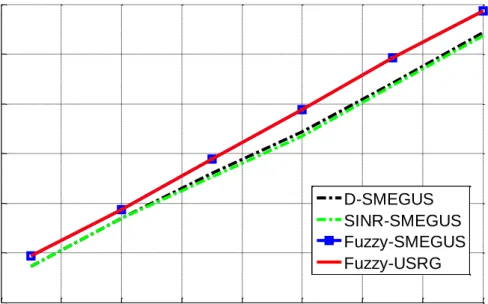
4.2: Average spectral efficiency of edge users, 20% of users are CoMP user, U=0.4*K ... 57
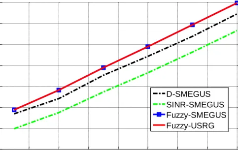
4.3: Average spectral efficiency of edge users, 20% of users are CoMP user, U=K . 58 4.4: Average spectral efficiency of edge users, 80% of users are CoMP user, U=0.4*K ... 58
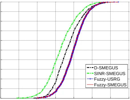
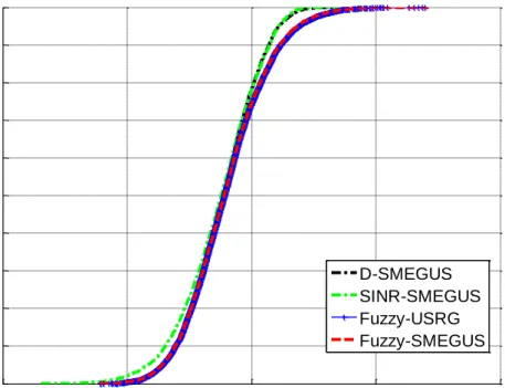
4.5: Average spectral efficiency of edge users, 80% of users are CoMP user, U=K . 59 4.6: CDF of spectral efficiency of edge users, with SNR=6dB, 20% of users are CoMP user, U=0.4*K ... 59
4.7: CDF of spectral efficiency of edge users, with SNR=6dB, 20% of users are CoMP user, U=K ... 60
4.8: CDF of spectral efficiency of edge users, with SNR=6dB, 80% of users are CoMP user, U=0.4*K ... 60
4.9: CDF of spectral efficiency of edge users, with SNR=6dB, 80% of users are CoMP user, U=K ... 61
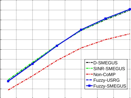
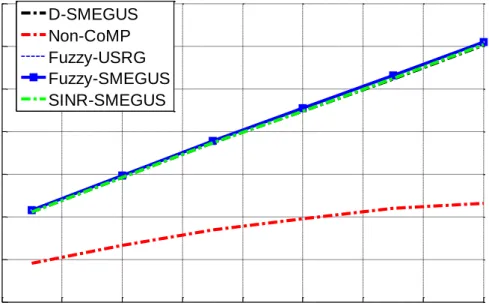
4.10: System throughput, 20% of users are CoMP user, U=0.4*K ... 62
4.11: System throughput, 20% of users are CoMP user, U=K ... 62
4.12: System throughput, 80% of users are CoMP user, U=0.4K ... 63
4.13: System throughput, 80% of users are CoMP user, U=K ... 63
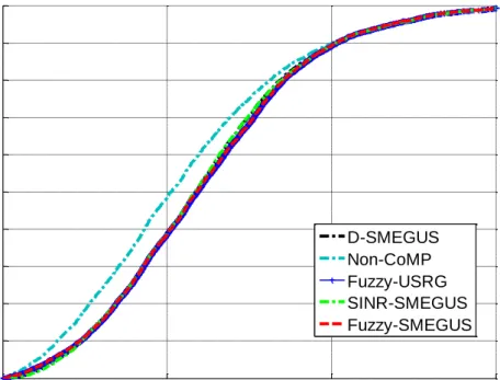
4.14: CDF of spectral efficiency of all users, with SNR=6dB, 20% of users are CoMP user, U=0.4*K ... 64
4.15: CDF of spectral efficiency of all users, with SNR=6dB, 20% of users are CoMP user, U=K ... 64
4.16: CDF of spectral efficiency of all users, with SNR=6dB, 80% of users are CoMP user, U=0.4*K ... 65
4.17: CDF of spectral efficiency of all users, with SNR=6dB, 80% of users are CoMP user, U=K ... 65 4.18: Average spectral efficiency of edge users, 30% of users are CoMP user, U=K 66
ix
4.19: Average spectral efficiency of edge users from FL methods with different input combinations, 20% of users are CoMP user, U=K ... 66 4.20: Average spectral efficiency of edge users from FL methods with different membership functions, 20% of users are CoMP user, U=K ... 67 4.20: Two-layer PF user scheduler ... 73 4.21: Fairness performance of Two-layer PF and classic PF scheduling, when 20% users are CoMP candidates. ... 74 4.22: System throughput of Two-layer PF and classic PF scheduling, when 20% users are CoMP candidates. ... 75 4.23: Fairness performance of Two-layer PF and classic PF scheduling, when 50% users are CoMP candidates ... 76 4.24: System throughput of Two-layer PF and classic PF scheduling, when 50% users are CoMP candidates ... 77 4.25: Fairness performance of Two-layer PF and classic PF scheduling, when 80% users are CoMP candidates ... 78 4.26: System throughput of Two-layer PF and classic PF scheduling, when 80% users are CoMP candidates ... 78 5.1: Simplified Trilateration with (a) scenario I; (b) scenario II. ... 91 5.2: CDF performance comparison between NLS and PLES with 0, 3 and 6 dB shadowing ... 93 5.3: Variance of measured signal power of two methods ... 100 5.4: Measured signal power diversity of two methods ... 101 5.5: Mean positioning error of two RSS measurement methods with known PLE and LS method. ... 102
x
List of Tables
2.1: PL Exponent in Different Environments ... 8
2.2: Four Types of Small-Scale Fading ... 11
2.3: Comparison of mobile telephony standards ... 18
3.1: Membership Function Name ... 35
4.1. Simulation Setup ... 56
4.2. Complexity of CoMP PRB Allocation Algorithms with User Selection ... 69
4.3. Time of execution of two PF algorithm in simulation ... 80
5.1: Complexity Comparison ... 94
xi
Abbreviations
2G second generation
3G third generation
3GPP 3rd generation partnership project
ANN artificial neural network
AOA angle-of-arrival
CDF cumulative distribution function
CDMA2000 code division multiple access 2000
CIR channel impulse response
CoMP coordinated multipoint
CS/CB coordinated scheduling or beamforming
DCEM dynamic circle expanding mechanism
eNB eNodeB
EV-DO evolution-data optimized
EXP-PF exponential proportional fair
FL fuzzy logic
FP fingerprinting
GPS global positioning system
xii
HSPA high speed packet access
ICI inter-cell interference
ISI inter-symbol interference
JP joint processing
LLS linear least square
LMU location measurement unit
LS least square
LTE long term evolution
LTE-A long term evolution advanced
ML maximum likelihood
M-LWDF modified largest weighted delay first
NLLS non-linear least square
OFDM orthogonal frequency division multiplexing
PAPR high peak-to-average power ratio
PF proportional-fair
PL path loss
PLE path loss exponent
PLES path loss exponent searching
PRB physical resource blocks
QoE quality of experience
QoS quality of service
xiii
RN reference nodes
RS reference signal
RSRP reference signal received power
RSS received signal strength
SDP semi-definite programming
SINR interference and noise ratio
SMEGUS simplified mean enhanced greedy
ST simplified trilateration
TDMA time-division multiple access
UE user equipment
UMTS universal mobile telecommunications system
USRG user selection ranking greedy
xiv
Mathematical Notations
𝑙𝑜𝑔10(𝑥) Logarithmic of x with base 10.𝐸(∙) Statistical expectation. ∑ Sum operator. ∏ Multiplication operator. 𝑒𝑥 Exponential function of x. 𝑒𝑥𝑝(𝑥) Exponential function of x. 𝑥̅ Average of x. ⊗ Convolution. 𝑥 ∈ 𝐗 x is an element of set X.
∀𝑥 ∈ 𝐗 x can be any element of set X.
𝑎𝑟𝑔 𝑚𝑖𝑛/𝑚𝑎𝑥 Arguments of the minima/maxima
1
Chapter 1
Introduction
1.1 Motivation
In the past decades wireless communications have made a leap forward [1, 2]. Plenty of research activates have been carried out to improve system capacity [3], system coverage [4], quality of service (QoS) [5], and power consumption [6]. Long term evolution (LTE) network has been deployed globally, over 2 billion LTE subscriptions recorded due to early 2017 [7]. In some region LTE-Advanced network has been marketed. Although various techniques have been proved successful in last generation networks, as technology has advanced, much more effective methods of combating the previous problems have gained support [8].
As the fast developing of wireless communication market, the importance of inter-cell interference (ICI) attracts attention [7]. Coordinated Multipoint (CoMP) transmission and reception technologies, including Joint Processing (JP) and Coordinated Scheduling or Beamforming (CS/CB) has been consider as an advanced solution to
2
combating ICI in LTE-A network. With dynamic coordination of multiple geographically separated eNodeBs (eNB), the interference is reduced by being utilized constructively rather than destructively [8]. In addition, coordinated eNBs are able to enhance user equipment’s (UE) received power and connection quality [9]. Meanwhile adaptive resource allocation (RA) and user scheduling plays important roles in multi-carrier based wireless networks [10-13]. System capacity can be improved significantly with optimal dynamic resource allocation algorithms. User scheduling is essential to ensure fair quality of service [14]. Therefore, resource allocation and user scheduling are critical in CoMP system.
User selection is the first challenge in CoMP system. CoMP users require resource from multiple eNBs. With limitation of system resource, CoMP user selection must be accurate to ensure good service quality for both CoMP and Non-CoMP users. Power allocation had been discussed in many works, but frequency resource allocation for CoMP system didn’t get much attention. Frequency resource occupied by CoMP users cannot be used by Non-CoMP users in same cluster. Therefore, fairness among CoMP and Non-CoMP users is another challenge.
Location based service (LBS) is now widely deployed with mass popularity of smart phones. Global position system (GPS) becomes regular accessory of modern cellphones. However, it only operates in open area and energy consumption is high [15]. Network based positioning had been
3
discussed to assist GPS to improve its positioning performance. Received signal strength (RSS) based positioning is the most convenient and cheapest method. User’s distance from base station can be calculated from RSS. With RSS data from multiple base station, user’s location can be determined. The main challenge is that RSS data is affected by many factors. One of the most critical factors is multipath effect [16, 17].
1.2 Research Contributions
In this thesis, a physical resource blocks (PRB) allocation scheme with fuzzy logic (FL) based user selection is presents in the first. By applying this low-complexity scheme UE which locate at cell edge gain an improvement on network performance. After this, a two-layer proportional-fair user scheduling scheme is proposed to maximize CoMP system capacity and maintain fairness between users. In addition, a low-complexity received signal strength (RSS) based positioning algorithm is proposed for an industry project. An analysis of received signal strength measurement in LTE is presented in the end, in which a realizable measurement method is proposed to enhance accurate of RSS based positioning.
The research contributions during this PhD study is presented as the following:
4
A physical resource blocks allocation scheme with fuzzy logic based user selection is proposed. This work is different from existing researches in the following aspects. First, instead of classifying users by single threshold, this work considers three parameters and exploit a fuzzy logic based criterion to categorize users. As a result, it enhances accuracy of user classification. Second, instead of investigating power control scheme to explore capacity potential, this work improves system capacity by a ranking based PRBs allocation schemes. Simulation results show that proposed fuzzy logic based user selection scheme improves system performance, especially for CoMP users. Proposed ranking based greedy allocation algorithm cut complexity in half but maintain same performance.
A two-layer proportional-fair user scheduling scheme is proposed. This work is different from existing works in the following aspects. First, fairness between CoMP and Non-CoMP users are focused instead of balancing fairness in each user categories. Second, proposed scheme jointly optimizes fairness and system capacity over both CoMP and Non-CoMP users. Simulation results show that proposed algorithm significantly improves fairness between CoMP and Non-CoMP users without using predetermined PRBs limitation.
RSS measurement method in LTE system is analyzed and a realizable RSS measurement method is proposed to fight against multipath effect.
5
The contribution of this work is that, in RSS based positioning area, this is the first work that consider exploiting LTE’s own signal strength measurement mechanism to enhance accuracy of positioning. Furthermore, the proposed method is able to be deployed in modern LTE system with limited cost.
1.3 Thesis Organization
The rest of this thesis is organized as follows.
The wireless channels and systems are introduced in Chapter 2. Wireless communication channel models are presented in Section 2.1. In Section 2.2, an overview of wireless communication systems is presented. OFDM technique is also described in Section 2.2.
Literature review on RA of broadband wireless communication systems is presented in Chapter 3. In this chapter, the radio resource in wireless communication are described in Section 3.1. Literature reviews on resource allocation and scheduling are presented in Section 3.2. In Section 3.3, a brief introduction of Fuzzy Logic is presented.
PRB allocation scheme with fuzzy logic user selection and proposed two-layer proportional-fair user scheduling scheme are presents in Chapter 4. Section 4.1 presents the system model. Fuzzy logic based user selection and ranking based PRBs allocation algorithms are presented in Section 4.2.
6
Two-layer proportional-faire user scheduling is presented in Section 4.3. Section 4.4 presents the summary.
In Chapter 5, low-complexity RSS based positioning algorithm is presented, followed by analysis of proposed RSS measurement method in LTE. The low-complexity positioning method is presented in Section 5.1. The multipath reduced RSS measurement method is presented in Section 5.2. Section 5.3 gives the summary.
Conclusions and future work are presented in the final chapter.
1.4 Publication List
Conference Paper
1. Y. Li, X. Zhu, Y. Jiang, Y. Huang, and E. G. Lim, "Energy-efficient positioning for cellular networks with unknown path loss exponent,"
IEEE International Conference on Consumer Electronics - Taiwan, pp. 502-503, 2015 [18]
7
Chapter 2
Wireless Communication
Channel and System
Wireless communication channel models are presented in Section 2.1. In Section 2.2, an overview of wireless communication systems is presented. OFDM technique is also described in Section 2.2.
2.1 Wireless Communication Channels
2.1.1
Large-Scale Path Loss
When an electromagnetic wave propagates from transmitter to the receiver, its signal strength decreases over distances. This reduction in power density is refereed as large-scale path loss (PL). Normally path loss is caused by diffraction, absorption, and the natural expansion of electromagnetic wave. After travelling the distance 𝑑, the received signal power 𝑃𝑟 at receiver can be expressed as [19]
8
𝑃𝑟(𝑑) = 𝑃𝑡𝐺𝑡𝐺𝑟𝜆 2
(4𝜋)2𝑑𝛼𝐿 (2.1)
where 𝑃𝑡 is transmitted power, 𝐺𝑡 and 𝐺𝑟 are transmitter and receiver antenna gains, respectively, 𝜆 is wavelength of radio wave, 𝐿 represents
system loss which is not related to propagation, 𝛼 represents path loss
exponent. Table 2.1 shows some typical value of PL exponent based on measured data.
Table 2.1: PL Exponent in Different Environments [19]
Environments PL Exponent Free space 2 Urban area 2.7 to 3.5 Shadowed urban 3 to 5 In building line-of-sight 1.6 to 1.8 Obstructed in building 4 to 6 Obstructed in factories 2 to 3
The path loss is defined as reduction of signal power between transmitter and receiver, which can be expressed as [19]
𝑃𝐿(𝑑) =𝑃𝑡 𝑃𝑟 =
(4𝜋)2𝑑𝛼𝐿
9
Rewrite (2.2) in dB,
𝑃𝐿(𝑑) = 𝑃𝐿0+ 10𝛼𝑙𝑜𝑔10(𝑑) (2.3)
where 𝑃𝐿0 = 10𝑙𝑜𝑔10(4𝜋)2𝐿
𝐺𝑡𝐺𝑟𝜆2 [15]. From (2.3), PL is mainly affected by
the transmitted distance and PL plays an important role in wireless network planning and design [19].
2.1.2
Small-Scale Fading
Small-scale fading is the small and fast fluctuation of signal after travelling short time or distance. In urban area, receivers are normally blocked by obstruction from transmitter and line-of-sight path is not available for transmitting signal. The radio wave travels along several different paths to receiver with reflection, diffraction and scattering. Therefore, the received signal is a combination of a group of waves with randomly distributed amplitude, phase and delay.
2.1.2.1
Factors of Small-Scale Fading
Let 𝑔𝑖 represent the channel gain and 𝜏𝑖 denote the delay of the 𝑖th path, the mean excess delay can be expressed as [19]
10 𝜏̅ = 𝐸(𝜏) =∑ |𝑔𝑖| 2𝜏 𝑖 𝑖 ∑ |𝑔𝑖|2 𝑖 (2.4)
Then the root-mean-square (RMS) delay spread can be expressed as [19]
𝜇 = √𝐸[(𝜏 − 𝜏̅)2] = √𝜏̅̅̅ − 𝜏̅2 2 (2.5)
The RMS delay spread measures the time dispersion of multipath channels. Large RMS value indicates heavy multipath effect.
The coherence bandwidth 𝐵𝑐 is a threshold to decide if there is a high
possibility of amplitude correlation between two frequency components. Coherence bandwidth Bc can be derived from the RMS delay spread 𝜇,
. 𝑒. , 𝐵𝑐,50% ≈ 1
5𝜇 [19].
When relative motion exists between transmitter and receiver, Doppler Effect occurs. Assuming the velocity of this relative motion is 𝑣,
the Doppler shift 𝑓𝑑 is given by [19]
𝑓𝑑 =𝑣
𝜆𝑐𝑜𝑠𝜃 (2.6)
where 𝜃 is the angle between direction of receiver’s and transmitter’s
motions. When receiver and transmitter move in same direction, Doppler shift reaches the maximum, 𝑓𝑑,𝑚𝑎𝑥 = 𝑣
𝜆 .
11
possibility of amplitude correlation between two signals [19].The coherence time 𝑇𝑐 can be derived from the maximum Doppler shift 𝑓𝑑,𝑚𝑎𝑥, 𝑖. 𝑒. , 𝑇𝑐 ≈ 9
16𝜋𝑓𝑑,𝑚𝑎𝑥 .
2.1.2.2
Types of Small-Scale Fading
There are four different types of small-scale fading, which are distinct with each other in characteristics of transmitted signal and multipath channel. Let 𝑇𝑠 denote symbol period and 𝐵𝑠 represent signal bandwidth, these four types of small-scale fading are presented in Table 2.2
Table 2.2: Four Types of Small-Scale Fading [19]
Fast Fading 𝑇𝑠 > 𝑇𝑐 Slow Fading 𝑇𝑠 ≪ 𝑇𝑐 Flat Fading 𝐵𝑠 < 𝐵𝑐,50%, 𝑇𝑠 > 5𝜇 Frequency Selective Fading 𝐵𝑠 > 𝐵𝑐,50%, 𝑇𝑠 < 5𝜇
Fast fading: The symbol period is longer than the coherence time ( 𝑇𝑠 > 𝑇𝑐). In this case, the channel changes so fast that the signal goes through different channels within one symbol period.
Slow fading: The symbol period is much less than the coherence time ( 𝑇𝑠 ≪ 𝑇𝑐). In this case, the channel remains unchanged over one or
12
more symbol periods.
Flat fading: if the symbol period is larger than the RMS delay spread ( 𝑇𝑠 > 5𝜇), or the bandwidth of the transmitted signal is smaller than the channel coherence bandwidth (𝐵𝑠 < 𝐵𝑐,50%), all the frequency over transmitted bandwidth has almost the same channel gain and linear phase. Flat fading occurs in this case. Flat fading is the most common type described in the literature. The channel gains of flat fading follows different distributions such as Rayleigh fading, Nakagami fading, and Rician fading [19].
Frequency selective fading: if the symbol period is smaller than the RMS delay spread of a wireless channel ( 𝑇𝑠 < 5𝜇), or the bandwidth
of the transmitted signal is larger than the channel coherence bandwidth (𝐵𝑠 > 𝐵𝑐,50% ), previous transmitted symbols could easily cause
interference to current transmitted symbols. This interference is called inter-symbol interference (ISI). In the frequency domain, the ISI is presented by a formation that frequency components of the received signal’s spectrum undergo different amplitudes. Hence, this fading is referred to as frequency selective fading.
2.1.3
Channel Model
Assuming that there are 𝐿 paths between the transmitter and receiver, each path is independent in delays, and during transmission each symbol
13
is transmitted over signal bandwidth 𝐵𝑠 during symbol period 𝑇𝑠 , the
channel impulse response (CIR) is given by [19]
𝑔(𝑡) = ∑ 𝑔𝑖𝛿(𝑡 − 𝜏𝑖) 𝐿−1
𝑖=0
(2.7)
where 𝛿(∙) is the impulse function. When 𝐿 = 1, this channel becomes a
flat fading channel.
Figure 2.1: Four types of small-scale fading according to several parameters [19].
14
Assuming that 𝑔𝑖 is an independent zero mean complex Gaussian
random variable, with a variance of the following discrete exponential power delay profile [19]:
𝑬[|𝑔𝑖|2] = 𝑏 ∙ 𝑒𝑥𝑝 (−𝜏𝑖
𝜇) (2.8)
where 𝑏 is the normalizing factor. Normally |𝑔𝑖| follows the Rayleigh distribution with a probability density function [19]:
𝑝(|𝑔𝑖|) = |𝑔𝑖|
𝑉2 𝑒𝑥𝑝 (− |𝑔𝑖|2
2𝑉2) , 0 ≤ |𝑔𝑖| < ∞ (2.9)
where 𝑉 represents the RMS voltage value of the received signal, and 𝑉2
is the time averaged power of the received signal.
Let 𝑓(𝑡) denote the pulse shape with the effects of the transmit and received filters, the overall CIR is the convolution of the physical CIR
𝑔(𝑡) and 𝑓(𝑡), which is expressed as [19]
ℎ(𝑡) = 𝑓(𝑡) ⊗ 𝑔(𝑡) = ∑ 𝑔𝑖𝑓(𝑡 − 𝜏𝑖) 𝐿−1
𝑖=0
15
2.2 Wireless Communication Systems
2.2.1
Overview of Wireless Communication Systems
The first wireless communication experiment was conducted by Guglielmo Marconi in 1897. He built a radio station at Isle of Wright and started an era of using wireless communication [20]. Following his step, many inventors joined the world of wireless communication. In 1948, AT&T established the first commercialized mobile telephone service [21]. In 1960s, Richard H. Frenkiel proposed frequency reuse and handoff scheme, which is considered as the early model of modern cellular network [22].
The first cellular network “Advanced Mobile Phone System” was deployed in North America in 1978. In the early 1990s, thanks to the contribution of very-large-scale integration technologies on computer industry, the wireless technology came into the digital era.
In 1991 the first second generation (2G) wireless communication network, Global System for Mobile Communications (GSM) system, was launched in Finland. Until 2007, over 2 billion customers around the world had enjoyed service from GSM [2]. Even now GSM is still the main cellular network service in some region. In early 2000s Universal Mobile Telecommunications System (UMTS) [23] and Code Division Multiple Access 2000 (CDMA2000) [24] were deployed as the third generation (3G) network. Since that wireless communication network started to provide
16
various data services.
Within years the dramatic increasing demands of data services couldn’t be satisfied by UMTS and CDMA2000. In 2003 and 2005 Evolution-Data Optimized (EV-DO) [25] and High Speed Packet Access (HSPA) [26], which are regarded as 3.5G standards, were launched to the market. The maximum download speeds for HSPA and EV-DO are 14.4 Mbit/s and 4.9×N Mbit/s, respectively, and their maximum upload speeds are 5.76 Mbit/s and 1.9×N Mbit/s, respectively, where N is the number of 1.25 MHz spectrum chunk used in EV-DO systems. The updated version of HSPA, which is called as HSPA+ [26], was proposed to improve the system capacity. The downlink and uplink peak data rates of HSPA+ are 42×N and 11×N, respectively, where N is the number of 5 MHz carriers employed.
Now in North Europe, Asia and America, Worldwide Interoperability for Microwave Access (WiMax) and Long-Term Evolution (LTE) systems have been deployed. Based on the IEEE 802.16 protocol, WiMAX can provide broadband access with downlink and uplink speeds up to 75 Mbit/s and 25 Mbit/s, respectively. Meanwhile, the current LTE, which belongs to 3rd generation partnership project (3GPP) release 8, offers up to 326.4 Mbit/s and 86.4 Mbit/s as the peak downlink and uplink data rates [27]. In 2010, WiMAX had been given up due to competition with LTE. LTE-Advanced were proposed in 2011 as the 4G standards to support peak
17
downlink data rate up to 1 Gbit/s and peak uplink data rate up to 500 Mbit/s [28]. In LTE-Advanced systems, relay and coordinated multipoint (CoMP) techniques are adopted to help improve the cell-edge performance [8, 28]. All the aforementioned wireless communication techniques are summarized in Table 2.3.
2.2.2
OFDM Technique
Orthogonal Frequency-Division Multiplexing (OFDM) was proposed in 802.11a as the modulation scheme to combat with frequency selective fading [28]. OFDM uses a group of orthogonal sub-carriers to carry data. The original data is transformed into several parallel data streams on each subcarrier. Then the sub-carriers are modulated with a conventional modulation scheme at a low symbol rate. Total data rate remains same to
18
Table 2.3: Comparison of mobile telephony standards Family Standard
Channel Bandwidth
(MHz)
Peak Data
Rates (Mbps) Radio Tech
3GPP2
CDMA2000 1.25 0.307(DL) CDMA
0.307(UL)
EV-DO Rev.B 1.25∙N 4.9∙N(DL) TDMA(DL)
1.9∙N(UL) CDMA(UL) UMB 1.25∙N 18.7∙N(DL) OFDMA 4.3∙N(UL) MIMO 3GPP UMTS 5 2(DL) WCDMA 2(UL) HSPA 5 14.4(DL) WCDMA 5.76(UL) HSPA+ 5∙M 42∙N(DL) WCDMA 11∙N(UL) MIMO LTE Up to 20 300(DL) OFDMA(DL) SC-FDMA(UL) MIMO 75(UL) LTE-Advanced Up to 100 1000(DL) SC-FDMA(UL) OFDMA(DL) MIMO Relay CoMP 500(UL) IEEE WiMAX 5, 7, 8.75, 10 128(DL) SOFDMA 66(UL) MIMO WiMAX 2 5 to 20 300(DL) SOFDMA MIMO Relay 135(UL)
N =number of carriers, max. 15
M =number of carriers, max. 4
conventional single-carrier modulation schemes in the same bandwidth. The OFDM streams can be regarded as slowly-modulated narrow-band signals. Figure 2.3 shows Block diagram of OFDM in a communication system, where 𝑥[𝑛] (𝑛 = 0, … , 𝑁 − 1) are the source symbols, and 𝑁 is
19
the multipath effect when the OFDM symbols arrive at the receiver. The transmitted symbols after the inverse fast Fourier transform (IFFT) can be expressed as [29]
𝑋[𝑛] = ∑ 𝑥[𝑖]𝑒𝑗2𝜋𝑁𝑖𝑛 𝑁−1
𝑖=0
, 𝑛 = 0, … , 𝑁 − 1 (2.11)
The received signals can be expressed as [29]
𝑦[𝑛] = ℎ[𝑛] ⊗ 𝑋[𝑛] + 𝑧[𝑛], 𝑛 = 0, … , 𝑁 − 1 (2.12)
where ℎ[𝑛] is CIR and 𝑧[𝑛] is AWGN noise. The recovered signal can
be expressed as [29] 𝑥̂[𝑛] = ∑ 𝑦[𝑖] 𝑁−1 𝑖=0 𝑒−𝑗2𝜋𝑁𝑖𝑛, 𝑛 = 0, … , 𝑁 − 1 = 𝐹𝐹𝑇(ℎ[𝑛] ⊗ 𝑋[𝑛] + 𝑧[𝑛]) = 𝐻𝑛𝑥[𝑛] + 𝑍[𝑛] (2.13)
where 𝐻𝑛, 𝑍[𝑛] are the CIR and AWGN noise on the 𝑛th sub-carrier in frequency domain.
20
spread across N transmission data. Hence, the symbol period in OFDM system becomes 𝑁𝑇𝑠 which mitigates ISI. In frequency domain, the
frequency range of each symbol is narrowed to 𝐵𝑠/𝑁. Each subcarrier is in flat fading and can be processed independently. The original symbols can be detected by channel equalization method, such as zero-forcing (ZF). With estimation of channel information 𝐻̂𝑛 , the result from ZF equalization can be written as [29]
lim 𝐻̂𝑛→𝐻𝑛 𝑥̂[𝑛] = lim 𝐻̂𝑛→𝐻𝑛 (𝐻𝑛𝑥[𝑛] 𝐻̂𝑛 + 𝑍[𝑛] 𝐻̂𝑛 ) = 𝑥[𝑛] +𝑍[𝑛] 𝐻̂𝑛 (2.14)
The error of estimated symbol 𝑥̂[𝑛] depends on the accuracy of estimated channel information 𝐻̂𝑛 and noise 𝑍[𝑛]
𝐻̂𝑛 .
OFDM technique provide several benefits [29]. First, OFDM streams can be viewed as many slowly-modulated narrow-band signals which are in flat fading. This feature eliminates ISI problem in multipath environments. This feature also provides frequency diversity in OFDM systems, because not all subcarriers suffer fading in a multipath channel. Additionally, each subcarrier can be modulated indecently, which provides a higher spectral efficiency than single-carrier systems under frequency selective channel. OFDM is also computationally efficient by using FFT
21
techniques to implement the modulation and demodulation functions. Orthogonal frequency division multiple access (OFDMA) [29] has same modulation scheme as OFDM and has a multiple access scheme that combines TDMA and FDMA. OFDMA allows multiple users to send data on the different subcarrier at the same time. However, OFDMA is highly sensitive to frequency offset. Its high peak-to-average power ratio (PAPR) due to in-phase addition of subcarriers, which is a critical problem for uplink transmission with limited power storage. To overcome this drawback, single carrier FDMA (SC-FDMA) is chosen as uplink method in LTE. Besides its lower PAPR, SC-FDMA has similar implementation structure to OFDMA, which is one of the reason that it is selected by LTE. OFDMA system in cellular networks has been investigated in many literatures. In [30], the joint resource allocation (RA) algorithm with different constraints were proposed to minimize the total transmit power. A chunk-based RA algorithm were proposed in [31-33] to maximize the system throughput under the average bit-error-rate (BER) and total power constraints. In [34], a low-complexity RA algorithm was proposed to make trade-off between energy efficiency and spectral efficiency.
22
2.2.3
Coordinated Multipoint Transmission and
Reception
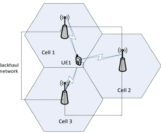
The cell edges are the most challenging area to achieve high data speed in LTE-A. Not only is the signal lower in strength because of the distance from the base station (eNB), but also interference levels from neighboring eNBs are higher [8]. Coordinated multipoint requires coordination between a group of geographically separated eNBs, dynamically coordinate to provide joint scheduling and transmissions and reception. In this way, a user equipment (UE) at the edge of a cell can be served by two or more eNBs to improve signals reception / transmission and increase throughput particularly under cell edge conditions. CoMP techniques falls into two major categories:
Joint processing (JP): Joint processing occurs where there is coordination between multiple entities - base stations - that are simultaneously transmitting or receiving to or from UEs.
Coordinated scheduling or beamforming (CS/CB): CS/CB is a form of coordination where a UE is transmitting with a single transmission or reception point - base station. However, the communication is made with an exchange of control among several coordinated entities.
23
Figure 2.3: Coordinated Multipoint system in JP mode
In JP mode, eNBs share all transmit data and channel state information (CSI) of users through the backhaul links. Multiple BSs transmit data to one user simultaneously on the same frequency [3, 6]. Many CoMP-JP schemes were proposed in literatures. In [35], eNB power constraint and various transmission schemes were discussed. Authors in [36] proposed a block diagonalization method to maximizing the weighted sum-rate of all UEs in the downlink transmission with eNB power constraint. In [37], a cluster constructing strategy was proposed to reduce inter-cluster interference. In JP mode, both the CSI and users’ data have to be shared among the coordinated eNBs, which is only valid for centralized networks.
24
In [38-40], authors proposed various techniques to address the practical issue, such as backhaul limitation, complexity of encoding and decoding. In practice, although coordinated eNBs can exchange information over the backhaul, such as X2-interfaces in LTE-A [41], complete coordination is not achievable due to the backhaul overhead and computational complexity.
Figure 2.4: Coordinated Multipoint system in CS/CB mode
In CS/CB mode, signal for a UE is transmitted from only one single transmission point but the scheduling decision are coordinated among the coordinated eNBs [42, 43]. Transmit beamforming weight of each UE can reduce the interference from each other. CS/CB mode is more practical than JP mode because only partial information needed to be exchanged
25
over backhaul. Precoding matrix index (PMI) reporting algorithm was proposed in [44]. It mitigates the interference based on the report of a restricted or recommended PMI, which can provide a potential precoder at an interfering eNB. The CoMP UEs calculate and report the restricted or recommended PMIs to their serving cell and the PMIs are used as a precoder in interfering eNBs to improve performance. Zero-forcing beamforming was proposed in [45] to compute a new transmit filter based on the CSI feedback from serving and interfering eNBs to force the interference to be zero. In [46], a joint leakage suppression (JLS) filter was discussed by maximizing the signal-to-leakage-plus-noise ratio (SLNR) or the US served by the reference eNB. ZFBF and JLS based CB has more flexibility in system design than PMI reporting algorithm, but requiring more computational complexity, CSI accuracy and backhaul overhead.
26
Chapter 3
Overview of Resource
Allocation for Broadband
Wireless System
In this chapter, the radio resource in wireless communication are described in Section 3.1. Literature reviews on resource allocation and scheduling are presented in Section 3.2. Fuzzy Logic is introduced in Section 3.3.
3.1 Radio Resources in OFDM based
Broadband Wireless Systems
Radio resources are usually referred to carrier frequency resource and transmit power. In multiuser wireless communication systems, channels condition is independent across each user. Channel condition is affected by many factors, i.e. user’s position. Therefore, when the channel is in heavy fading for a user, it may be in a good condition for another user. In this scenario, the system can always choose the user with good channel
27
condition to transmit data to achieve a higher system capacity.
Figure 3.1: Physical resource block
In LTE standard [41], the time-frequency resource is divided into resource blocks. One PRB consists of 12 consecutive subcarriers for one slot. PRB is the smallest element of resource allocation. Allocation of PRBs is handled by a scheduler at the 3GPP eNB. PRB structure is shown in Figure 3.1.
To be detected from attenuation and noise, signals must maintain a certain level of signal power at the receiver. Hence the transmit power should be large enough. Ideally the transmitted power is expected as large as possible. However, this is not realistic in practical. One reason is that when wave form has a high PAPR, transmit power should be low to avoid nonlinear distortion. The other limitation is from standards. To keep
28
network stable, standards usually provide determined transmit power range. Concept of green communication also suggest taking full use of transmit power. It is also an industry requirement [41].
3.2 Resource Allocation in OFDM based
Broadband Wireless System
Since frequency and transmit power management plays vital role in wireless system, resource allocation is essential to utilize frequency diversity and multiuser diversity to enhance system performance
3.2.1
Physical Layer Resource Allocation
OFDM system usually contains a large number of subcarriers, which provide large multiuser diversity in resource allocation [27]. In frequency selective fading channels some subcarriers may be in heavy fading for certain user. However, it is unlikely that all users experience deep fading on the same subcarrier, because the channel characteristics are independent for each user. Therefore, by assigning each subcarrier to the user with the best channel condition on that subcarrier, system performance is enhanced. Many research have been carried out on adaptive RA schemes for OFDM systems to maximize the system sum capacity [47, 48], minimize the sum transmit power [30], guarantee fairness [49] and determine the
29
modulation level order [50]. In [51, 52], low-complexity algorithms that use iterative methods have been presented. Heuristic algorithms such as genetic algorithms (GA) [53] and particle swarm optimization [54] have also been proposed. However, heuristic algorithms are not suitable for real-time application because their performance and complexity depend on many parameters. The aforementioned algorithms don’t adhere to the LTE standard, which require subcarriers to be allocated in blocks.
Considering LTE standard, in [55], three dynamic PRB allocation algorithms were proposed and significantly outperform two-dimensional PRB allocation algorithms. In [56], proposed PRB allocation algorithm ranked users’ utilities with multiple criteria and provides a near optimal performance. Author in [4] proposed an asymmetric resource allocation scheme and achieved optimal system capacity for the downlink wireless multidestination relay system.
In broadband wireless communication systems different frequency normally have different channel characteristics. Hence, uniform power allocation may cause degradations of system performance. In OFDM based wireless communication system, transmit power on each subcarrier can be assign separately [2]. The adaptive power on each subcarrier enhances provides better throughput and robustness of data transmission [57].
30
Figure 3.2: Water-filling algorithm
The water-filling algorithm [58] is the most widely applied power allocation algorithm. Figure 3.2 illustrates the idea of water-filling algorithm. Limited volume of water is poured into a pool with the bottom that has different level. The blue bars represent allocated power 𝑝𝑛 on
each subcarrier. The green parts are determined by channel-to-noise ratio (CNR) 𝛾𝑛. The water-filling problem can be expressed as follow [58]:
31 { 𝑝𝑛 = (𝜀 − 1 𝛾𝑛) + , 𝑓𝑜𝑟 𝑛 = 1, … , 𝐾 ∑ 𝑝𝑛 = 𝑃 𝐾 𝑛=1 , 𝜀 ≥ 0 (3.1)
where (𝑥)+ = max {0, 𝑥}. 𝜀 is the water level chosen to satisfy the power sum constraints. With CSI from UEs, system can find the water level and calculate transmit power for each subcarrier.
3.2.2
Cross-Layer Optimization
With different data streaming services, user has different requirements, which are not related to physical resource of wireless networks. For example, video streaming normally disregards data lag due to buffer mechanism, meanwhile real-time video chatting service highly depends on latency. Since these requirements don’t need extra physical resource, it is possible to satisfy them through cross-layer scheduling. These requirements are described as Quality of Service (QoS). General QoS parameters include data rate, packet loss ratio, and packet head of line (HoL) delay, fairness etc. [59].
Fairness-aware scheduling rules designed for single carrier systems such as proportional fair (PF) [60] , modified largest weighted delay first (M-LWDF) [59], and exponential proportional fair (EXP-PF) [61] can be adapted for OFDMA system by calculating these rules on each resource.
32
M-LWDF takes account of the delay requirement in services and utilizes it with PF to support multiple real-time data users. EXP-PF can support both real-time and non-real-time service and enhance the priority of real-time flows. According to [62] M-LWDF is the best scheduling rule for delay-sensitive applications in term of fairness and efficiency. However, for delay-sensitive traffic, above scheduling rules are not sufficient to avoid delay violation of flows having lower channel quality.
PF assigns resources according to current channel quality and previous throughput of users, which is regarded as very good scheduling algorithm for non-real-time traffic. In [63], authors evaluated the effect of various parameters on the throughput of the PF scheduler through the numerical analysis in CDMA2000 system. Authors in [64] evaluated PF scheduling performance at the flow level and considered a dynamic network setting with random sized service demands. Multiuser scheduler with PF scheduler was proposed in [65] to provides a superior fairness performance with a modest loss in throughput. However, it requires that user average SINRs are uniform, which indicates the importance of RA procedure.
CoMP system faces many challenges in consideration of QoS and overhead and backhaul limitation are two of them. Limit number of CoMP user in cluster is popular method to reduce backhaul data and uplink overhead. In [66] authors addressed joint design of transmit beamformers
33
and user data allocation at BSs to minimize the backhaul data transfer. CoMP user are pre-selected in [67], according to their different QoS requirement. In [9] and [68], distributed user selection and resource allocation are proposed to avoid uplink load.
3.3 Fuzzy Logic
Computer’s logic block usually only understands precise input and produces Boolean logic values TRUE or FALSE, which is equivalent to human’s YES or NO logic. By contrast, humans’ logic often operates in fuzzy evaluations in everyday situation. A decision made by human contains a range of possibilities between YES and NO, including “certainly yes”, “possibly yes”, “hard to say”, “possibly no” and “certainly no” for example. Fuzzy logic (FL) is a method that resembles human reasoning.
Figure 3.3 shows architecture of fuzzy logic systems. Input variables usually take numerical values, which are called “Crisp value” in FL. A fuzzifier module transforms the crisp input into linguistic variables (fuzzy set) by using fuzzy membership function. Membership function quantify linguistic term and represent a fuzzy set graphically. Each crisp value is mapped to a value between 0 to 1, which is called membership value or membership degree [69]. A membership function for a fuzzy set A on the crisp value sets X is defined as:
34
Figure 3.3: Fuzzy logic system architecture
𝜇𝐴: X → [0, 1] (3.2)
Figure 3.4 shows frequently-used fuzzy membership. Their names are recorded in Table 3.1. Normally the choice of membership function depends on empirical experience, or result from comparison of different functions. Researchers also can build their own membership function according to their works [69].
Rules Fuzzifier Defuzzifier Intelligence Crisp Input Crisp Output Fuzzy Input Set Fuzzy Output Set
35
Figure 3.4: Shape of basic membership functions [69] Table 3.1: Membership Function Name [69]
Code Name Membership Function Name
trimf Triangular
trapmf Trapezoidal
gaussmf
Gaussian distribution gauss2mf
gbellmf Generalized bell
sigmf Sigmoidal
zmf Z curve
smf S curve
36
In Figure 3.5, the meanings of the expressions “short”, “medium” and “long” are represented by Trapezoidal membership functions mapping a distance scale. A distance value has three linguistic values according to the three functions. Let’s take a distance with normalized crisp value x=0.45 as example. According to Figure 3.4, this x=0.45 distance may be interpreted as “not long”, “fairly medium” or “kind of short”, with membership degree 0, 0.8, 0.2 respectively.
Figure 3.5: Example of fuzzy membership function
After fuzzification, intelligence engine of fuzzy logic block map fuzzy sets to desired output fuzzy sets by applying IF-THEN rules on each fuzzy value. The operations used for OR and AND are MAX and Min respectively. Combine all results of evaluation to form a final result 𝜇𝐴(𝑥).
37
Defuzzification converts a fuzzy output in to crisp output. The frequently-used defuzzification methods are described below [69]:
Max-Membership Method
This method is limited to peak output functions and also known as height method. This method is the simplest but only useful in special case.
𝜇𝐴(𝑥∗) > 𝜇
𝐴(𝑥) 𝑓𝑜𝑟 𝑎𝑙𝑙 𝑥 ∈ 𝑋 (3.3)
where 𝑥∗is the defuzzified crisp output.
Centroid Method
This mehod is also known as the center of gravity method, which is the most popular and physically appealing of all the defuzzification methods [70]
𝑥∗ = ∫ 𝜇𝐴(𝑥) ∙ 𝑥𝑑𝑥 ∫ 𝜇𝐴(𝑥) ∙ 𝑑𝑥
(3.4)
Weighted Average Method
In this method, each membership function is weighted by its maximum membership value. Valid for symmetrical output membership functions.
𝑥∗ =∑ 𝜇𝐴(𝑥̅ ) ∙ 𝑥𝑖 ̅𝑖
∑ 𝜇𝐴(𝑥̅ )𝑖 (3.5)
where 𝑥̅𝑖 indicates the middle position of membership shape.
Mean-Max Membership Method
This method is also known as the middle of the maxima method.
𝑥∗ = ∑ 𝑥̅𝑖 𝑁 𝑖=1
38
Chapter 4
Resource Allocation for
LTE System with
Coordinated Multipoint
CoMP (Coordinated Multipoint) transmission and reception is introduced in the 3GPP LTE-Advanced standard to enhance system throughput. This technique has been widely studied in recent years because throughput of cellular networks are heavily limited by intercell interference [8]
Power control schemes have been widely investigated to solve CoMP resource allocation problems. In [3, 57, 71], power allocation maximized system throughput with restricted transmit power. Required data rate was applied to be constraints to minimize total transmit power in [6, 66, 72, 73]. In [74], game theoretic method was introduced to solve Quality of Experience (QoE) based power allocation problem. Physical Resource Block (PRB) was randomly allocated in above algorithms. However, PRB allocation strongly affects system throughput [55]. In [75], author proposed
39
to set two fixed groups of PRBs for CoMP and Non-CoMP and perform PRB allocation respectively. In a network with CoMP technique, users are divided into two categories: normal users and CoMP users. As CoMP has influence on system capacity and user fairness, a tradeoff is required in user selection. In [6], backhaul link capacity was considered to establish selection threshold for JP transmission. A zero-force beamforming method was proposed with user selection for CB transmission in [73]. In most literature, channel gain is the major parameter to select transmission mode because it contains effect of both distance and interference condition. In CoMP system, maximum throughput scheduler can maximize the sum throughput of the network but the cell-edge users’ throughput will be extremely low due to their low competitive power. Max-min fairness scheduler improves cell-edge user’s throughput. However, system throughput cannot be guaranteed. Proportional Fairness (PF) algorithm provides a good trade-off between system throughput and cell-edge throughput [76]. Classical PF algorithm is not suitable for CoMP resource allocation.
In this chapter, a Fuzzy Logic (FL) based user selection algorithm is proposed, following with simplified mean enhanced greedy PRBs allocation algorithm, to maximize system capacity, then a ranking based greedy allocation algorithm is proposed to reduce computational complexity. This work is different from existing researches in the following
40
aspects. First, instead of classifying users by single threshold, this work considers three parameters and exploit a fuzzy logic process to categorize users. As a result, measurement errors from single parameter are reduced. Users at edge of threshold are classified more accurate. Second, instead of investigating power control scheme to explore capacity potential, this work improves system capacity by a ranking based PRBs allocation schemes. Simulation results show that proposed fuzzy logic based user selection scheme improves system performance, especially for CoMP users. Proposed ranking based greedy allocation algorithm cut complexity in half but maintain same performance.
Following that, user fairness in CoMP PRBs allocation is investigated and a two-layer proportional-fair user scheduling scheme is proposed. This work is different from existing works in the following aspects. First, fairness between CoMP and Non-CoMP users are focused instead of balancing fairness in each user categories. Second, a modified PF algorithm is proposed to jointly optimize fairness and system capacity. Simulation results show that proposed algorithm significantly improves user fairness.
The rest of this chapter is organized as the follows. Section 4.1 presents the system model. Fuzzy logic based user selection and ranking based PRBs allocation algorithms are presented in Section 4.2. Two-layer proportional-faire user scheduling is presented in Section 4.3. Section 4.4
41
presents the summary.
4.1 System Model
We consider downlink MIMO-OFDMA LTE network with Joint Transmission (JT/JP) CoMP. The CoMP cell cluster is composed of B cells, indicated by ℬ = {1,2, … , 𝑏, … , 𝐵}, serving U user equipment (UE), which are uniformly distributed in coverage area. Furthermore, each transmitter is assumed to have 𝑁𝑡 transmit antennas to support U users with 𝑁𝑟
received antennas per user. CoMP cells can communicate with each other via backhaul link. Frequency reuse factor is 1, number of PRBs is K, and number of subcarriers is M, each PRB is composed of N subcarriers, indicated by 𝑀 = 𝐾𝑁.
The received signal of uth user on the mth subcarrier can be expressed as 𝒀𝑢𝑚 = ∑ 𝑯𝑢𝑚𝑏𝒙𝑢𝑚 𝑏∈ℬ + ∑ ∑ 𝑯𝑣𝑚𝑐𝒙𝑣𝑚𝑐 𝑐≠𝑏 𝑣≠𝑢 + 𝒁𝑢𝑚 (4.1)
The first part of Equation (4.1) indicates desired signal from CoMP cells. For a Non-CoMP UE, its CoMP cells group ℬ only has one serving cell. The second part represents inter-cell interference, where 𝒙𝑢𝑚 is the 𝑙 × 1
42
the 𝑁𝑡× 𝑁𝑟 channel matrix from cell b to user u on subcarrier m. In this
work, each user is equipped with a single receiving antenna. 𝒁𝑢𝑘 is an additive white Gaussian noise (AWGN) with zero mean and variance σ.
The signal to interference and noise ratio (SINR) of uth user on the
mth subcarrier can be expressed as
𝛤𝑢𝑚 = |∑ 𝑯𝑢 𝑚𝑏 𝑏∈ℬ | 2 ∑ |∑𝑐≠𝑏𝑯𝑣𝑚𝑐|2 𝑣≠𝑢 + 𝜎2 (4.2)
Then the date rate of uth user on the mth subcarrier can be expressed as
𝑇𝑢𝑚 = 𝐵𝑊 ∙ log2(1 + 𝛤𝑢𝑚) (4.3)
where BW is bandwidth of subcarrier.
The date rate of uth user on the kth PRB can be expressed as
𝑇𝑢𝑘 = ∑ 𝑇𝑢𝑚 𝑘𝑁
𝑘𝑁−𝑁+1
43
4.2 PRB Allocation with Fuzzy Logic based
User Selection
4.2.1
Problem Formulation
The objective is to allocate PRBs to each user, so that the instantaneous system throughput is maximized. The problem can be expressed as below:
𝑚𝑎𝑥𝑖𝑚𝑖𝑧𝑒: 𝐽𝑐 = ∑ ∑ 𝑇𝑢𝑘 ∙ 𝑆𝑢𝑘 𝐾 𝑘=1 𝑈 𝑢=1 (4.5) Subject to 𝑆𝑢𝑘 ∈ {0,1} (4.6) 𝑆𝑢𝑘 = 𝑆𝑐𝑢𝑘 + 𝑆1𝑢𝑘 + 𝑆2𝑢𝑘 + ⋯ + 𝑆𝑏𝑢𝑘 + ⋯ + 𝑆𝐵𝑢𝑘 (4.7) ∀𝑏 ∈ ℬ: ∑ 𝑆𝑐𝑢𝑘 + 𝑆𝑏𝑢𝑘 𝐾 𝑘=1 = 1 (4.8) ∀𝑏 ∈ ℬ: ∑ 𝑆𝑐𝑢𝑘 + 𝑆𝑏𝑢𝑘 𝑈 𝑢=1 = 1 (4.9) ∀𝑏 ∈ ℬ: ∑ 𝑆𝑏𝑢𝑘 𝑈 𝑢=1 ≤ 1 (4.10) ∀𝑏 ∈ ℬ: ∑ 𝑆𝑏𝑢𝑘 𝐾 𝑘=1 ≤ 1 (4.11)
44
0. When kth PRB is allocated to the uth user is a CoMP user 𝑆𝑐𝑢𝑘 = 1, otherwise 𝑆𝑐𝑢𝑘 = 0. When kth PRB is allocated to the uth user is a Non-CoMP user of cell b, then 𝑆𝑏𝑢𝑘 = 1, otherwise 𝑆𝑏𝑢𝑘 = 0. Equation (4.8)
and (4.9) indicates that PRB occupied by a CoMP user cannot be allocated to any other users. Equation (4.10) and (4.11) describes that in each cell one PRB can only allocated once. From Equation (4.6) - (4.10), though Non-CoMP users don’t affect Non-CoMP users in other cells, PRBs occupied by Non-CoMP user cannot be allocated to CoMP user anymore. In consideration of this constraint, CoMP UEs ℛ𝑐 should be firstly allocated PRBs.
The optimization problem is nonlinear and nonconvex due to the coupled interference among different receivers. With a pre-determined user allocation, the weighted sum rate maximization problem reduces to the conventional sum rate maximization. Weighted sum rate maximization with linear precoding was claimed to be solved by the algorithm in [77]. However, convergence of the optimum solution strongly depends on the initialization. An iterative algorithm based on a repeated transformation from the duel multiple access channel was proposed in [78]. In [79] successive solution of geometric programming problems as proposed. However, aforementioned algorithms only considered a full-coordinated UE group. Resource allocation and fairness balancing among CoMP and Non-CoMP users hadn’t been studied.
45
4.2.2
CoMP User Selection with PRBs Limitation
Cell-edge UE usually receives heavy interference from neighbor cells. Before deploying CoMP to system, it is essential to determine which users are in CoMP mode or Non-CoMP mode. Two threshold based methods are mostly mentioned in literatures: expected SINR based and distance based methods.
With allocated PRBs, the differentiation between CoMP UE and Non-CoMP UE can be made based on the received SINR in Non-Non-CoMP mode at the UE. The mode selection criterion can be expressed as
𝑖𝑓 𝛤𝑛𝑢𝑘 < 𝛤𝑡ℎ𝑟𝑒𝑠ℎ𝑜𝑙𝑑, 𝑢𝑠𝑒𝑟 𝑢 𝑖𝑠 𝑖𝑛 𝐶𝑜𝑀𝑃 𝑚𝑜𝑑𝑒 (4.12)
𝛤𝑡ℎ𝑟𝑒𝑠ℎ𝑜𝑙𝑑 is a predetermined threshold. According to literature [80] it can be set to 3dB. Distance based selection criterion can be expressed similarly as
𝑖𝑓 𝑑̂𝑢 > 𝑑𝑡ℎ𝑟𝑒𝑠ℎ𝑜𝑙𝑑, 𝑢𝑠𝑒𝑟 𝑢 𝑖𝑠 𝑖𝑛 𝐶𝑜𝑀𝑃 𝑚𝑜𝑑𝑒 (4.13)
𝑑𝑡ℎ𝑟𝑒𝑠ℎ𝑜𝑙𝑑can be set to 0.8-0.9 of maximum coverage range of serving cell [9].
The main constraint in user selection is the limited PRB resources. In JT CoMP, a CoMP user occupies same frequency of all cells in the CoMP
46
cluster and this frequency cannot be used by any other users in the cluster, no matter CoMP or Non-CoMP users. When there are a large number of CoMP users, system throughput may increase but many Non-CoMP users have delay due to limited frequency resource. Threshold based user selection method, like Equation (4.12) and (4.13), only divided users into CoMP and Non-CoMP user groups. When number of CoMP user is limited, thresholds must adaptively change.
In addition, cells in same cluster may have different number of Non-CoMP user, which should also be considered in user selection constraint. For a CoMP cluster ℬ = {1,2, … , 𝑏, … , 𝐵}, , number of all users, CoMP users and Non-CoMP users in each CoMP cell are indicated respectively by 𝒰 = {𝑈1, 𝑈2, … , 𝑈𝑏, … , 𝑈𝐵} , 𝒰𝑐 = {𝑈𝑐1, 𝑈𝑐2, … , 𝑈𝑐𝑏, … , 𝑈𝑐𝐵} and
𝒰𝑛 = {𝑈𝑛1, 𝑈𝑛2, … , 𝑈𝑛𝑏, … , 𝑈𝑛𝐵} , where 𝑈𝑏 = 𝑈𝑐𝑏 + 𝑈𝑛𝑏 . To fully exploit PRBs resource of the cluster, maximum total number of CoMP users in the cluster can be expressed as
𝑈𝐶𝑚𝑎𝑥 = 𝐾 − max(𝑈𝑛1, 𝑈𝑛2, … , 𝑈𝑛𝑏, … , 𝑈𝑛𝐵) (4.14)
A ranking based user selection is proposed with constraint of PRBs limitation. According to ranking criterion, users are sorted in order and some top users are chosen as CoMP user according to limited PRB. The algorithms are show in Algorithm 4.1.
Non-47
CoMP PRB SINR 𝛤𝑛𝑢𝑘. It needs to be noticed that 𝛤𝑛𝑢𝑘 is pre-allocated PRB SINR in Non-CoMP mode. Because in this work PRBs will be allocated dynamically, the mean PRB SINR is used instead of pre-allocated PRB SINR, which is given by:
𝑅𝐶𝑢𝛤 = −∑ 𝛤𝑛𝑢 𝑘 𝐾 𝑘=1 𝐾 (4.15)
Algorithm 4.1 Ranking Based CoMP User Selection with Constraint
Initialization: calculate Ranking Criterion 𝑅𝐶𝑢𝛤 for all users in the cluster ℬ =
{1,2, … , 𝑏, … , 𝐵} , number of users in each CoMP cell 𝒰 = {𝑈1, 𝑈2, … , 𝑈𝑏, … , 𝑈𝐵} , number of Non-CoMP users in each CoMP cell 𝒰𝑛 = 𝒰, number of CoMP users in each CoMP cell 𝒰𝑐 = {𝑈𝑐1, 𝑈𝑐2, … , 𝑈𝑐𝑏, … , 𝑈𝑐𝐵} , 𝑤ℎ𝑒𝑟𝑒 𝑈𝑐𝑏 = 𝑈𝑏− 𝑈𝑛𝑏 .
Maximum total number of CoMP users 𝑈𝐶𝑚𝑎𝑥 is set to 0. Data set for uth user is
𝐷𝑖(𝑢, 𝑅𝐶𝑢𝛤, 𝑏, 𝑚𝑜𝑑𝑒), where b is serving cell index of uth user, i is uth user’s ranking
order. The parameter 𝑚𝑜𝑑𝑒 = 0 indicates user is a Non-CoMP user. 1. Rank all data set D in the cluster by descending order of 𝑅𝐶𝑢:
𝑅𝑎𝑛𝑘 = {𝐷1, 𝐷2, … , 𝐷𝑢, … , 𝐷𝑈}, where 𝑅𝐶𝑢𝛤(𝐷𝑖) ≥ 𝑅𝐶𝑢𝛤 (𝐷𝑖+1)
2. From the front to the end of the Rank, set user to be CoMP user one by one, and iteratively check if allocated PRBs overflow:
𝑓𝑜𝑟 𝑖 = 1: 𝑈
𝑖𝑓 𝑈𝐶𝑚𝑎𝑥 < 𝐾 − max(𝑈𝑛1, 𝑈𝑛2, … , 𝑈𝑛𝑏, … , 𝑈𝑛𝐵)
𝑈𝑐𝑏𝐷𝑖 = 𝑈𝑐𝑏𝐷𝑖 + 1; % Update number of CoMP in serving cell 𝑈𝑛𝑏𝐷𝑖 = 𝑈𝑛𝑏𝐷𝑖 − 1; % Update number of Non-CoMP
𝑈𝐶𝑚𝑎𝑥 = ∑{𝒰𝑐}; % Update maximum number of CoMP
𝑚𝑜𝑑𝑒𝐷𝑖 = 1; % Set user to CoMP mode. 𝑒𝑙𝑠𝑒
𝑚𝑜𝑑𝑒𝐷𝑖 = 0; % Set user to Non-CoMP mode. 𝑒𝑛𝑑 𝑖𝑓
𝑒𝑛𝑑 𝑓𝑜𝑟
3. Then the CoMP users set is ℛ𝑐 = {𝑢, 𝑤ℎ𝑒𝑟𝑒 𝑚𝑜𝑑𝑒𝑢 = 1}, Non-CoMP user set
is ℛ𝑛 = {𝑢, 𝑤ℎ𝑒𝑟𝑒 𝑚𝑜𝑑𝑒𝑢 = 0}.
![Figure 2.1: Four types of small-scale fading according to several parameters [19]](https://thumb-us.123doks.com/thumbv2/123dok_us/10176360.2919961/27.892.150.698.503.1040/figure-types-small-scale-fading-according-parameters.webp)