Journal of Unmanned System Technology
Comprehensive Weather Situation Map Based on
XML-Format as Decision Support for UAVs
Martin Köhler†, Franziska Funk‡, Thomas Ger†, Federico Mothes§, and Erwin StenzelϪ †
German Aerospace Center (DLR), Institute for Atmospheric Physics, Oberpfaffenhofen, Germany ‡
Universität der Bundeswehr München, Fakultät für Luft- und Raumfahrttechnik, Institut für Flugsysteme (LRT 13), Germany §
Munich University of Applied Sciences, Germany Ϫ
Airbus Group Innovations, TX2-A, Taufkirchen - Germany Abstract—In the framework of the StraVARIA project
(Autonomy Considerations for Stratospheric High Altitude Pseudo-Satellites made in BAVARIA) a comprehensive weather situation map as decision support for UAVs was newly developed. For this tool, certain weather data (observations, nowcasts, and forecasts) containing information on hazards endangering the mission or the UAV structure itself like thunderstorms, turbulence, wind and cloud cover are combined using a so-called NoGo-Area approach. Using this approach we receive weather objects out of complete data fields which should be avoided by UAVs. All information on the NoGo-Areas, like precise spatial coordinates and time signatures, are stored within a newly developed XML-format. The total of our XML-files, including information on all weather hazards, is seen as the comprehensive weather situation map. It can be used as decision support for UAVs regarding a long-term mission (trajectory) planning and short-term avoidance of weather hazards.
Keywords—XML, weather hazards, UAV, NoGo-Area, autonomous flying.
Copyright © 2017. Published by UNSYSdigital. All rights reserved. DOI: 10.21535/just.v5i1.950
I. INTRODUCTION
TRAROSPHERIC platforms ("High Altitude Pseudo-
Satellites”, HAPS), represent a new class of aircraft that fills the gap between satellites and Unmanned Aerial Vehicles (UAVs). They are characterized by a feature that is best described as “local persistence”. That qualifies them to remain targeted on an area of interest and provide, similar to satellites, communication and earth surveillance services uninterrupted over a long period of time. The ability to perform world record-braking long endurance missions is first since they run solely on solar power. According to that they also save a significant amount of fuel otherwise required by conventional UAVs. Second, they operate at stratospheric altitude and therefore avoid commercial air traffic. Due to these and other advantages too there is strongly growing interest in this type of platforms. Prominent examples of HAPS are the Electric High Altitude Solar Powered Aircraft (ELHASPA) developed by the DLR Institute of Robotics and Mechatronics and the ZEPHYR from Airbus [17][18][27]. Typical missions and use cases of the ZEPHYR, for instances, are maritime and border
surveillance, environmental surveillance, missile detection, navigation, ad-hoc communication bandwidth, continuous imagery and many further.
To accomplish all tasks incurring in a mission currently an extensive service team is required, which is not considered acceptable in future commercial applications. Thus, a correspondingly high level of automation is envisioned for the handling and control of HAPS systems. During critical phases of a mission HAPS will be exposed to a variety of weather hazards. The flight phases include takeoff, ascent, descent and landing. Energy management may require a descent to lower altitudes to preserve battery power. During energy management maneuvers HAPS may come, depending on the operation region, in contact with tropospheric weather phenomena also. Therefore, consideration of weather hazards in trajectory planning is imperative for a save and efficient mission performance.
A first step for weather hazard driven trajectory planning is the automatic detection of weather hazards from relevant sets of weather data. Afterwards, the weather hazards have to be stored in a data exchange format which easily and automatically can be handled by a trajectory planning approach in question. In the frame of the StraVARIA project (Autonomy Considerations for Stratospheric High Altitude Pseudo-Satellites made in BAVARIA) such a format denoted as the StraVARIA weather situation map has been developed. This XML-based format including comprehensive information from various weather data sources will be introduced in the present paper in some detail. The StraVARIA weather situation map continuously is using so-called NoGo-Areas for the description of all types of weather hazards derived from different sets of weather data. This unified and homogeneous approach of describing weather hazards represents the backbone for the application of automatic trajectory planning. Besides our method using XML and NoGo-Areas, other approaches of weather situation maps supporting UAVs have already been developed in the recent years [3][4][5][25].
In Section II, the weather data used for setting up the StraVARIA weather situation map is introduced. Both the data bases and the type of weather hazard extracted from it are presented. In Section III, first general information about the
Corresponding author: Martin Köhler (e-mail:[email protected]) This paper was submitted on May 29, 2017; revised on July 4, 2017; and accepted on August 7, 2017.
Journal of Unmanned System Technology
2XML-format is provided. Afterwards, the different XML products comprising the StraVARIA weather situation map are introduced. Examples of StraVARIA weather situation maps are given in Section IV. One example will deal with a wide-area application and another one with a smaller domain, both requiring different XML components. In Section V, a summary and an outlook regarding the benefits of using a comprehensive weather situation map in the operation of an UAV is given.
II. USED SET OF WEATHER DATA
This section includes an overview of the entire set of weather data used within the weather situation map. All information on the selected weather phenomena, the used data sources and algorithms, and the corresponding forecast horizons can be found in TABLE 1. Altogether four different kinds of weather events including thunderstorms, turbulence, clouds and wind are components of the weather situation map. Since we classify thunderstorms as most dangerous regarding the general safety of UAVs, this weather hazard is overrepresented by four different data sources and algorithms. All information on this pool of weather data is collected as co-called NoGo-Areas (see Section III) and is stored in XML-formatted text files representing our weather situation map. In the following, we give a brief introduction to our used data sources and corresponding algorithms.
A. Thunderstorms/Heavy Precipitation Cells
Rad-TRAM (Radar TRacking And Monitoring) [13], developed at the Institute of Atmospheric Physics at the German Aerospace Center (DLR), allows a reliable detection, tracking and nowcasting (0 – 1 h) of heavy precipitation cells using the European Radar Composite issued by the German Meteorological Service (DWD). This consists of radar reflectivities given in 6-dBZ classes with a horizontal resolution of 2 km × 2 km and encompasses an area of 1800 km × 1800 km [26]. The applied threshold for the detection of the heavy precipitation cells is 37 dBZ. A single heavy precipitation cell must consist of at least 21 contiguous pixels and features therefore a minimum size of 81 km [28]. All information on the detected and nowcasted Rad-TRAM cells is finally stored in XML-formatted files. In Figure 1 you can see a Rad-TRAM example case at 21 May 2009, 1700 UTC.
Cb-TRAM (Cumulonimbus TRacking And Monitoring) [28], also developed at the DLR Institute of Atmospheric Physics, is a fully automated algorithm for the detection, tracking, and nowcasting of intense convective thunderstorm cells (Figure 2) using satellite data from the MSG (Meteosat Second Generation) satellite. Cb-TRAM can identify three different development stages of thunderstorms by combining diverse spectral channels of the SEVIRI (Spinning Enhanced Visible and Infrared Imager [20]) instrument: convective initiation (yellow contours), rapid development (orange contours), and mature thunderstorms (red contours). Equal to Rad-TRAM, the detected cells must consist of at least 21 contiguous pixels [28] and all information is finally stored in XML-formatted files.
The process of converting the radar and satellite raw data into the Rad-TRAM and Cb-TRAM format requires an average runtime of several minutes depending on the current thunderstorm situation.
Figure 1 DWD radar composite (colorful shades) over Southern Bavaria overlaid with detected Rad-TRAM cells (black polygons
at ~ 37 dBZ reflectivity). The grey polygons denote the 1 hour nowcast whereas the black lines represent the recorded tracks of
the Rad-TRAM cells. Source: [11]
Figure 2 Example of a Cb-TRAM plot with yellow polygons representing stage 1 detections (convective initiation), orange polygons are stage 2 detections (rapid development), and red polygons are stage 3 detections (mature thunderstorms). The dotted lines for each object show the 60 minute nowcast. The pink
crosses represent observed flashes which serve as verification of the detected cells. Source: [28]
3
TABLE 1TABLE INCLUDES AN OVERVIEW OF ALL USED WEATHER HAZARDS (LEFT COLUMN), DATA BASES (MIDDLE LEFT COLUMN), ALGORITHMS
(MIDDLE RIGHT COLUMN), AND CORRESPONDING FORECAST HORIZONS (RIGHT COLUMN) WITHIN THE STRAVARIA WEATHER SITUATION MAP
Weather Hazard Data base Algorithm Forecast horizon
Thunderstorms/Heavy precipitation cells Radar data (European Radar Composite) Rad-TRAM 0-1 h
Thunderstorms/Heavy precipitation cells Radar data (OPERA) AWSM 0-1 h
Thunderstorms Satellite data (MSG) Cb-TRAM 0-1 h
Thunderstorms COSMO-DE model Cb-LIKE 1-6 h
3D wind field COSMO-DE model - 1-21 h
Turbulence – Richardson Number COSMO-DE model - 1-21 h
Cloud Cover On-board imaging sensor CCMaps 0-1 h
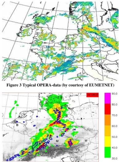
The European Meteorological Network (EUMETNET) runs several programmes related to meteorological observations. One of them is OPERA (Operational Programme for the Exchange of Weather Radar Information) which provides a European platform for exchange of experience in the field of weather radars. In the frame of StraVARIA Airbus Group Innovations (AGI) is using the composite radar product Instantaneous Maximum Reflectivity generated by Odyssey, the OPERA Data Centre, to derive weather objects. To establish a weather radar (WxR) data base AGI procured historic OPERA data from the German Weather Service (DWD) and Meteo France. Alternatively, OPERA licenses are available to access data in near real-time (FTP via Internet, VPN). The domain of OPERA is whole of Europe, as illustrated in Figure 3, and the spatial resolution of data is 2×2 km.
AGI is using segmentation and other image processing techniques to derive weather objects (NoGo-Areas) described as 2D polygons from OPERA data. The segmentation process is threshold driven. The weather objects and additional final information are strored in XML-formatted files. The XML format conceived at AGI (AGI Situation Map – AWSM) depends on aircraft position and flight direction and computes the weather objects in a local frame similar to the plan position indicator provided by typical airborne radar systems. Use of this format is illustrated in combination with cloud detection in Section IV.E. Matlab code for generation of AWSM was profiled. In executing several hundred weather scenarios, a mean runtime of 2 seconds resulted for a map size of about 100000 square kilometers. Code is not optimized and significantly better performance can be expected for C/C++ implementations.
By using both radar and satellite data, we receive vertical information on the observed heavy precipitation cells/thunderstorms. The radar data covers the lower atmospheric levels whereas the satellite data encompasses the upper troposphere/lower stratosphere.
Cb-LIKE (Cumulonimbus-LIKElihood) [14] provides long-term thunderstorm forecasts for a prognosis horizon up to six hours. It is an automated system which designates areas with possible thunderstorm development by using COSMO-DE model data. This model, operationally driven by the German Meteorological Service (DWD), is non-hydrostatic featuring a resolution of 2.8 km [19], and provides forecasts up to 21 hours with a 3-hour update rate between 0000 and 2100 UTC. Its
domain covers Germany and parts of the neighboring countries. Within Europe, it possesses one of the highest resolutions and features, therefore it provides a full calculation of large convective phenomena (no parameterization of deep convection) [1]. Cb-LIKE itself uses an innovative fuzzy-logic system for the combination of model data and the subsequent calculation of a thunderstorm indicator from 0 up to 100 for each grid point of the COSMO-DE model domain. The higher the indicator the more likely will thunderstorms occur.
Figure 3 Typical OPERA-data (by courtesy of EUMETNET)
Figure 4 Example of a four hour Cb-LIKE forecast for 1600 UTC (22 June 2011) using the COSMO-DE model run from 1200 UTC. The Cb-LIKE prognoses are displayed as colored surfaces. The blue contour lines represent heavy precipitation cells observed by Rad-TRAM at 1600 UTC and serve therefore as verification of the
Journal of Unmanned System Technology
4Applying a certain thunderstorm indicator as threshold, we can define Cb-LIKE thunderstorm objects which are finally stored in XML-formatted files. These objects can then be used as NoGo-Areas. Figure 4 shows a four hour Cb-LIKE forecast for Middle Europe. The forecasts are displayed as colored surfaces whereas the blue contour lines represent the observed heavy precipitation cells by Rad-TRAM which serves therefore as verification.
The transformation process of the COSMO-DE model data into the Cb-LIKE output format requires a mean runtime of about five minutes referring to the whole COSMO-DE model domain. In case of smaller domains like Germany, the processing time is becoming less than one minute.
B. Turbulence – Richardson Number
According to [23], the Richardson number (Ri) and its single components are well-known turbulence diagnostics (see also [9], [15], and [6]). Theory and observations have both shown that in certain situations clear-air-turbulence pattern are produced by so-called Kelvin-Helmholtz instabilities. These occur in cases when Ri becomes small. Values in the range 10 to 0.1 are thereby typical, with values below unity indicating significant turbulence. The lower the value the higher the expected degree of turbulence is. This is in particular valid for Ri values of 0.25 or less [6]. A value of 0.25 is thereby known as “critical Richardson number”. Other sources, e.g. [16], classify the critical Richardson number in a value range between 0.2 and 0.5. In aviation, it is used as a rough measure of expected air turbulence. Ri is also part of state-of-the-art turbulence forecasting algorithms, see for example the Graphical Turbulence Guidance (GTG) [23]. It is a dimensionless quantity and can be calculated by:
1 2 2 1 z v z u z g Ri
(1)where Ri represents the ratio of vertical stability to wind shear squared, g is the gravity, θ is potential temperature, z is height, and u and v are the horizontal wind components, respectively. In case of the StraVARIA project, we use the COSMO-DE model data for calculating the Richardson number for every grid point of the model domain. The converting process of the COSMO-DE model data into the Ri field requires a runtime of less than one minute. For the provision of 3D information, we interpolate Ri also on the standard flight levels. According to the performance of the COSMO-DE model, we can provide a Richardson number forecast up to 21 hours.
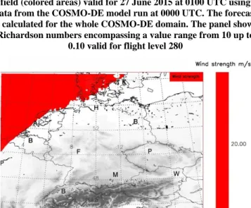
Figure 5 shows an example of a Richardson number forecast for the complete COSMO-DE model domain at 27 June 2015 0100 UTC. The prognosis is valid for flight level 280. By selecting a certain value, we can define Richardson number objects which can subsequently be used as NoGo-Areas. All information on these objects is also stored within XML-formatted files.
C. 3D Wind Field
The 3D wind field is directly taken from the COSMO-DE model output and therefore also available for a forecast horizon of 21 hours. Therefore, there is no significant data converting process requiring a certain time span. At each grid point of its domain, the model provides a complete wind vector V including both horizontal and vertical components [1]. The information is thereby stored in every vertical model layer. Again, we interpolated the wind vectors on the standard flight levels.
As next step, we calculated the wind strength in m/s at every grid point and height level. By selecting a certain wind strength as threshold, we defined so-called “wind-objects” out of the vector field. These objects are then used as the NoGo-Areas for the StraVARIA weather situation map. Figure 6 shows an example of a 1-hour forecast of a “wind object” using the threshold of 20 m/s on flight level 240. As it can be seen, the top left corner of the COSMO-DE model domain features a large area including wind strengths of 20 m/s and higher.
Figure 5 The figure shows a 1-hour Richardson number forecast field (colored areas) valid for 27 June 2015 at 0100 UTC using data from the COSMO-DE model run at 0000 UTC. The forecast is calculated for the whole COSMO-DE domain. The panel shows Richardson numbers encompassing a value range from 10 up to
0.10 valid for flight level 280
Figure 6 The figure shows a 1 hour forecast of “wind objects” (red areas) valid for 10 August 2015 at 0100 UTC. The corresponding wind data is taken from the COSMO-DE model run at 0000 UTC. The applied threshold for defining the objects is 20 m/s. The wind
5 D. Cloud Cover
Cloud data is acquired by an onboard sensor on the UAV itself. In contrast to a weather radar, which is emulated in this project based on OPERA-data, this information is based on a passive imaging sensor system. It was especially designed at the University of the Bundeswehr Munich for operation on lightweight UAV, which are highly restricted regarding mass and energy consumption [12]. This sensor system also allows for detection of all cloud types instead of only thunderstorms or heavy precipitation cells.
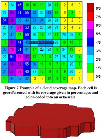
The detected cloud cover is described by both large-scale cloud coverage and high-resolution cloud object information. At first the gimbal controlled sensor allows a scan of the surroundings in all horizontal directions around the UAV. While individual cloud objects can be obscured due to the observation angle, an upper boundary of cloud coverages in defined cells is estimated. These cells are horizontally georeferenced and describe either the total cloud coverage above or beneath the UAV. This coverage map is illustrated in Figure 7 together with the UAV position at the start of data acquisition. Typically, each cell covers 10×10 km2 and the coverage values are given in percentages.
Figure 7 Example of a cloud coverage map. Each cell is georeferenced with its coverage given in percentages and
color-coded into an octa-scale
Figure 8 Example of a single cloud object, which is part of a cloud map. Each vertex is given in precise spatial coordinates
Additionally, positions and dimensions of each individual cloud object are detected during the second mode of operation directly beneath or above the UAV. This so-called cloud map is obtained utilizing the UAV movement for position triangulation. Precise cloud position and dimension
information is obtained in horizontal dimension and for the side of the cloud facing the sensor. In the case of this high-flying UAV the base of clouds detected underneath can only be approximated. In Figure 8 a single 3D cloud object is shown. The two maps of cloud coverage and single objects are stored in XML-formatted files describing the cloud cover.
This onboard cloud detection system directly produces cloud cover XML-files as output, so that no conversion is necessary in order to integrate the data into the weather situation map. These results are produced in real time in the case of the cloud coverage map, while the cloud map calculation is more limited by the speed of the UAV. Examples of both maps can be seen in section IV.E.
III. XML-FORMAT AND NOGO-AREAS
This section provides a general introduction of the XML-format describing its main advantages. Secondly, the StraVARIA XML products are presented.
A. General information on XML
XML (eXtensible Markup Language) was developed and introduced by W3C [24] and has evolved into a standard and widespread language applied for the encoding of documents that should be readable by both human and machine. This language is commonly used to display hierarchically structured data in text file format. These documents can be easily produced and read using widespread software. Hence, certain problems like expandability, international exchange, and platform dependency can be avoided. The most important part of an XML structure always includes data describing tags. These tags are not predefined and must therefore be defined by the corresponding creator. Hence, the XML format was created to structure, store and send information but it does not define what is needed to be done with the stored data; it is just pure information wrapped in the XML tags [2]. It serves therefore as an interface providing a platform for independent data interchange between different and often incompatible computer systems. For more information, please have a look at [7] and [8].
In the framework of the project StraVARIA, we decided to use the XML format due to its possibility of an unproblematic data interchange between all project partners regarding the different weather data which stems originally from different algorithms and software. All data described in the previous section are stored within XML text files featuring a similar structure, respectively. This structure was in parts newly designed in the framework of StraVARIA and enables a fast processing (combination, visualization) of all weather data. The total of all StraVARIA XML-files is defined as our comprehensive weather situation map.
In general, the application of the XML format brings along one more interesting advantage regarding our purposes. In our case, a common XML file features only a minor size of several megabyte due to the selective storage of weather information as NoGo-Areas instead of applying whole data fields as described in the previous section. This could be very useful regarding a possible weather data link between UAVs and corresponding
Journal of Unmanned System Technology
6ground stations during possible future missions. For example, the radar data used as input for the Rad-TRAM algorithm features a common size of several gigabyte whereas the Rad-TRAM XML files normally possess a maximum size of about ten megabyte dependent on the general thunderstorm situation. A single Rad-TRAM object features only a size of few kilobyte.
Finally, the XML format is becoming a standard of data exchange in the current European and US-American air traffic management renewal programs SESAR [22] and NextGen [10].
B. NoGo-Areas as data information stored in StraVARIA XML As described in section II, so-called NoGo-Areas can be defined out of weather data fields using certain thresholds such as dBZ in case of the radar data (e.g. 37 dBZ for Rad-TRAM or m/s in case of the COSMO-DE wind data). In general, a NoGo-Area denotes a zone which should be avoided by UAVs. These zones could contain disturbing or hazardous weather phenomena (e.g. clouds, thunderstorms or turbulence) endangering the UAV mission or the vehicle structure itself. We apply this kind of NoGo-Areas in the framework of our weather situation map because they represent a distinct weather information to be used for pilots or trajectory planning algorithms. In this context, distinct weather information means that a NoGo-Area does not have to be further interpreted in a meteorological sense. Hence, they are very suitable for an automatic detection and handling by pilots or trajectory planning approaches.
C. Overview of the structure StraVARIA XML products In the following, we want to give a short overview of the StraVARIA XML products applied for our weather situation map. These can be divided into two classes: static and dynamic XML-files. Static XML-files include the information on all NoGo-Areas valid for a certain point of time within a defined geographic domain. Out of these files, a trajectory planning algorithm can automatically consider the specific NoGo-Areas needed for planning a certain flight route around these areas. On the other hand, the dynamic XMLs are permanently recalculated and produced depending on the current position of a UAV. These files contain only information on NoGo-Areas detected by the UAV itself. In general, the static XML-files serve rather for a long-range mission (trajectory) planning whereas the dynamic XMLs can be used for a short-term avoidance of weather hazards endangering the mission or the UAV structure itself. The static XMLs include the thunderstorm nowcasting products: Cb-TRAM and Rad-TRAM, plus the thunderstorm forecasting products: Cb-LIKE, the Richardson number and the 3D-Wind information. The NoGo-Areas obtained from the radar emulation (OPERA-data) and the in-situ cloud detection are thereby stored within the dynamic XML-files.
Apart from the classification and the different forecast horizons, the XML-files of each data source feature a very similar structure. The structure itself stems originally from the algorithms Cb-TRAM and Rad-TRAM. This ensures an
enormous simplification regarding the general data processing within the project. As every XML, the StraVARIA XML-structure consists of meta and object data. The meta data includes general information on the style and content of the respective file itself. In contrast, the object data encompasses all necessary information on the individual NoGo-Areas concerning, among others, precise spatial coordinates and time signatures which are the basic requirements for an application within a trajectory planning algorithm. An overview of the most important stored information wrapped by our defined tags can be found in TABLE 2.
TABLE 2OVERVIEW OF THE MAIN STRAVARIAXML TAGS
Tag Description Data
Time Date of observation All
Covered
Area Observed region All
Tracking
ID ID of tracked object All
Confidence
Level Quality of observed data All Threshold Threshold
for object definition
All except Cloud Cover Max Values Max values within the object
All except Cloud Cover Gravity Center Gravity center
of detected objects All Polygon Latitude/longitude
coordinates of object All UAV
Position Current position of UAV
Only Cloud Cover and OPERA data Sensor
parameters
Sensor settings for
Cloud Cover detection Only Cloud Cover
IV. GRAPHICAL EXAMPLES OF THE WEATHER SITUATION MAP
In the following, we want to present certain graphical examples regarding the NoGo-Areas and the weather situation map in order to show the general benefit of the StraVARIA weather products. Figure 9 to Figure 12 show partially the weather situation over the region of Bavaria (MUC = Munich Airport) at 27 June 2015 1900 UTC plus three hour forecasts. All NoGo-Areas are read-in from our XML-files. On all four figures the Rad-TRAM observations are plotted as orientation regarding the current thunderstorm situation. In addition, Figure 13 and Figure 14 present an example of the on-board data (cloud cover, OPERA radar data) while Figure 15 and Figure 16 show our two test-cases.
A. Example 1: Rad-TRAM
In Figure 9, the dark blue objects represent the observed Rad-TRAM observations at 1900 UTC whereas the light blur dashed color lines denote the one hour nowcast. It should be now obvious that our NoGo-Area approach is well suitable for
7 an autonomous flying of UAVs. The blue NoGo-Areas (observations as well as nowcast) represent a simple weather information which is not needed to be further interpreted and can therefore easily processed using a trajectory planning algorithm. This is valid for fast evasion manoeuvers regarding the observations, and also for a short-term trajectory planning using the corresponding nowcasts. In general, the application of this information should lead to a higher safety regarding the mission operation and the UAV itself.
Figure 9 Rad-TRAM observations (blue contours) and one hours nowcasts (light blue dashed lines) over the Region of Bavaria at 27
June 2015, 1900 UTC
Figure 10 Rad-TRAM observations (blue contours) and three hour Cb-LIKE forecasts (orange contours) over the Region of Bavaria at 27 June 2015, 1900 UTC. The Cb-LIKE forecasts are
valid for 2200 UTC
B. Example 2: Rad-TRAM And Cb-LIKE
In Figure 10, besides the Rad-TRAM observations (blue contours) at 1900 UT, the three-hour Cb-LIKE forecasts valid for 2200 UTC (orange contours) are displayed. As it can be seen, Cb-LIKE predicts an Eastern shift of the 1900 UTC observed thunderstorm activity. Therefore, the occurrence of thunderstorms is expected for Middle Bavaria (N = Nuremberg) and over the Czech Republic (the area north-east of Regensburg (R) and Passau (P)) at 2200 UTC. Applying this kind of thunderstorm forecast information enables pilots or trajectory planning algorithms a sensible mission planning regarding long-term time horizons. Using the NoGo-Areas issued by Cb-LIKE, an automatic avoidance of areas where strong thunderstorms will very likely occur in the next few hours is now possible.
C. Example 3: Rad-TRAM And Wind Strength
Figure 11 shows, besides the Rad-TRAM observations for 1900 UTC, the NoGo-Areas extracted from the 3D wind field (pink contour lines). In this example, they base on a threshold of 25 m/s and are interpolated on flight level 250. The wind NoGo-Areas represent the three hour forecast and are therefore valid for 2200 UTC. Applying the StraVARIA wind information in general, a pilot as well as a trajectory planning approach knows the altitude and strength of the future wind. This information can then be easily used within a long-term mission planning. Let’s assume, in the present case example, an observing mission has to be run in the eastern part of the domain illustrated in Figure 11 but the forecasted wind strength in form of our NoGo-Areas endangers the general structure of the UAV itself. By using this wind information, the mission can be easily rescheduled leading again to more safety regarding the mission operation.
Figure 11 Rad-TRAM observations (blue contours) and three hour wind forecasts (pink contours) over the Region of Bavaria at
27 June 2015, 1900 UTC. The wind forecasts are valid for 2200 UTC. The applied threshold for the wind NoGo-Areas is 25 m/s
and they are interpolated on flight level 250
Figure 12 Rad-TRAM observations (blue contours) and three hour Richardson Number forecasts (purple contours) over the Region of Bavaria at 27 June 2015, 1900 UTC. The forecasts are
valid for 2200 UTC. The applied threshold for the Richardson Number NoGo-Areas is 2 and they are interpolated on flight level
Journal of Unmanned System Technology
8D. Example 4: Rad-TRAM And Richardson Number
Figure 12 shows, besides the Rad-TRAM observations at 1900 UTC, the Richardson Number NoGo-Areas (purple contour lines). The NoGo-Areas (threshold ≤ 2) are interpolated on flight level 120 and valid for 2200 UTC (three hour forecast). A fictive case example including an UAV landing process should illustrate the general advantage applying the Richardson Number NoGo-Areas. We assume that a landing is planned at approximately 2200 UTC and the landing site is located within the triangle of Munich (M), Augsburg (A) and Hohenpeissenberg (HP) (see Figure 12). Using the Richardson Number NoGo-Areas for this time and location, a pilot as well as trajectory planning algorithm would have the information on strong turbulences that may occur and be dangerous for the UAV itself. This could lead to a temporal or spatial displacement of the landing process or landing site in our fictive example.
Figure 13 Cloud coverage (blue squares) detected by the UAV and observed heavy precipitation cells (red contours) out of the OPERA based data (AWSM algorithm) over Bavaria at 27 June
2015, 1700 UTC. The current UAV position is marked with a yellow dot. The OPERA heavy precipitation cells are obtained by
using a threshold of 37 dBZ while the cloud coverage is detected using a passive imaging sensor system
E. Example 5: OPERA Data And Cloud Cover
Figure 13 shows the NoGo-Areas out of the OPERA radar data (red contours, threshold = 37 dBZ) and the cloud coverage NoGo-Areas (detected by the UAV itself) illustrated as blue squares over West-Bavaria. The weather data in this example is valid for 27 June 2015 at 1700 UTC. The current position of the UAV in the east of Stuttgart is marked with a yellow dot. The lower the transparency of the blue colors of the cloud coverage squares, the higher is the general cloud coverage in the corresponding area. In Figure 13, only weather information detected by the UAV itself (imaging sensors = cloud detection, radar = heavy precipitation cells/thunderstorms) stored in the dynamic XMLs are plotted.
Figure 14 An enlarged section of Figure 11 around the UAV (yellow spot) is shown. The blue squares represent the cloud coverage, the blue filled objects the detected clouds. The data is
valid for 27 June 2015, 1700 UTC
Figure 14 displays an enlarged section of Figure 13 around the UAV marked again with a yellow dot. The blue squares serving as cloud cover NoGo-Areas according to their transparency factor are now very easy to recognize. The blue-filled objects represent the single clouds which are also detected by the UAV and are part of the so-called cloud map. It should be now obvious that this kind of information is also very suitable especially for the short-term mission planning. The detected cloud coverage can be applied to analyze the areas in the vicinity of the UAV itself which may be used for a surveillance mission. The higher the cloud coverage the worse the performance of a surveillance mission is. Hence, this kind of information could be used for an optimal mission planning by pilots or algorithms. It increases also the general safety level regarding an UAV ascent/descent at the beginning/end of each mission avoiding areas with high cloud coverages. This is especially valid for the thunderstorms/heavy precipitation cells detected by the UAV, here illustrated by the OPERA data, and the single cloud objects. Applying this data, a pilot or an algorithm can initiate short-term evasion manoeuvers.
F. Example 6: GUI and Test Case
The Figure 15 and Figure 16 show two possible application examples of the StraVARIA weather situation map. Both graphics were produced by the StraVARIA partner at the University of Applied Sciences Munich. Figure 15 illustrates an example of a Graphical User Interface (GUI) displaying all NoGo-Areas stored in the StraVARIA XML-files. In this case, only the Cb-TRAM/Rad-TRAM NoGo-Areas (red objects) together with their corresponding direction vectors are plotted. In general, a GUI like this is a very suitable tool for rendering the complete weather situation map simultaneously on one screen. By plotting the original UAV flight route (blue line) and the optimized route (green line) regarding the Cb-TRAM and
J Unmanned Sys Tech, 2017, Vol. 5, No. 1
9
Figure 15 On this GUI the complete StraVARIA weather situation map can be displayed. In this case, only the Cb-TRAM and Rad-TRAM NoGo-Areas (red objects) plus the belonging directional vectors are plotted. The blue line denotes the original UAV flight
pass, the green line the optimized route avoiding the time-variant NoGo-Areas
Figure 16 On this fictional test case example, a UAV flight route is planed regarding the StraVARIA NoGo-Areas. The UAV is marked with a little plane. The UAV has to avoid the No-Go-Areas within the domain. A flightpath is calculated from the “Current Position”.
The three figures show the UAV position at different times (t1, t2, t3 from left to right)
Rad-TRAM NoGo-Areas, the large benefit of our weather situation map can be easily seen. For the future, such GUI could be used as survey map by operators at ground station and could serve as neat planning tool for long-term UAV missions.
Figure 16 shows exemplarily a possible autonomous evasion maneuver regarding fictive StraVARIA NoGo-Areas using a trajectory planning algorithm. The red frame denotes the operation area, the UAV (illustrated as small plane) must
reach the “Destination” starting at the “Current Position”. The colored objects represent exemplarily heavy precipitation cells stored as NoGo-Areas in our XML-files. The cells are thereby not static but moving from left to the right following a certain wind field. Different time steps (t1 (left), t2 (middle) and t3 (right)) are displayed. At the first-time step (t1), the direct way between destination and UAV position is blocked by the three NoGo-Areas. Hence, a trajectory planning algorithm has to calculate an alternative but optimal route while avoiding the
Journal of Unmanned System Technology
10heavy precipitation cells. The result can be seen in the middle figure at t2. The algorithm found an optimal way avoiding the objects instead of sending the UAV around the weather hazards which would be safe but not optimized regarding time and energy capacities. This represents the optimal flight route regarding time and safety issues. In the right figure (t3), the UAV has left the NoGo-Areas behind and can reach the destination without any further problems.
In this fictional example, it can be very easily seen, that the NoGo-Areas of the StraVARIA weather situation map are very suitable within the mission and trajectory planning of an UAV. No further meteorological interpretation of the data is necessary, an algorithm or pilot only has to avoid the objects themselves. In contrast of using normal weather data, this is an enormous simplification regarding the development of such an algorithm. As it has been shown in Figure 15 and 16, the StraVARIA NoGo-Areas can be used simultaneously for a long-term mission planning (Figure 15) as well as short-term evasion maneuvers (Figure 16). This should lead to a higher degree of autonomy regarding UAVs.
V. CONCLUSIONS
In the framework of the project StraVARIA, we developed a comprehensive weather situation map. This new tool includes information (observation and forecast) on certain weather situations like thunderstorms, turbulence, 3D wind, and cloud cover that may pose a hazard to UAV’s and general aviation. We also defined a new XML-format for a sensible storing of the weather data regarding interchangeability, readability and memory consumption. By using this format, weather data from different sources and algorithms can be converted into the same (XML) format which is very useful regarding large projects like StraVARIA including many partners and users. The ensemble of all XMLs is then called the StraVARIA weather situation map.
The main advantage of the developed weather situation map represents the selective storage of information on the weather data. That means that not the complete radar, turbulence, cloud or wind field is saved within the XML-files but only so-called NoGo-Areas. These objects are obtained by applying certain thresholds (e.g. 37 dBZ for the radar field or 25 m/s for the wind field) on the origin data fields. A large benefit of the NoGo-Areas is that they do not have to be further interpreted in a meteorological sense. Their message for pilots or trajectory planning algorithms is already in the name. Hence, these NoGo-Areas are very suitable to be applied in the framework of long-term mission planning as well as short-term evasion manoeuvers of UAVs. Summarized, our newly developed weather situation map including the NoGo-Area concept makes an important contribution to a future higher degree of autonomy regarding UAVs. Hazardous weather is in general dangerous for the mission operation but also for the UAV structure itself. Using the information on the NoGo-Areas, the severe weather can be (automatically) avoided leading to a higher safety regarding the mission operation and the UAVs itself.
Two fictive case examples showing the positive impacts of the newly developed weather situation map on the long-term mission planning as well as short-term evasion manoeuvers are also presented in the paper. Currently, its positive effects on the general autonomy of UVAs is tested in the framework of a comprehensive simulation. An important task to be done in the near future should be the application of the StraVARIA weather situation map in the framework of a real UAV mission. Further future tasks could be the implementation of additional weather parameters like fog within the weather situation map. These parameters could be obtained from numerical weather models, but also be observations collected by ground stations. This is very important regarding the start as well as the landing phase of a UAV. Both are the most critical mission phases. High resolution weather data (observations as well as forecasts) in time and space for the start, cruise and landing site are essential for safe UAV missions.
ACKNOWLEDGMENT
The authors of this work gratefully acknowledge the State of Bavaria for funding the StraVARIA project in the frame of the Luftfahrtforschungsprogram (Förderkennzeichen: LABAY82A, LABAY82B, LABAY82C, LABAY82D). The authors also gratefully acknowledge the Ludwig Bölkow Campus in Munich where the work has been conducted. Furthermore, we would like to thank EUMETNET for supporting the use of OPERA-data and the German Meteorological Service providing the COSMO-DE model data.
REFERENCES
[1] Baldauf M., Förster J., Klink S., Reinhardt T., Schraff C., Seifert A. and Stephan K, “Kurze Beschreibung des Lokal-Modells Kürzestfrist COSMO-DE (LMK) und seiner Datenbanken auf dem Datenserver des DWD“. Stand 31.03.2011, Deutscher Wetterdienst, Geschäftsbereich Forschung und Entwicklung, Postfach 100465, D-63004 Offenbach, 2011.63004 Offenbach, 2010.
[2] Besprozvannykh A. V., “Extensible Markup Languagen(XML): Essentials for Climatologists, “CCI OPAG 1 Implementation/ Coordination Team, 2005)
[3] Bottyán Z., Gyöngyösi A. Z., Wantuch F., Tuba Z., Kurunczi R., Kardos P., Istenes Z., Weidinger T., Hadobács K., Szabó Z., Balczó M., Varga A., Kircsi A. B. and Horvath G., “Measuring and modeling of hazardous weather phenomea to aviation using the Hungarian Unmanned Meteorological Aircraft System (HUMAS),” Időjárás. vol. 119, no. 3, pp. 307-335, 2015.
[4] Bottyán, Z., Wantuch, F. and Gyöngyösi, Z., “Forecasting of Hazardous Weather Phenomena in a Complex Meteorological Support System for UAVs,” J Unmanned Sys Tech, vol. 2, no. 2, pp. 79-86, 2014.
[5] Bottyán, Z., Wantuch, F., Gyöngyösi, Z., Tuba, Z., Hadobács, K., Kardos, P. and Kurunczi, R., “Development of a Complex Meteorological Support System for UAVs”, World Academy of Science Engineering and Technology, Vol. 76, 2013, pp. 1124, 1129.
[6] Dutton, J. and Panofsky, H. A., “Clear air turbulence: A mystery may be unfolding,” Science, vol. 167, 937-944, 1970. CrossRef
[7] Elliotte Rusty Harold & W. Scott Means, XML in a nutshell, O’Reilly Verlag 2011
[8] Elliotte Rusty Harold, XML Bible, IDG Books Worldwide, Inc. 1999 [9] Endlich, R. M., “The Mesoscale Structure of Some Regions of Clear-Air
Turbulence”, J. Appl. Meteor., vol. 3, pp. 261 – 276, 1964. CrossRef
11
[11] Forster C. and Tafferner A., “Nowcasting Thunderstorms for Munich Airport”. DLR-Forschungsbericht, Projektbericht. DLR-FB–2012-02, 14 S. Deutsches Zentrum für Luft- und Raumfahrt e.V., Bibliotheks- und Informationswesen, Köln, 2012.
[12] Funk, F. and Stütz, P., “A Passive Cloud Detection System for UAV: Weather Situation Mapping with Imaging Sensors,“ IEEE Aerospace Conference Proceedings, 2017. CrossRef
[13] Kober K. and Tafferner A., “Tracking and nowcating of convective cells using remote sensing data from radar and satellite,” Meteorologische Zeitschrift, vol. 18, no. 1, pp. 75-84, 2009. CrossRef
[14] Köhler M., Tafferner A. and Gerz T., “Cb-LIKE – Cumulonimbus LIKElihood: Thunderstorm forecasting with fuzzy logic,” Meteorologische Zeitschrift, vol. 12, 2016.
[15] Kronebach, G. W., ‘An automated procedure for forecasting clear-air turbulence,” J. Appl. Meteor., vol. 3, pp. 119-125, 1964. CrossRef
[16] Lyons, R. and Panofsky, H. A. and Wollaston, S., “The Critical Richardson Number and Its Implications for Forecast Problems,” J. Appl. Meteor., vol. 3, pp. 136 – 142, 1964. CrossRef
[17] Marsh G., “Best endurance under the sun, “ Renewable energy focus, vol. 11, issue 5, pp. 24-27, 2010
[18] Mehta A., Yadav S., Solanki K. and Joshi C., “Solar Aircraft: Future need,” International Journal of Advanced Engineering Technology,”, vol 3, issue 4, pp. 43-48, 2012
[19] Schättler U., Doms G. and Schraff C..,”A Description of the
Nonhydrostatic Regional COSMO-Model,” Printed at
DeutscherWetterdienst, P.O. Box 100465, 63004 Offenbach, Germany, 2013.
[20] Schmid, J. “The SEVIRI instrument,” Proceedings of the 2000 EUMETSAT Meteorological Satellite Data Users`Conference, Bolgona, Italy, May 29 June 2, 2000, pp. 23-32.
[21] Schulz, J. P. and Schättler, U., ”Kurze Beschreibung des Lokal-Modells Europa COSMO-EU (LME) und seiner Datenbanken auf dem Datenserver des DWD,“ Stand 20.05.2010, Deutscher Wetterdienst, Geschäftsbereich Forschung und Entwicklung, Postfach 100465, D 63004 Offenbach, 2010.
[22] SESAR: https://www.sesarju.eu/
[23] Sharman, R., Tebaldi, C., Wiener, G. and Wolff, J., “An integrated approach to Mid- und Upper-Level Turbulence Forecasting,” Wea. Forecasting, vol. 21, pp. 268 – 287, 2006. CrossRef
[24] W3C, XML: http://www.w3c.org/XML/
[25] Wantuch, F., Bottyán, Z., Tuba, Z. and Hadobács, K., “Statistical methods and weather based decision making in meteorological support for Unmanned Aerial Vehicles (UAVs)”, IEEE International Conference on Unmanned Aircraft Systems, IEEE Xplore, Atlanta, GA, USA, 2013, pp. 203–207. CrossRef
[26] Weigl E., Klink S., Kohler O., Reich T., Rosenow W., Lang P., Podlasly C., Winterrath T., Majewski D. and Lang J., “Abschlussbericht Projekt RADVOROP: Radargestuetze, zeitnahe Niederschlagsvorhersage fuer den operationellen Einsatz (Niederschlag-Nowcasting-System),“ Technical report, Deutscher Wetterdienst Abteilung Hydrometeorologie, 2005.
[27] Zhu X., Guo Z. and Hou, Z., “Solar-powered airplanes: A historical perspective and future challenges,“ Progress in Aerospace Sciences, vol. 71, pp. 36-53, 2014. CrossRef
[28] Zinner T., Mannstein H. and Tafferner A., “Cb-TRAM: Tracking and monitoring severe convection from onset over rapid development to mature phase using multi-channel Meteosat-8 SEVIRI data,“ Meteorol. Atmos. Phys., vol. 101, pp. 191-201, 2008. CrossRef