B.Sc Engineering Thesis Paper
On
“
Designing and Interfacing a Hospital-Based
Database System
”
(A Case Study of BIRDEM)
Department of
Computer Science & Engineering
Ahsanullah University of Science & Technology
Dhaka, Bangladesh.
A thesis paper submitted in partial fulfillment of the requirements
for the Degree of B.Sc Engineering (Computer Science &
Engineering)
Date: - July 12, 2010
Session: - Spring ’10
“Designing and Interfacing a Hospital-Based
Database System”
(A Case Study of BIRDEM)
Submitted By:-
1. Syed Mahboob Nur
06.02.04.013
2. Jahid Hasan
06.02.04.036
3. Kazi Sumaiya
06.02.04.042
4. Tasfia Rahman
06.02.04.044
In Partial Fulfillment for the Degree of
B.Sc Engineering in Computer Science & Engineering
Ahsanullah University of Science & Technology.
Certification
We hereby, proclaim that the thesis on “Designing and Interfacing a
Hospital-Based Database System (A Case Study of BIRDEM)” was
conducted under the supervision of Ms. Rosina Surovi Khan.
We also declare that neither this nor any part thereof has been
submitted elsewhere for the award of any degree.
Approved By:
Submitted By:
---
---
Dr. S. M. Abdullah Al-Mamun Syed Mahboob Nur Professor & Head of the Department
Dept of C.S.E , AUST --- Jahid Hasan
Supervised By:
---
Kazi Sumaiya Mona Ms. Rosina Surovi KhanAssistant Professor --- Dept of C.S.E, AUST Tasfia Rahman
CONTENTS AT A GLANCE
PREFACE
ABSTRACT
1.
Introduction
2.
Designing the Database System
3. Interfacing the Database System using
.NET framework
Acknowledgement
Starting by the name of Almighty Allah……
Authors would like to express their sincere and hearty gratitude and profound indebtedness to their respectful teacher Ms Rosina Surovi Khan, Assistant Professor, AUST, for her constant timely and appropriate guidance, helpful advice, invaluable assistance and endless patience throughout the progress of their work, without which the work could not have been completed.
Authors also acknowledge with hearty thanks to all the members of the BIRDEM hospital for their important information and cooperation.
Finally, authors acknowledge all cooperation of their friends, who helped them through giving their important time, their knowledge and their best advice.
Table of Contents
PREFACE
………
ix
ABSTRACT
………
x
1. INTRODUCTION
………
1
2. DESIGNING THE DATABASE SYSTEM
... 4
2.1 Determining Entities and Attributes……… 4
2.2 Entity Relationship Diagram ………7
2.3 Relational Model ………9
2.3.1 Relational Tables’ Descriptions ………… 13
2.3.2 Explanation of Relational Model ……… 26
2.4 Relational Database Design ……… 34
2.4.1 Functional Dependency ………34
2.5 Implementation in SQL Server ………49
2.5.1 Creation of Tables and Insertion of data …51
2.5.2 Sample Data Values of Tables ………53
2.6 Complex Queries ……….60
3. INTERFACING THE DATABASE SYSTEM
USING .NET FRAMEWORK
………
64
3.1 Research on Interface Design Guidelines ………64
3.2 FRONT END Design ………74
3.2.1 Forms’ Design ….………75
3.2.2 Relating Interface Design Guidelines to
Front End Design ………93
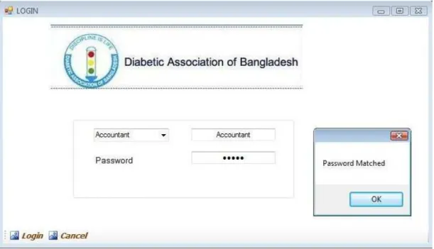
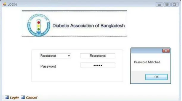
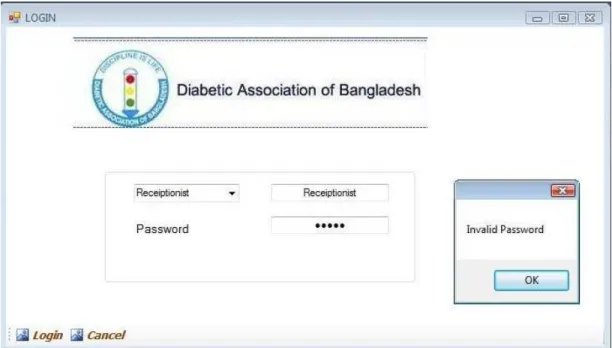
3.3 Security feature of FRONT END ………96
3.4 Implementation of Insert, Delete, Update buttons &
Search Option ………107
4. CONCLUSION & FUTURE WORK
………
115
4.1 Conclusion ………115
4.2 Future Work ………115
4.2.1 Gridline View Features ……… 116
4.2.2 Trigger Features ………129
REFERENCES
………
133
APPENDIX
………
135
P
P
R
R
E
E
F
F
A
A
C
C
E
E
Our thesis is about Designing and Interfacing a Hospital-Based Database System. It forms a basic entity of the management of a Hospital. Hence, it is
very important for the system to be reliable, user friendly, and should be properly functional for a long time without cropping up of any errors.
To start with the system study we visited Bangladesh Institute of Research and Rehabilitation for Diabetes, Endocrine and Metabolic Disorders (BIRDEM). We saw their system, studied it and tried to develop a better system. Our system is an automated system for Hospital Management. This gave us the idea of the different fields that ought to be in a Hospital Management System such as patient registration, his/her advance payment, the records, the details etc. and also how a software system can make the work easy both for the hospital staff and the patients. Moreover, the evaluation helped us to arrive at the conclusion that the automated software is far more superior to the manual ones.
ABSTRACT
Our motive is to develop a software that is very much user friendly and easy to gather information in a very short time. We try to make our software reliable and comfortable.
As our thesis paper is on Designing and Interfacing a Hospital Management System (A Case Study of BIRDEM) we divide our work into two basic parts Designing part and Interfacing Part.
® We give a flow chart on our work division in THESIS OVERVIEW part.
Chapter 1 Introduction
In this chapter we discuss the definition of Database and its usefulness. We also describe the reason to take HOSPITAL MANAGEMENT SYSTEM as our thesis work.
Chapter 2 Designing the Database System
In this chapter we describe the entities and attributes. We draw the Entity Relationship Diagram (ERD) and Tables. We determine the attributes of tables and its data types. We also find functional dependencies and normalize all the tables. Then we implement our database in SQL Server and finally we execute some complex queries on the system.
Chapter 3 Interfacing the Database System using .Net Framework.
We made a research on Interface Design Guidelines and designed our front end in C#. We applied some of the guidelines in our front end.
We control our software security using C#. We Insert Delete, Update and Search data from the database in our software. We used a DLL file so that we
can easily access to any Operating System and we don’t need to load our database.
Chapter 4 Conclusion and Future Work.
We tried to Save, Delete and Update data using Data Grid view and we also tried to use Trigger in SQL Server but we cannot complete them. So we include it as a part of future work.
C H A P T E R 1
INTRODUCTION
What is a Database?
A Database is a collection of records which are stored on a computer; a database organizes the data according to database models such as a relational model. [1]
Why do we need Databases?
Databases collect items on which the user can carry out various operations such as viewing, navigating, creating tables, and searching. Databases can be seen as a symbolic form of the computer age. [2]
We use databases for these reasons. Such as,
1. We use database because we can easily manipulate, edit or delete data. 2. Data are kept organized in a database so we can easily retrieve data. 3. Easy to find out desired data.
4. Data are secured.
Advantages of Database
Reduced Data Redundancy.
Reduced updating errors and increased consistency.
Greater data integrity and independence from applications programs.
Improved data access to users through use of host and query languages.
Improved data security.
Reduced data entry, storage, and retrieval costs.
Facilitated development of new application programs. [3]
In our thesis Designing and Interfacing a Hospital-Based Database System (A case study of BIRDEM) we can see two basic parts.
Designing &
Interfacing
Our Thesis Teacher Ms. Rosina Surovi Khan decided that we have to complete the design part in semester 4/1 and interfacing part in semester 4/2. In the introductory class of the thesis our respected madam suggested to select a specific database system to work on.
# Choosing Hospital Management System for our thesis
We study and select three systems at first. The systems were Banking System
Computer Sales Management System Hospital Management System
We saw the demos of the respective systems from different sources and all the group members decided to do the thesis on Hospital Management System (A Case Study of BIRDEM) because the system is less complex and easy to study. Most Banking Systems and Computer Sales Management Systems are controlled using online based software where users can access from any part of the
to choose Hospital Management System based on a Case Study of BIRDEM. We try our best to make the system efficient and user friendly with the help of our database and front end software.
# Thesis Overview
DATABASE
DESIGNING
INTERFACING
Determining Entities and Attributes
Entity Relationship Diagram Relational Model Normalization Implementation in SQL Server Complex Queries Research on Interface Design Guidelines Front End Design
Security feature of Front End
Implementation
(Insert, Delete, Update Buttons and Search Option)
C H A P T E R 2
DESIGNING THE DATABASE SYSTEM
2.1 Determining Entities and Attributes
Entity
An entity is something that has a distinct, separate existence, though it need not be a material existence. In particular, abstractions and legal fictions are usually regarded as entities. In general, there is also no presumption that an entity is animate. Entities are used in system developmental models that display communications and internal processing of, say, documents compared to order processing.
An entity could be viewed as a set containing subsets.
A DBMS entity is either a thing in the modeled world or a drawing element in an Entity Relationship Diagram(ERD) .[4]
Attribute
An attribute is a specification that defines a property of an object, element, or file. It may also refer to or set the specific value for a given instance of such.
Attributes should more correctly be considered metadata. It is frequently and generally a property of an entity.
An attribute of an object usually consists of a name and a value; of an element, a type or class name; of a file, a name and extension.[5]
Data Type
A data type (or datatype): In programming, a classification identifying one of various types of data, as floating-point, integer, or Boolean, stating the possible values for that type, the operations that can be done on that type, and the way the values of that type are stored.[6]
We think our best and determine the entities and attributes for our Database System. The Entities and Attributes are given below.
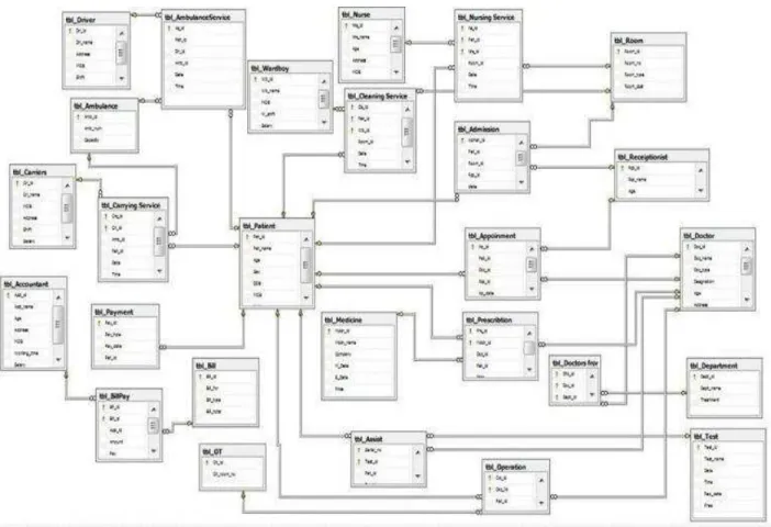
2.2 Entity Relationship Diagram (ERD):
We draw the Entity Relationship Diagram (ERD) very carefully and efficiently for the whole system of BIRDEM.
We were able to cover all probable information of BIRDEM in our ERD. The ERD is given below:
2.3 Relational Model:
After completing the ERD successfully we made the relational model (table schemas) taking into account all the entities and the relationships.
Patient Table:-
Room Table:-
Room_id Room_No Room_type Room_cost
Receptionist Table:-
Rcp_id Rcp_name Age Address MOB shifting salary
Admission Table:-
This is a junction table between Patient, Receptionist & Room tables.
Admsn_id Pat_id Room_id Rcp_id date time
Doctor Table:-
Doc_id Doc_name Doc_type Designation Age Address MOB Passed_from Salary
Appointment Table:-
This is a junction table between Patient, Receptionist & Doctor tables.
Ap_id Pat_id Doc_id Rcp_id apnmt_date apnmt_time
Bill Table:-
Bill_id Bill_for Bill_type Bill_ total
Accountant Table:-
Acct_id Acct_name Age Address MOB Working_time Acct_salary
Payment Table:-
This is a junction table between Patient, Bill & Accountant Tables.
Medicine Table:-
Mdcn_id Mdcn_name Company m_date e_date price
Prescription Table: -
This is a junction table between Patient, Doctor & Medicine tables.
Prs_id Doc_id Mdcn_id Pat_id date Fee
Test Table:-
Test_id Test_name date rep_date fee
Assist Table:-
This is a junction table between Patient, Doctor & Test tables.
Serial_no Pat_id Doc_id Test_id time date
OT Table:-
Ot_id Ot_room_no
Operation Table:-
This is a junction table between Patient, Doctor & OT tables.
Op_id Doc_id Pat_id Ot_id Op_date Op_time
Department Table:-
Dept_id Dept_name treatment
Doctor_from_Department Table:-
This is a junction table between Doctor & Department tables.
Dfd_id Doc_id Dept_id
Nurse Table:-
Nursing_Service Table:-
This is a junction table between Patient, Room & Nurse tables.
Ns_id Pat_id Nrs_id Room_id
Ward Boy Table:-
Wb_id wb_name MoB w_shift Salary
Cleaning Service Table:-
This is a junction table between Patient, Room & Ward Boy tables.
Cls_id Pat_id Wb_id Room_id
Driver Table:-
Dr_id Dr_name Mob Address Shift Salary
Ambulance Table:-
Amb_id Amb_num Capacity
Ambulance Service Table:-
This is a junction table between Patient, Driver & Ambulance tables.
As_id Pat_id Dr_id Amb_id
Carriers Table:-
Carrying Service Table:-
This is a junction table between Patient, Ambulance & Carriers tables.
CS_id Cr_id Amb_id Pat_id
2.3.1 Relational Tables’ Descriptions
Patient tableAttributes Data type Comments
Pat_id int Unique id for a Patient Pat_name varchar(20) Patient’s Name
Age int Patient’s Age
Sex varchar(20) Patient is Male or Female
Address varchar(20) Patient’s Address Dob varchar(20) Date of Birth
Mob int Mobile Number
Room table
Attributes Data type Comments
Room_id int Unique id for a Room Room_no varchar(20) Room number
Receptionist table
Attributes Data type Comments
Rcp_id int Unique id for a Receptionist
Rcp_name varchar(20) Receptionist’s name
Age int Receptionist’s age
Address varchar(20) Receptionist’s Address
MOB int Mobile Number
Shifting varchar(20) Receptionist working shift Salary int Salary a Receptionist gets
Admission table
Attributes Data type Comments
Admsn_id int Unique id for an Admission
Pat_id int Unique id for a Patient Room_id int Unique id for a Room
Rcp_id int Unique id for a
Receptionist Date varchar(20) Date of Admission
Doctor table:
Attributes Data type Comments
Doc_id int Unique id for a Doctor Doc_name varchar(20) Doctor’s name
Doc_type varchar(20) Doctor’s specialty
Age int Doctor’s age
Address varchar(20) Doctor’s address
Mob int Mobile Number
Designation varchar(20) Doctor’s designation
Passed_from varchar(20) Doctor is passed from which medical college
Salary int Salary of a doctor
Appointment table
Attributes Data type Comments
Apnmt_id int Unique id for an Appointment Pat_id int Unique id for a Patient
Doc_id int Unique id for a Doctor Rcp_id int Unique id for a Receptionist Apnmt_date varchar(20) Date of an Appointment
Bill table
Attributes Data type Comments
Bill_id int Unique id for a Bill Bill_for varchar(20) Purpose of the bill Bill_type varchar(20) Bill either in Cash or
Check
Bill_total int Total amount
Accountant table
Attributes Data type Comments
Acct_id int Unique id for an Accountant
Acct_name varchar(20) Accountant’s Name
Age int Accountant’s age
Address varchar(20) Accountant’s Address
Mob int Mobile Number
Acct_salary int Salary of an Accountant
Payment table
Attributes Data type Comments
Pay_id int Unique id for a Payment Bill_id int Unique id for a Bill Pat_id int Unique id for a Patient Acct_id int Unique id for an Accountant Pay_type varchar(20) Payment in Cash or Check Pay_date varchar(20) Date of Payment
Medicine table
Attributes Data type Comments
Mdcn_id int Unique id for a Medicine Mdcn_name varchar(20) Medicine’s Name
company varchar(20) Medicine’s Company M_date varchar(20) Manufacture Date
E_date varchar(20) Expire Date
Prescription table
Attributes Data type Comments
Prs_id int Unique id for a Prescription
Doc_id int Unique id for a Doctor Mdcn_id int Unique id for a Medicine
Pat_id int Unique id for a Patient Date varchar(20) Date of the Prescription Time varchar(20) Time of the Prescription
Fee varchar(20) Prescription Fees
Test table
Attributes Data type Comments
Test_id int Unique id for a Test Test_name varchar(20) Name of the Test
Date varchar(20) Date of Test Rep_date varchar(20) Date of the Report
Assist table
OT table
Attributes Data type Comments
Ot_id int Unique id for an
Operation Theater (OT) Ot_room_no varchar(20) OT Room Number
Attributes Data type Comments
Serial_no int Unique id for an Assisted Test directed to a Patient by a Doctor
Pat_id int Unique id for a Patient Doc_id int Unique id for a Doctor Test_id int Unique id for a Test
Date varchar(20) Date of the Assisted Test Time varchar(20) Time of the Assisted Test
Operation table
Attributes Data type Comments
Op_id int Unique id for an Operation
Doc_id int Unique id for a Doctor Pat_id int Unique id for a Patient
Ot_id int Unique id for an OT Op_date varchar(20) Date of the Operation Op_time varchar(20) Time of the Operation
Department table
Attributes Data type Comments
Dept_id int Unique id for a Department
Dept_name varchar(20) Department’s name treatement varchar(20) Treatments of a patient
Doctor_from_Department table
Attributes Data type Comments
Dfd_id int Unique id for a
DoctorsfromDepartment junction table
Doc_id int Unique id for a Doctor Dept_id int Unique id for a Department
Nurse table
Attributes Data type Comments
Nrs_id int Unique id for a Nurse Nrs_name varchar(20) Nurse’s Name
Age int Nurse’s age
Address varchar(20) Nurse’s Address
Mob int Mobile Number
Nrs_wo_shift varchar(20) Nurse working Shift example
morning,day,evening,night Experience varchar(20) Nurse’s Experience
Nursing_Service table
Attributes Data type Comments
Ns_id int Unique id for a Nursing Service
Pat_id int Unique id for a Patient Nrs_id int Unique id for a Nurse Room_id int Unique id for a Room
Date varchar(20) Date of Nursing Service Time varchar(20) Time of Nursing Service
Ward_boy table
Attributes Data type Comments
Wb_id int Unique id for a Ward Boy Wb_name varchar(20) Ward Boy’s Name
Mob int Mobile Number
W_shift varchar(20) Working shift of a Ward Boy salary int Salary of a Ward boy
Cleaning_Service table
Attributes Data type Comments
Cls_id int Unique id for a Cleaning Service
Pat_id int Unique id for a Patient Wb_id int Unique id for a Ward Boy Room_id int Unique id for a Room
Date varchar(20) Date of Cleaning Service Time varchar(20) Time of Cleaning Service
Driver table
Attributes Data type Comments
Dr_id int Unique id for a Driver Dr_name varchar(20) Driver’s Name
mob int Mobile Number
address varchar(20) Driver’s Address
Shift varchar(20) Working shift of a Driver salary int Salary of a Driver
Ambulance table
Attributes Data type Comments
Amb_id int Unique id for an
Ambulance
Amb_num varchar(20) Ambulance’s Number Capacity int Capacity of an Ambulance
Ambulance_Service table
Attributes Data type Comments
As_id int Unique id for an Ambulance Service
Pat_id int Unique id for a Patient Dr_id int Unique id for a Driver Amb_id int Unique id for an Ambulance Date varchar(20) Date of the Ambulance Service Time varchar(20) Time of the Ambulance Service
Carriers table
Attributes Data type Comments
Cr_id int Unique id for a Carrier who will carry patients inside the hospital’s premises from the ambulance.
Cr_name varchar(20) Carrier’s Name
Mob int Mobile Number
Address varchar(20) Carrier’s Address Salary int Salary of a Carrier
Carrying_Service table
Attributes Data type Comments
Cs_id int Unique id for a Carrying Service
Cr_id int Unique id for a Carrier Amb_id int Unique id for an Ambulance
Pat_id int Unique id for a Patient Date varchar(20) Date of the Carrying Service Time varchar(20) Time of the Carrying Service
2.3.2 Explanation of Relational Model
# Relationship between Receptionist, Patient and Room Entities in the ER Model:
1 Receptionist can admit 1 Patient in 1 Room in a certain date and time. 1 Receptionist can admit in 1 Room 1 Patient in a certain date and time. In 1 Room, 1 Patient is admitted by 1 Receptionist in a certain date and
time.
So the relationship is a Ternary Relationship named Admission (in the diamond) with cardinality ratio from Patient to Receptionist to Room as 1 to 1 to 1.
# Relational model for Receptionist, Patient and Room Entities:
Receptionist, Patient and Room Entities become Receptionist, Patient and Room tables.
Patient Table:-
Pat_id Pat_name Age Sex DOB MOB Address
Room Table:-
Room_id Room_No Room_type Room_cost
Receptionist Table:-
Rcp_id Rcp_name Age Address MOB shifting salary
The junction Admission also becomes a table. Admission Table:-
admsn_id Pat_id Room_id Rcp_id Date time
Primary Key of the Patient Table goes to Admission Table as Foreign Key. Primary Key of the Room Table goes to Admission Table as Foreign Key. Primary Key of the Receptionist Table goes to Admission Table as Foreign
Key.
admsn_id is a Primary key in the Admission Table. Pat_id from Patient Table, Room_id from Room Table and Rcp_id from Receptionist Table become Foreign Keys in the Admission Table.
In a similar way, as cardinality ratio for Receptionist_Patient_Doctor relationship is 1 to 1 to 1, Receptionist, Patient and Doctor entities become separate tables along with a junction Appointment table which has Rcp_id, Pat_id and Doc_id as foreign keys. Similar logic applies to Patient_Ambulance_Driver relationship with cardinality ratio 1 to 1 to 1.
# Relationship between Doctor and Department Entities in the ER Model:
1 Doctor can be from 1 or Many Departments. 1 Department may have 1 or Many Doctors.
So it is a Many to Many relationship named Doctor from Department (in the diamond).
# Relational model for Doctor and Department Entities:
Doctor and Department Entities become Doctor and Department tables. Doctor Table:-
Doc_id Doc_name Doc_type Designation Age Address MOB Passed_from Salary
Department Table:-
Dept_id Dept_name treatment
The junction table Doctor from Department also becomes a table. Doctor_from _Department Table:-
Dfd_id Doc_id Dept_id
Primary Key of the Doctor Table goes to Doctor_from_Department Table as part of Primary Key.
Primary Key of the Department Table goes to Doctor_from_Department Table as part of Primary Key.
Since the Cardinality Ratio from Doctor to Department is Many to Many, Dfd_id is a part of Primary key in the Doctor_from_Department Table. Doc_id from Doctor Table and Dept_id from Department Table become parts of Primary Key in the Doctor_from_Department Table.
# Relationship between Patient, Doctor and Medicine Entities in the ER Model:
1 Doctor gives 1 patient 1 or more medicine. 1 patient takes 1 medicine prescribed by 1 doctor. 1 medicine is prescribed by 1 doctor to 1 patient.
So the relationship is a Ternary Relationship named Prescription (in the diamond) with a Cardinality Ratio from Patient to Doctor to Medicine 1 to 1 to Many.
# Relational model for Patient, Doctor and Medicine Entities:
Patient, Doctor and Medicine Entities become Patient, Doctor and Medicine tables.
Patient Table:-
Pat_Id Pat_name Age Sex DOB MOB Address
Doctor Table:-
Doc_id Doc_name Doc_type Designation Age Address MOB Passed_from Salary
Medicine Table:-
Mdcn_id Mdcn_name company m_date e_date price
Prescription Table: -
This is a junction table between Patients, Doctor & Medicine Table.
Prs_id Doc_id Mdcn_id Pat_id date fee
Primary Key of the Patient Table goes to Prescription Table as Foreign Key.
Primary Key of the Doctor Table goes to Prescription Table as Foreign Key.
Primary Key of the Medicine Table goes to Prescription Table as part of Primary Key.
Since the Cardinality Ratio from Patient to Doctor to Medicine 1 to 1 to M, Prs_id is a Primary key in the Prescription Table. Pat_id from Patient Table,
Doc_id from Doctor Table and Mdcn_id from Medicine Table become Foreign Keys in the Admission Table.
In a similar way relational tables have been designed for Patient-Doctor-Test, Patient-OT-Doctor, Patient-Bill-Accountant relationships with cardinality ratio 1 to 1 to M. Similar logic applies for Patient-Ambulance-Carrier relationship with cardinality ratio 1 to 1 to M.
#Relationship Between Patient,Room & Nurse Entities in the ER Model
1 room is fixed for 1 Patient to provide nursing service for 1 or Many nurses in a certain date.
1 patient receives nursing service from 1 Nurse in 1 Room in a certain date.
1 nurse can render proper services in 1 room to many patients in a certain date.
So it is a Ternary Relationship named Nursing Services (in the diamond)
#Relational model between Patient, Nurse and Room Entities:- Patient Table:-
Pat_id Pat_name Age Sex DOB MOB Address
Room Table:-
Nurse Table:-
Nrs_id Nrs_name Age Address Mob Nrs_wo_shift experience Salary
Nursing Service Table:-
This is a junction table between Patient, Room and Nurse Table.
Ns_id Pat_id Nrs_id Room_id
Primary Key of the Patient Table goes to Nursing Service Table as part of Primary Key.
Primary Key of the Nurse Table goes to Nursing Service Table as part of Primary Key.
Primary Key of the Room Table goes to Nursing Service Table as Foreign Key.
Since the Cardinality Ratio from Room to Patient to Nurse is 1to M to M. Ns_id
from Nurse Table become parts of Primary Key in the Nursing Service Table. Room_id from Room Table becomes Foreign Key in the Nursing Service Table. In a similar way relational tables are created for Patient-Room-Wardboy relationship with cardinality ratio 1 to M to M.
2.4 Relational Database Design
Relational databases are the most commonly used database today. It uses
the table to structure information so that it can be readily and easily
searched through.
To make a Relational database design we have to be clear about two parts:
1.
Functional Dependency
2.
Normalization
2.4.1 Functional Dependencies
Definition of functional dependencies:
Given a relational schema R (A1, A2, ..., An) and X, Y {A1, ..., An}. Then X -> Y means that for every extension of R, the following holds:
R contains no two tuples that are equal in all values of X but differ in at least one value of Y.
(Pronunciation: "X determines Y functionally" "Y is functionally dependent of X").
Example:
Student (matNr, name): {matNr} -> {name}
Definition of
full
functional dependencies:
Prerequisites as in Definition 1.Y is said to be fully functionally dependent of X, if there is no proper subset X’ ⊂ X, Where X’ -> Y. Notation: X => Y.
Example:
A University Database:-Class (classId, room, day, pName) {classId, room} -> {pName}
{classId, day, pName} -> {room} {classId} => {pName}
{classId} => {room} [7]
2.4.2 Normalization
Normalization is the process of organizing data in a database. This includes creating tables and establishing relationships between those tables according to rules designed both to protect the data and to make the database more flexible by eliminating redundancy and inconsistent dependency.
It has mainly two goals:-
First goal: eliminate redundant data
For example, storing the same data in more than one table Second Goal: ensure data dependencies make sense
For example, only storing related data in a table
Benefits of Normalization:
Less storage space Quicker updates
Easier to add data Flexible Structure
Bad database designs results in:
Redundancy: inefficient storage.
Anomalies: data inconsistency, difficulties in maintenance.[7]
1NF, 2NF, 3NF, BCNF are some of the early forms in the list that address this problem.
First Normal Form (1NF)
Definition:
A relation is in first normal form if it contains only simple, atomic values for attributes, no sets. Example:
Name Offspring Child Age Place Muller Christa 12 Peter 10 Iris 9 Stuttgart Schmidt Martin 17 Rainer 18 Trier
The value of an attribute can be a relation by itself. => Operations in the model are much more complicated => In order to keep the model simple: 1NF
Ways to normalize the above relation: First attempt:
Person (name, place, child1, child2, child3)
=> Not good. Reason: either not enough available columns for some data records (How many children can a person have??) Or, if there are enough columns to provide for all thinkable cases, waste of much space (many NULL values).
Second attempt: Person:- pName place Muller Stuggart Schmidt Trir Child:-
pName chName age Muller Christa 12 Muller Peter 10
Muller Iris 9
Schmidt Martin 17 Schmidt Rainer 18
Advantage:
This requires just the right amount of space that is actually needed.
Disadvantage:
It requires an additional table. pName is redundantly stored.
Second Normal Form (2NF)
Definitions:
Definition of second normal form (simple version):
A relation is in 2NF, if it is in 1NF and every non-primary-key attribute is fully functionally dependent on the primary key of the relation.
Definition of second normal form (extended version):
A relation is in 2NF, if it is in 1NF and every non-candidate-key attribute is fully functionally dependent on every candidate key.
Example:- A University Database:
TA (matNr, classId, sName, hours, taSalary)
Full functional dependencies:
{matNr, classId} => {hours} {matNr, classId} => {taSalary} {matNr} => {sName}
TA (matNr, classId, sName, hours, taSalary) Student (matNr, sName)
Redundancy since the name is repeated for every occurrence of the same Matrikel Number.
Solution:
Move the dependency {matNr} => {name} to a separate relation. => Relation "Student"
Third Normal Form (3NF)
Definition:-
A functional dependency X->Y in a relation R is called a transitive dependency, if R contains a set of attributes, Z for which holds:
. A chain Exists. .X->Z->Y
. Y is not a part of primary key . Z is not a super key and . X->Z-> Y
Y is then called transitively dependent on X via Z. Definition of Third Normal Form:
A Relation is in 3NF, if it is in 2NF and no non primary key attributes is transitively dependent on the primary key.
Example:-
Functional dependencies:
{matNr, classId} => {hours} {matNr, classId} => {taSalary}
Assumption:
{hours} => {taSalary}
There is the following transitive dependency: {matNr, classId} => {hours} => {taSalary}
Since taSalary is not an attribute in a candidate key and hours is not a superkey, TA is not in 3NF.
There is unnecessary redundancy since taSalary is repeated for each occurrence of the same value of hours.
Solution:
Move the dependency {hours} => {taSalary} to a separate relation. Example:
TANew (matNr, classId, hours) and TASalary (hours, taSalary).
Boyce Coded Normal Form (BCNF)
A relation R is in 3NF relation and for a dependency X->A from an attributes set X to an attributes A holds that,
X is not a super key
In addition, A is a part of a primary key Then this relation is not also in BCNF. In all other cases, 3NF and BCNF are identical.
BCNF is a little stronger than 3NF. In most cases, relations in 3NF are also in BCNF.
The alternative definition of BCNF shows in comparison to the 3NF definition how the two differ: in BCNF, X must always be a super key; in 3NF it does not need to be a super key if A is part of a candidate key.
A relation is in BCNF, if and only if, every determinant is a candidate key.
No part of the primary key is Fully Functional Dependent on the non primary key.
Example:-
Relation Speedlimits (town, streetSegment, postcode, speed)
Full functional dependencies:
• {town, streetSegment} => {postCode} • {town, streetSegment} => {speed} • {postCode} => {town}• {postcode, streetSegment} => {speed}
Candidate keys:
• (town, streetSegment) • (postCode, streetSegment)
Speedlimits is in 3NF:
• 1NF by definition
2NF since all non-primary-key attributes are fully functionally dependent on the primary Key. For the extended definition: speed is the only attribute that is not part of a Candidate key, and it is fully functionally dependent not only on the primary key, but also on the other candidate.
• 3NF since the only non-candidate-key attribute is speed, and the only transitive Dependencies ending in speed would be from one of the keys to the other and then to speed. However, transitive dependencies where the middle set is a candidate key do not violate the definition of 3NF.
But BCNF is violated:
The problematic dependency is from an attribute (postcode) which is not a superkey to a part (town) of the primary key.
town streetSegment postcode speed Stuttgart A-Str 70000 30 Stuttgart B-Str 70000 30 Stuttgart C-Str 70000 50
Redundancy: postCode implies the town => unnecessary repetition
Transforming to BCNF:
1. Attempt:
Speedlimit (town, streetSegment, speed) Codes (postCode, town)
Schema is now in BCNF.
• The dependency {town, streetSegment} => {postCode} is no longer recognizable.
2. Attempt:
Speedlimit (town, streetSegment, speed) PostCodes (streetsegement, postCode)
BCNF But:
• The dependency {town, streetSegment} => {postCode} is again not recognizable. • The decomposition is lossy again!
3. Attempt:
Speedlimit (postCode, streetSegment, speed) Codes (postCode, town)
Now both relations are in BCNF, and the decomposition is lossless.
However, the dependencies {town, streetSegment} => {postCode} and {town, street-
Segment} => {speed} are lost. It is possible to show:
• A relation that is not in BCNF can always be losslessly decomposed towards BCNF.
• A lossless decomposition into BCNF that preserves all dependencies does not always exist. [7]
FULFILMENT OF NORMAL FORMS:
Room Table:-Room_id Room_no Room_type Room_cost
{Room_id} => {Room_no} Functional Dependency Exist 2 different room no’s do not correspond to the same Room_id.
{Room_id} => {Room _type} Functional Dependency Exist 2 different room types’ do not correspond to the same Room_id
{Room_id} => {Room cost} Functional Dependency Exist 2 different room cost’s do not correspond to the same Room_id
Relation :( Room_id, Room_No, Room_type, Room_cost) Full Functional Dependencies:
{Room_id} => {Room_no} {Room_id} => {Room_type} {Room_id} => {Room_cost}
1NF:-
Attributes do not have sub attributes. So the relation is in 1NF.
So the relation is in 2NF. 3NF:-
No chain Exists.
So the relation is in 3NF.
BCNF:-
No part of the primary key is Fully Functional Dependent on the non primary keys. So the relation is in BCNF.
Bill Table:-
Bill_id Bill_for Bill_type Bill_ total
{Bill_id} => {Bill_for} Functional Dependency Exist. 2 different Bill_for’s do not correspond to the same Bill_id.
{Bill _id} => {Bill_type} Functional Dependency Exist. 2 different Bill_type do not correspond to the same Bill_id.
{Bill _id} => {Bill total Functional Dependency Exist. 2 different Bill total do not correspond to the same Bill_id.
Relation :( Bill_id, Bill_for, Bill total, Bill_type) Full Functional Dependency:
{Bill_id} => {Bill_for}
{Bill_id} => {Bill_type}
1NF:-
Attributes do not have sub attributes. So the relation is in 1NF.
2NF:-
Every non primary key is Fully Functional Dependent on the primary key. So the relation is in 2NF
3NF:-
No chain Exists.
So the relation is in 3NF. BCNF:-
No part of the primary key is Fully Functional Dependent on the non primary key. So the relation is in BCNF.
In a similar way Bill, Doctor, Accountant, Receptionist, Driver, Ambulance, Carriers, OT, Medicine, Test, Department and Nurse Tables fulfill all the normal forms.
JUNCTION TABLES:
Admission Room Table:-This is a junction table between Patient, Room, and Receptionist Table Admsn_id Room_id Pat_id Rcp_id Date Time
Full Functional Dependencies:
{admsn_id} => {Room_id} Functional Dependency Exist {admsn_id} => {Rcp_id} Functional Dependency Exist {adsn_id} => {Date} Functional Dependency Exist
{admsn_id} => {Time} Functional Dependency Exist {admsn_id} => {Pat_id} Functional Dependency Exist 1NF:-
Attributes do not have sub attributes. So the relation is in 1NF.
2NF:-
Every non primary key is Fully Functional Dependent on the primary key. So the relation is in 2NF.
3NF:-
No chain Exists.
So the relation is in 3NF. BCNF:-
No part of the primary key is Fully Functional Dependent on the non primary keys. So the relation is in BCNF.
In a similar way Ambulance Service and Appointment Tables fulfill all the normal forms.
Prescription Table:-
This is a junction table between Patient, Medicine & Doctor Table. Prs_id Doc_id Mdcn_id Pat_id Date Fees Time
Full Functional Dependencies:
{Prs_id, Mdcn_id}=> {Doc_id} Functional Dependency Exist {Prs_id, Mdcn_id}=> {Pat_id} Functional Dependency Exist {Prs_id, Mdcn_id}=> {Date, Fees, Time} Functional Dependency Exist
Relation: (Prs_id, Mdcn_id, Doc_id, Pat_id, Date, Fees, Time) {Prs_id, Mdcn_id}=> {Doc_id}
{Prs_id, Mdcn_id}=> {Pat_id} {Prs_id, Mdcn_id}=> {Date} {Prs_id, Mdcn_id}=> {Time} {Prs_id, Mdcn_id}=> {Fees} 1NF:-
Attributes do not have sub attributes. So the relation is in 1NF.
2NF:-
Every non primary key is Fully Functional Dependent on the primary key. So the relation is in 2NF.
3NF:-
No chain Exists.
So the relation is in 3NF. BCNF:-
No part of the primary key is Fully Functional Dependent on the non primary keys. So the relation is in BCNF.
In a similar way Assist, Carrying Service, Cleaning Service, Operation and Nursing Service tables fulfill all normal forms.
VIOLATION OF NORMAL FORM:
Payment Table:-
This is a junction table between Patients, Bill & Accountant tables. Pay_id Pat_id Bill_id Acct_id Pay_type Pay_date
For Payment relation, the following functional dependencies exist: {Pay_id}=> {Pay_Type, Pay_date, Pat_id}
Two different patient ids, payment dates and payment types cannot correspond to the same payment id. So Pay_Type, Pay-date and Pat_id are fully functionally dependent on Pay_id.
{Bill_id}=> {Acct_id, Pat_id}
Similarly two different accountant ids and patient ids cannot correspond to the same bill id. So Acct_Id and Pat_id are fully functionally dependent on Bill_id. Based on the above functional dependencies:
The relation is in 1NF.
The relation is not in 2NF because all non-primary keys are not fully functionally dependent on the primary key (Pay_id, Bill_id). So we split the relation to make it 2NF.
Payment2 (Bill_id, Acct_id, Pat_id) The relations are now in 2NF.
3NF:
There is no chain.
So the relations are in 3NF.
BCNF:
No Part of the primary key (Pay_Id, Bill_Id) is fully functionally dependent on any non primary key. So the relations are in BCNF.
2.5
Implementation in SQL Server:
After Normalization, we implemented our Database in SQL Server.
There were 27 tables and each of them was connected accurately in
the SQL Server’s Entity Relationship Diagram. Then we entered the
data in the corresponding database tables.
2.5.1 Creation of Tables and Insertion of Data:
In our thesis we create tables and insert data using SQL server and
SQL Language.
MAIN TABLE
Insert Values into Patient Table
In this way we create all the main tables and insert data in them.
Junction Table
Insert Values into Admission Table
In this way we create all the junction tables and insert data in them.
2.5.2 Sample Data values of Tables
Patient tableReceptionist table
Admission room table
Doctor table
Appointment table
Accountant table
BillPay table
Payment Table
Prescription table
Test table
Assist table
Operation table
Department table
Doctor_form_department table
Nursing service table
Ward_boy table
Cleaning service table
Ambulance table
Ambulance service table
Carriers table
2.6 Complex Queries
After completing the implementation we retrieved different
information from the system by joining 2 or more tables of the
system. Sample Examples are given below:
Question 1
Which tests are suggested by doctor Selima to which Patients?
Query 1:
select Pat_name, Doc_name, Test_name from tbl_Patient, tbl_Doctor, tbl_Test , tbl_Assist where Doc_name='Selima' and tbl_Doctor.Doc_id = tbl_Assist.Doc_id and Tbl_Patient.Pat_id = Tbl_Assist.Pat_id and tbl_Test.Test_id = tbl_Assist.Test_id Output:
Question 2
Which doctors prescribed which medicine to patient Mamun?
Query 2:
select Pat_name, Doc_name, Mdcn_name from tbl_Patient, tbl_Doctor, tbl_Medicine, tbl_Prescription where Pat_name = 'Mamun' and tbl_Patient.Pat_id = tbl_Prescription.Pat_id and tbl_Doctor.Doc_id = tbl_Prescription.Doc_id and tbl_Medicine.Mdcn_id =
Output 2:
Question 3:
Which Doctors are from which Department and they passed from which college and got salaries below 20000 taka?
Query 3
select Doc_name,Passed_from,Dept_name from tbl_Doctor, tbl_Department, tbl_DFD where Salary <20000 and tbl_Doctor.Doc_id =
tbl_DFD.Doc_id and tbl_Department.Dept_id = tbl_DFD. Dept_id
Output 3:
Question-4
Which doctor conducted the Urine Test for which Patient at 11.00 AM?
Query -4
select pat_name,doc_name from tbl_Patient,tbl_Doctor,tbl_Test,tbl_Assist where
tbl_Assist.Time='11.00AM' and tbl_Test.Test_name='Urine' and
Output 4:-
Question 5:
Which Patient is carried by which driver in Ambulance serial no 5?
Query -5:
select Pat_name,Dri_name from tbl_Patient,tbl_Driver,tbl_AmbulanceService where Amb_id = 5 and tbl_Patient.Pat_id=tbl_AmbulanceService.Pat_id and tbl_Driver.Dri_id =
tbl_AmbulanceService.Dri_id
Output 5 :-
Question 6:
In which time receptionist Rasel appointed patient Kamal to Doctor Selima?
Query 6:
Select pat_name,Ap_time from tbl_patient,tbl_Receiptionist,tbl_Appoinment,tbl_Doctor where
Rcp_name='Rasel'and Doc_name='Selima'and pat_name='kamal' and
tbl_patient.pat_id=tbl_Appoinment.pat_id and tbl_Receiptionist.Rcp_id=tbl_Appoinment.Rcp_id

![Fig: the DLL file used in our Software Source: [22]](https://thumb-us.123doks.com/thumbv2/123dok_us/10613791.2948693/125.918.85.848.80.608/fig-dll-file-used-software-source.webp)

