AUTOMATED VALIDATION FOR SYNCHRONOUS
REACTIVE EMBEDDED SYSTEMS
Honors Research Thesis
Presented in Partial Fulfillment of the Requirements for
the Degree Bachelor of Science with Honors Research Distinction
at The Ohio State University
By
Vahid Rajabian Schwart
* * * * *
Department of Electrical and Computer Engineering
The Ohio State University
2012
Thesis Committee:
Paolo Sivilotti, Co-Adviser
Ashok Krishnamurthy, Co-Adviser
Approved by
Co-Adviser
c
Copyright by Vahid Rajabian Schwart
ABSTRACT
Proper functionality is a necessity for systems used in safety-critical applications; consequently, software in these systems is often subject to rigorous validation and for-mal verification that aims at ensuring expected behavior. To aid in the design of these systems, several synchronous programming languages exist for describing determin-istic system models suitable for formal verification and validation. Examples of such synchronous languages include SIGNAL, Lustre, MRICDF, and Esterel. Common application domains for synchronous programs include avionics, automotive control, process control, and defense systems. In many cases, rigorous formal verification of these systems is unfeasible because the methods, such as theorem proving and model checking, are too expensive. A theorem proving approach requires a great deal of user involvement and expertise, and a model checking approach may not be feasible on systems of substantial complexity due to computation constraints. This thesis presents the design, implementation, and evaluation of SAGA, a prototype tool for the automated validation of synchronous reactive embedded systems. SAGA shifts the testing effort associated with critical systems from creating individual test cases manually to reasoning about the safety and environment properties of a system. The approach SAGA takes is to generate relevant inputs to the system-under-test from a user-specified environment description, and to validate the resulting system behavior against user-specified safety properties. This overview of SAGA includes a thorough
user’s guide and important implementation details. Additionally, the validation pro-cess with SAGA is qualitatively assessed. The assessment is done through a case study involving the celebrated steam boiler control specification problem. Results from this case study reveal the utility of SAGA in exposing non-trivial system errors.
ACKNOWLEDGMENTS
I would like to start by thanking my advisors, Paul Sivilotti and Ashok Krishna-murthy; Ashok for readily providing the means to making this thesis possible, and Paul for his diligent effort in working with me. Paul’s constant feedback throughout this demanding process and dedicated commitment to my thesis have been invaluable. From day one, he has trusted in my ability to meet the challenges at hand and has provided me with the needed guidance to do so.
The work presented in this thesis has come to fruition from my internship ex-perience at the Air Force Research Laboratory (AFRL). I would therefore like to thank William McKeever and Steven Drager, who served as my mentors at AFRL and provided me with the initial direction of my project. Without their support and guidance, this thesis would not have been possible. I would also like to thank my co-workers at AFRL, Matthew Anderson and Thomas Levy, for their assistance in this project and for the many technical discussions which have played a key part in my work.
Finally, I would like to thank the participants in my research group seminar at The Ohio State University (OSU): Ted Pavlic, Diego Zaccai, Derek Bronish, Yan Xu, Sanket Tavarageri, Aditi Tagore, and Jason Kirschenbaum. They have provided me with valuable commentary on my thesis and have made my undergraduate research experience at OSU an engaging and gratifying endeavor.
TABLE OF CONTENTS
Page Abstract . . . iii Dedication . . . v Acknowledgments . . . vi List of Tables . . . x List of Figures . . . xi Listings . . . xii Chapters: 1. Introduction . . . 11.1 Problem Statement and Motivation . . . 1
1.2 Contribution . . . 2
1.3 Related Work . . . 3
1.4 Thesis Organization . . . 5
2. Background and Theory . . . 6
2.1 Synchronous Programming Languages . . . 6
2.1.1 Synchronous Hypothesis . . . 7
2.1.2 Synchronous Validation . . . 7
2.2 SIGNAL . . . 8
2.2.1 Primitive Language Constructs . . . 9
3. An Overview of SAGA . . . 14 3.1 SAGA Defined . . . 14 3.2 Approach . . . 14 3.3 Environment Simulation . . . 16 3.4 Safety Validation . . . 19 4. Using SAGA . . . 22
4.1 Compiling and Running SAGA . . . 22
4.2 Specifying Initialization . . . 24
4.2.1 File Format . . . 24
4.2.2 Example: Cruise Control Initialization . . . 26
4.3 Specifying the Environment . . . 27
4.3.1 Syntax . . . 27
4.3.2 Example: Cruise Control Environment . . . 30
4.4 Specifying Safety Validation . . . 31
4.4.1 Syntax . . . 31
4.4.2 Example: Cruise Control Safety . . . 32
4.5 Interpreting Results . . . 33
5. Case Study: Steam Boiler . . . 36
5.1 Introduction . . . 36
5.2 Steam Boiler Specification . . . 37
5.2.1 Overview . . . 37
5.2.2 Implementation Limitations . . . 40
5.3 Validation . . . 40
5.3.1 From Specification to Safety Description . . . 41
5.3.2 Environment Simulation . . . 42
5.3.3 Nontrivial Bugs . . . 48
6. Design and Implementation Details . . . 50
6.1 Why SIGNAL? . . . 50
6.2 Testing Harness . . . 51
6.3 Evaluating Probabilities . . . 52
6.4 Handling Properties . . . 52
7. Conclusion . . . 55
7.1.1 Lessons from the Case Study . . . 56
7.2 Future Work . . . 56
Appendices: A. Cruise Control Program Listing . . . 58
B. Steam Boiler Files . . . 60
B.1 Initialization . . . 60
B.2 Safety Description . . . 62
B.3 Environment Description . . . 63
B.4 Program Listing . . . 65
LIST OF TABLES
Table Page
2.1 Assignment Statements in SIGNAL . . . 9
4.1 SAGA Operators . . . 29
5.1 Implementation Values of Physical Constants . . . 38
LIST OF FIGURES
Figure Page
1.1 Exponential Growth of Automaton State Space . . . 2
2.1 Synchronous Software Operation . . . 7
2.2 Cruise Control System Diagram . . . 10
3.1 Architecture Diagram of SAGA . . . 15
3.2 Safety Properties and the System State Space . . . 20
4.1 Cruise Control Simulation Log . . . 33
4.2 Speed Signal in Cruise Control . . . 34
4.3 A Safety Violation . . . 34
5.1 Steam Boiler Physical Diagram . . . 38
5.2 Steam Boiler Program Simplified Interface . . . 39
5.3 Steam Boiler Typical Operation: Water Level . . . 46
5.4 Steam Boiler Typical Operation: Steam Output . . . 46
5.5 Steam Boiler Stress Operation: Water Leak . . . 48
6.1 Testing Harness for Dynamic Synchronous Control . . . 51
LISTINGS
2.1 Cruise Control: Input and Output Interface . . . 11
2.2 Cruise Control: Internal Variables . . . 12
2.3 Cruise Control: Signal Assignments . . . 12
4.1 SAGA Help Menu . . . 22
4.2 Contents of “cruiseControl init.txt” . . . 26
4.3 Excerpt from “cruiseControl env.txt” . . . 30
4.4 Excerpt from “cruiseControl safe.txt” . . . 32
4.5 Cruise Control: A Bug Exposed . . . 34
4.6 Cruise Control: Altered Code . . . 35
5.1 Steam Boiler Safety Properties . . . 42
5.2 Following Program Orders . . . 43
5.3 Water Level . . . 44
5.4 Steam Production . . . 44
5.5 Unsolicited and Solicited Messages . . . 45
5.6 Simulating a water leak . . . 47
CHAPTER 1
INTRODUCTION
1.1
Problem Statement and Motivation
Proper functionality is a must for systems used in safety-critical applications; consequently, software in these systems is subject to rigorous validation and formal verification that aims at ensuring expected behavior [21, 1, 16]. The rise in autonomy in modern-day embedded systems has been accompanied by a rise in software com-plexity, which has made the verification and validation of these systems an increasing challenge [24, 19]. The failure of such systems, particularly in safety-critical appli-cations, can result in serious injury, loss of life, environmental damage, or negative economic repercussions [15, 9]. According to the National Institute of Standards and Technology, in 2002 the cost to the US economy due to software errors was estimated to be $59.5 billion [27].
The problems associated with current-day verification and validation (V&V) meth-ods also concern national security. In Technical Horizons, a report establishing the vision for U.S. Air Force key science and technology focus areas for 2010-2030, V&V is highlighted as a main research focus area [24]. The relative ease with which modern autonomous systems can be developed poses an advantage to adversaries who may choose to field such systems without the burden of ensuring them trustworthy [24].
In many cases, rigorous formal verification is unfeasible because the methods, such as theorem proving and model checking, are costly [23, 10]. The type of costs associated with each method varies based on the type of formal verification being performed. A theorem proving approach requires a great deal of user involvement and expertise [10]. A model checking approach may not be feasible on systems of substantial complexity due to computation constraints [10]. Figure 1.1 illustrates the state space explosion problem associated with model checking. The approach taken in model checking is to conduct an exhaustive exploration of the program state space; therefore when given an automatonAwithM number of states andnBoolean inputs, the state space S of A that must be explored grows exponentially as the number of inputs n increases as follows: S(A) = M ∗2n.
Figure 1.1: Exponential Growth of Automaton State Space
1.2
Contribution
The primary contribution of this thesis is SAGA, the SIGNAL Auto-Generated Assayer. SAGA is a prototype tool designed and implemented for the automated
validation of synchronous reactive embedded systems. It provides a framework which shifts the testing effort associated with critical systems from manually creating indi-vidual test cases to reasoning about the safety and environment properties of a system. The purpose behind the development of SAGA is to provide a means towards increas-ing the effectiveness and lessenincreas-ing the effort associated with the validation process of modern-day embedded systems.
The operation of SAGA is fully defined in this thesis. A detailed overview describes the validation process in SAGA, from system environment simulation to checking system safety properties. A thorough guide to using SAGA is also included. In the guide, a cruise control system is used to illustrate a complete working example.
Finally, a qualitative assessment of SAGA is done through a case study. The case study consists of the application of SAGA to the celebrated steam boiler controller specification problem. For the purpose of this case study, an implementation of the steam boiler controller was developed using the SIGNAL language. Using safety prop-erties derived directly from the specification, the system is validated in two scenarios: (i) a realistic runtime environment, where the typical operation of the system can be inspected and (ii) a stress scenario in which threshold values are exceeded and boundary operating cases are observed.
1.3
Related Work
The motivating purpose behind the development of synchronous languages has been to provide a suitable means for correctly implementing safety-critical systems, hence their formal verification and validation has been a research subject of great attention. Of these languages, Lustre has received the most interest from industry
and academia due to its successful commercialization [4]. Many of the automatic testing tools developed for reactive systems are therefore for Lustre programs. Some of these tools include Lutess, Lurette, and GATeL [4].
An overarching theme in automated validation is the use of synchronous ob-servers as established in [18]. This approach lends itself adequate for synchronous programs since communication among synchronous processes is an ordered procedure that avoids the problem of non-determinism in the interleaving of asynchronous pro-cesses. Many of the tools for Lustre take a monoformalistic approach, where the test generator is specified using the same language as the system programming language. One such approach is done in [17]. Test generation in [17] is done by specifying a set of Lustre invariants which impose constraints on the possible input vectors that a random generator may produce, and analyzing the runtime behavior with safety properties (also specified in Lustre). This approach has the obvious advantage that a user won’t need to learn an additional specification language, but may in turn limit the overall capabilities of a tool.
Both Lutess and Lurette use synchronous observers and a monoformalistic test specification with language extensions. The testing methods they adopt are random, property-guided, operational profiled-based, and pattern-based testing [4, 25]. The tool GATeL takes a different approach. Given a specified property, GATeL provides a sequence of input vectors which will arrive the program from an initial configuration to a state which will test the property. GATeL therefore requires the full specifica-tion of the system-under-test in order to find such a sequence of input vectors [4]. Currently, Sigali is the only verification tool available for SIGNAL programs, and is included in the Polychrony Toolset. Sigali, however, does not include automatic
testing capabilities [7]. No other tools for SIGNAL currently exist in the domain of this work.
1.4
Thesis Organization
The work presented in this Thesis is organized as follows:
• Chapter 2 gives an introduction to the synchronous languages and the syn-chronous approach to validation. A brief overview of the SIGNAL language is given and a cruise control system is presented as an example SIGNAL program.
• Chapter 3 provides an overview of SAGA and defines its approach to environ-ment simulation and safety validation.
• Chapter 4 serves as a guide for using SAGA by providing a definition of its syntax and required file formats. A complete example of a validation session on the cruise control system is included.
• Chapter 5 presents a case study on the celebrated steam boiler controller spec-ification problem as a qualitative assessment of SAGA.
• Chapter 6 describes important design decisions and implementation details of SAGA.
CHAPTER 2
BACKGROUND AND THEORY
2.1
Synchronous Programming Languages
The synchronous programming languages provide a favorable approach to describ-ing reactive embedded systems [13, 11, 5]. A reactive system is one that interacts with its environment by producing a response to every event. In particular, the sys-tem must properly respond to the environment before a second event acts upon it; therefore, reactive systems are typically subject to strict timing constraints, and re-quire concurrent determinism [22, 13]. The synchronous languages provide means for ensuring concurrent determinism and abstracting timing requirements from the soft-ware specification of a system [13, 5]. The synchronous deterministic system models are suitable for formal verification and validation, and are therefore commonly used in specifying safety-critical applications [5, 8]. Some synchronous programming lan-guages include Esterel, SIGNAL, Lustre, Argos, and MRICDF [13, 8]. Common appli-cation domains for synchronous programs include signal processing systems, avionics, automotive control, nuclear power control, and defense systems [28, 26].
2.1.1
Synchronous Hypothesis
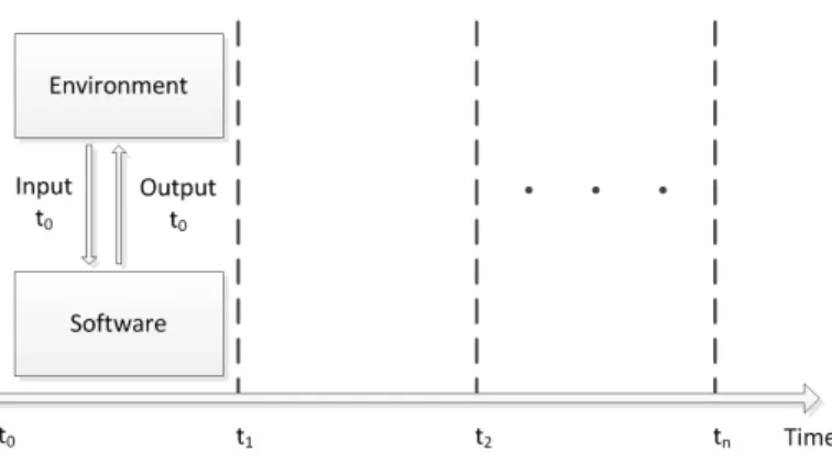
Synchronous languages vary in programming style, but are all based on the same computation model. This computation model is founded on the synchronous hypoth-esis. The synchronous hypothesis states that computation and communications are instantaneous from the point of view of logical time [5, 12]. Figure 2.1 illustrates the concept of synchronous computation.
Figure 2.1: Synchronous Software Operation
The synchronous model is fundamentally a time abstraction that assumes the hardware timing constraints are met by the system [11]. Astep in execution denotes a logical instant in time. Each step in a synchronous system is an ordered sequence consisting of the reception of inputs, the internal program computation, and the generation of output values. The execution of a synchronous program consists of a sequence of steps.
2.1.2
Synchronous Validation
The synchronous paradigm is suitable for automated validation due its inherent determinism. An overarching theme in automated validation of synchronous programs is the use of synchronous observers as established in [18]. By observer, it is meant a second program that monitors the runtime behavior of the program under test [14]. This approach is adequate for synchronous programs since communication among synchronous processes is a strict sequence of atomic steps that avoids the problem of non-determinism in the interleaving of asynchronous processes [14].
More specifically with reactive systems, the synchronous observers are an envi-ronment property observer and a safety property observer that work in conjunction with a test generator. The purpose of an environment observer is to ensure that only relevant test cases are produced by the test case generator. In practice, this is typically implemented by specifying environment test profiles. Given a sequence of test cases, the purpose of a safety observer is to ensure the system behavior meets specified safety properties; therefore, rather than explicitly providing a test suite, a collection of invariant safety properties must be specified.
2.2
SIGNAL
SIGNAL is a polychronous (i.e. synchronous, multi-clock) dataflow specification language. Polychronous components allow multiple clock rates, and are therefore suitable for describing distributed systems [13, 12]. In a dataflow description of a program, each concurrent statement can effectively have a different clock by having dependencies on different signals. This concept is often found in hardware description languages, where a statement is updated only when an event, such as a rising-edge,
Construct Type Syntax Parallel Composition (| P | Q |)
Restriction P where x
Assignment y := x
y := F(x1,x2,...,xn) Delay Assignment y := x $ init c Sampling Assignment y := x when z
Merging Assignment y := x default z
Table 2.1: Assignment Statements in SIGNAL
occurs on one of its signals. At each step in the execution of a SIGNAL program, each signal can be either present or absent [11].
SIGNAL was developed in Rennes, France at the Research Institute in Computer Science and Random Systems (IRISA) [11]. A SIGNAL compiler is included in the Polychrony toolset which is freely distributed by the ESPRESSO team at IRISA [28]. A commercial implementation of Polychrony, called RT-Builder, is supplied by the company GeenSoft for industrial scale projects [20, 11].
2.2.1
Primitive Language Constructs
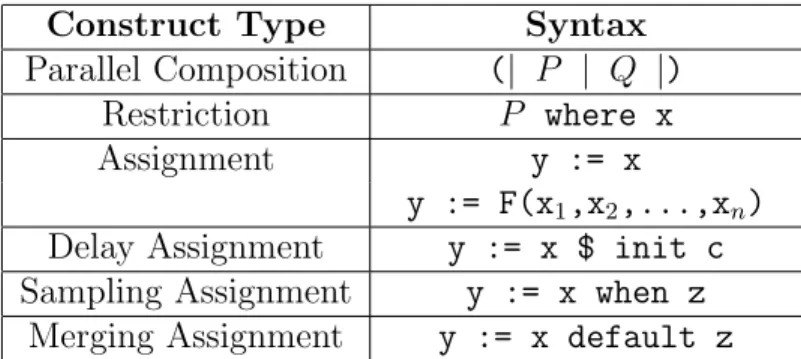
The SIGNAL primitive language constructs are briefly introduced here, and an example of the SIGNAL specification for a cruise control system is provided in the fol-lowing section. For a complete guide to the SIGNAL language, the reader is referred to [6]. The primitive language constructs of SIGNAL are summarized in Table 2.1. The individual statements that make up a program in SIGNAL are added through parallel composition. The parallel composition of P and Q means that both state-ments execute concurrently. In a SIGNAL program, a subprocess declaration is done
by using a restriction statement. The restriction statement declares x as being con-tained in P.
A concurrent assignment statement will assign the current step value of the signal x to the signaly. A delay assignment is much like a concurrent assignment, but with the inclusion of a delay operation. The delay operator “ $ ” is used to assign the previous-step value of xtoy. The sampling assignment can be used to assign a value to y when a given signal x is present and true or an expression is logically true. A merge assignment can be used to assign the value of x toy when x is present, or the value of z toy when x is absent and z is present.
2.2.2
Example: A Cruise Control System
A cruise control system is incrementally introduced in this section to provide an example of a SIGNAL program. The full program listing is provided in Appendix A. The cruise control system is further used in chapter 4 as the system-under-test for an example of a validation session in SAGA. For sake of clarity, this example provides a simple abstraction of an actual cruise control. The system is simplified by using the output signalsthrottleand brakeas Boolean assertions to control the vehicle speed differential. Furthermore, the system is restricted to a single-clocked specification, where all signals share the same clock. A diagram of the cruise control system is presented in Figure 2.2.
The diagram illustrates the system inputs and outputs which constitute the cruise control interface. Listing 2.1 shows the corresponding interface specification in SIG-NAL. These statements are the preamble to the body description of the system. The
Figure 2.2: Cruise Control System Diagram
set input is used to activate cruise control, and the cancel input is used to deac-tivate cruise control. The speed inc and speed dec inputs are used to increment and decrement, respectively, the cruise control speed. The input speed is an integer value provided to the cruise control system which represents the current reading from a speed sensor in the vehicle. The outputs throttle and brake are used by the cruise control system to increase or decrease, respectively, the speed of the vehicle. Finally, the ctrl on dispoutput is used to indicate whether cruise control is active or inactive. 1 p r o c e s s c r u i s e C o n t r o l = 2 ( % i n p u t s % 3 ? i n t e g e r s p e e d ; % s p e e d s e n s o r % 4 b o o l e a n set , % t u r n ON c r u i s e c o n t r o l % 5 cancel , % t u r n OFF c r u i s e c o n t r o l % 6 s p e e d _ i n c , % i n c r e a s e c r u i s e s p e e d % 7 s p e e d _ d e c ; % d e c r e a s e c r u i s e s p e e d % 8 % o u t p u t s % 9 ! b o o l e a n t h r o t t l e , % t h r o t t l e c o n t r o l % 10 brake , % b r a k e c o n t r o l % 11 c t r l _ o n _ d i s p ; % c o n t r o l i n d i c a t o r % 12 )
The internal variables control onand cruise speed are declared in Listing 2.2. Thecontrol onvariable is used to store the current status of the system. A value of
true forcontrol on indicates the cruise control system is active. Thecruise speed variable is used to store the speed at which the cruise control system must maintain the vehicle.
1 w h e r e % l o c a l v a r i a b l e s %
2 b o o l e a n c o n t r o l _ o n ; % c r u i s e c o n t r o l s t a t e % 3 i n t e g e r c r u i s e _ s p e e d ; % c r u i s e c o n t r o l s p e e d % 4 end % c r u i s e C o n t r o l %
Listing 2.2: Cruise Control: Internal Variables
The body of the program is presented in Listing 2.3. It is important to keep in mind that assignment statements are executed concurrently within a step. The statement in line 1 assigns a value to the internal variable control on of true when set is true, else false when cancel is true; otherwise, it maintains its previous-step value control on$. The output signal ctrl on disp in line 5 reflects the value of the internal variable control on.
1 ( | c o n t r o l _ o n := ( t r u e w h e n set ) 2 d e f a u l t ( f a l s e w h e n c a n c e l ) 3 d e f a u l t ( c o n t r o l _ o n $ i n i t f a l s e ) 4 5 | c t r l _ o n _ d i s p := c o n t r o l _ o n 6 7 | c r u i s e _ s p e e d := ( s p e e d w h e n set ) d e f a u l t ( ( c r u i s e _ s p e e d $ i n i t 0) +1 w h e n s p e e d _ i n c ) 8 d e f a u l t ( ( c r u i s e _ s p e e d $ i n i t 0) -1 w h e n s p e e d _ d e c ) 9 d e f a u l t ( c r u i s e _ s p e e d $ i n i t 0 ) 10 11 | t h r o t t l e := ( f a l s e w h e n ( ( s p e e d >= c r u i s e _ s p e e d ) and c o n t r o l _ o n ) )
12 d e f a u l t ( t r u e w h e n (( s p e e d < c r u i s e _ s p e e d ) and c o n t r o l _ o n ) ) 13 d e f a u l t f a l s e 14 15 | b r a k e := ( f a l s e w h e n (( s p e e d <= c r u i s e _ s p e e d ) and c o n t r o l _ o n ) ) 16 d e f a u l t ( t r u e w h e n ( ( s p e e d > c r u i s e _ s p e e d ) and c o n t r o l _ o n ) ) 17 d e f a u l t f a l s e 18 | )
Listing 2.3: Cruise Control: Signal Assignments
Line 7 provides that when set is asserted, the current value of speed is saved in the internal variablecruise speed; else if speed inc orspeed dec are asserted, the value of cruise speedis incremented or decremented, respectively, by one unit. The default value of cruise speed is otherwise its previous-step valuecruise speed$.
For cruise control to effect a speed increase, the output signal throttle is used. Line 11 states throttle will only be true when control on is active and the value of input signal speed, the current vehicle speed, is below cruise speed. The output signal brake is also only true when control on is active, but instead requires the speed to be greater than cruise speed.
CHAPTER 3
AN OVERVIEW OF SAGA
3.1
SAGA Defined
The SIGNAL Auto-Generated Assayer (SAGA) is an automated validation tool for synchronous reactive embedded systems. It is built to work with SIGNAL programs as part of an investigation of the automatic testing of synchronous reactive systems. The main purpose of SAGA is to shift the testing effort associated with critical systems from the onerous procedure of manually creating individual test cases to reasoning about the safety and environment properties of a system.
SAGA provides a framework with which, given the current-day computational resources and a properly specified environment, a system may be simulated through multiple lifetimes of operation under varying scenarios; hence, rather than using an exhaustive exploration, SAGA provides the means for conducting a smart search in the practically infinite state space of a modern non-trivial application.
3.2
Approach
When a SIGNAL program is compiled, source code is generated in either C, C++ or Java code by the Polychrony Environment [11]. The generated code can be used for simulation or deployment purposes. SAGA works with the simulation executable
program compiled from C code. The diagram in Figure 3.1 illustrates the general architecture of SAGA. Given the executable program of the system-under-test, only information about the system interface concerning the inputs and outputs must be furnished to SAGA. This allows for black-box testing where no knowledge is required of the system code, which may be proprietary or confidential. SAGA reads the interface information from a user-provided initialization file.
Figure 3.1: Architecture Diagram of SAGA
In addition to the initialization file, SAGA makes use of an environment descrip-tion file and a safety descripdescrip-tion file containing the environment and safety properties, respectively, specified by a user for a system. The properties in these files are written with SAGA-specific syntax. Complete with these files, SAGA can run a validation session of specified length. The length in a session is defined by the number of steps
(discrete logical instants) through which the system must be elapsed. During each step, SAGA generates a set of inputs to the system-under-test in accordance with the environment properties and checks the corresponding system behavior against the safety properties.
Upon the completion of each session, a log is generated of the entire simulation. This log contains the values of the provided inputs and observed outputs at each step. If a safety violation was detected during the test, a warning is displayed on the standard output and the corresponding step at which the problem occurred is annotated in the log. The entire data set is formatted in a comma-separated values (CSV) file for ease of data manipulation in parsing or generation of visual graphs.
3.3
Environment Simulation
The SAGA simulated environment is generated in accordance to the user-provided environment description. The environment is reactive with the system-under-test and therefore also takes into account the past inputs and outputs. For this reason, the user may specify initial conditions to the system (initial I/O values). For data-direction clarity, the convention is used of referring to signals from the environment to the system-under-test as inputs, and signals from the system-under-test to the environ-ment as outputs. SAGA currently supports integer and Boolean data-types as input and output for environment simulation. For integer input generation, the user may specify a value range by setting max and min values. The default value range is the compiler-specific signed integer range. A linear constraint may also be set on the in-teger inputs, where a value may only increment or decrement by a single unit during each step.
It is important to note that since outputs are the response of the system-under-test to the simulated environment, only the generation of inputs to the system-under-test is controlled by SAGA. The overall behavior of the environment, i.e generated in-puts, is obtained from the collection of individually specified environment properties. To specify environment properties, the following four mechanisms which are incor-porated into SAGA may be used: explicit constraint, probability-based constraint, operational-profile, and pattern profile. These mechanisms make use of a variety of logical and relational operators, such as greater-than, less-than-or-equal-to, not-equal-to, etc. The mechanisms available, thoroughly detailed in Chapter 4, are introduced here:
• Explicit Constraint: a constraint between either a) an input and an output signal, b) two input signals, or c) an input signal and a value. The type of constraint is defined by the logical or relational operator used. The explicit constraint is satisfied by SAGA at every step in the simulation, meaning appro-priate values are assigned to the input signal(s) so as to make the constraint true. For example, when an explicit constraint relating an input to an output is declared, such asinput1 <output1, SAGA satisfies this condition by assigning a value toinput1 that is less than the value of output1.
• Probability-based Constraint: a constraint defined similarly to an explicit con-straint, but rather than being satisfied at every step, is only satisfied on a specified probability bias. The specified probability biasP, a real number con-tained in [0,1], corresponds to the probability of an associated constraint C
being satisfied during the current step in simulation. It holds therefore, that the logical negation of the associated constraint,¬Cis satisfied on a 1−P basis.
For example, a probability-based constraint such as P ( input1 < output1 ) = 0.75 states that during any given step, there is a 75% probability of input1 being less than output1 and hence a 25% probability of input1 being greater than or equal to output1.
• Operational Profile: a reaction to a specified system event. The system event is denoted as an enter-condition, which is a propositional statement about the values of the previous-step signals. Given the enter-condition to an operational profile is true, then an associated constraint is satisfied on a specified probabil-ity bias. An operational profile is a probabilprobabil-ity-based constraint which becomes active if its enter-condition is true. The associated constraint condition is sat-isfied in the current step. For example, OP input1 = true − > P( input1 = true ) = 0.85 END OP means that if the value of input1 was true in the previous step (i.e. the enter-condition is true), then current step value of input1 has an 85% probability of being true. If the enter-condition is false, no assertion is made about the current value of input1. It is of special importance to note, as this example demonstrated, that an enter-condition refers to the previous step I/O values, and the constraint which must be satisfied pertains to the current step values.
• Pattern Profile: a sequence of reactions to a specified system event. Given the enter-condition of a pattern profile property evaluates to true, the first con-straint in a sequence of probability concon-straints is satisfied on a specified prob-ability bias. On the following execution step, the next probprob-ability constraint is likewise satisfied; therefore, each constraint in a pattern has a its own specified
probability bias. The pattern exits once a constraint is not satisfied (i.e. when a probability evaluates to false). After exiting, the enter-condition must once again be true for the pattern to be re-entered. An example pattern profile is as follows,
PATTERN output3 = 100−>P( input2 = 2 ) = 0.95−>P( input2 = 4 ) = 1−> P( input2 = 8 ) = 0.9 END PATTERN. Givenoutput3 had a value of 100 in the previous step, there is a 95% chance input2 will be given a value of 2 in the current step. Subsequently, input2 is guaranteed (100% probability) to be assigned the value 4 in the following step and has a 90% chance of having a value of 8 two steps ahead. The probabilities assigned in a pattern profile are viewed as independent events relating to the current step of execution, consequently the actual probability of satisfying the last constraint in a sequence is in reality a compound probability (trivially, the product of all preceding probabilities).
Altogether, the validation methods in conjunction with relational operators allow for a wide-range of specifications which may be tailored to different types of systems and testing goals. A proper environment description in which a combination of com-mon patterns of operation that occasionally deviate from typical behavior allows for an extensive exploration of the relevant state space of a system. Furthermore, the environment properties may be written so as to conduct specialized tests to search around system thresholds and boundary conditions in order to increase robustness.
3.4
Safety Validation
During each step in a simulation, the safety validation phase occurs after the system-under-test has reacted to the SAGA generated inputs. The validation process in SAGA consists of checking the execution of the system against the user specified safety properties. Similar to the environment description, the safety description is a collection of individual properties that together encompass the overall safe behavior of a system. The safety properties must therefore be written so as to express the conservative set of states in which nothing bad happens.
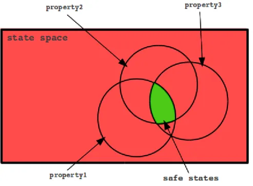
In SAGA, safety properties are written as invariant propositional statements on the inputs and outputs of a system with the use of logical and mathematical relational operators. Each property must be true throughout the entire execution for a system to be safe. The safe behavior of a system is therefore contained in the intersection of the set of states described by each safety property, as is illustrated in Figure 3.2.
Although, the use of temporal logic is not fully incorporated into SAGA valida-tion, a delay operator $ allows invariant properties to be set between current and previous-step signals. The delay operator $, inherited from the Signal language, al-lows one to refer to the previous-step value of a signal. It can be used by appending it to an input or output signal as such: input3$. This operator can therefore be used to include temporal aspects into a safety property.
Individual safety properties may be specified as single or multiple nested propo-sitional statements by using logical operators and parenthesis. For example, using Boolean data-type signals output1, and output2 a property could be written us-ing logical operators as follows, SAFE output1 OR output2 END SAFE. The
Figure 3.2: Safety Properties and the System State Space
property states that eitheroutput1 oroutput2 must always be true. A second prop-erty could be specified using a integer data-type signal output3, a relational opera-tor, and the delay operaopera-tor, in the following manner, SAFE output3 > output3$ END SAFE. This property checks that the current value of output3 is always greater than its previous step value output3$. With proper use of parenthesis and logical connectives, individual properties may be as extensive as necessary. By nest-ing statements and usnest-ing basic operators, a more complex property may be written as follows, SAFE ( output3 > 100 ) AND ( ( output1 = output1$ ) OR ( input1 ≥ output3 ) ) END SAFE. The requirements this property imposes on a system, is that output3 must be greater than 100 and either the value of output1 is equal to its past value or input1 is greater-than-or-equal to output3. Generally,
a safety violation is detected by SAGA during the validation phase when any one of the properties, such as the ones presented here, in a safety description evaluate to false during any given step in a simulation.
The aim of a well-written safety description must be to conservatively restrict the system to trusted behavior. It may be challenging to produce safety properties at times because it is not always evident what kind of system behavior can cause prob-lems; however, even when SAGA does not detect an error condition due to lack of a thorough specification, an inspection of the simulation log may in many cases reveal program bugs. Furthermore, engagement in the activity of creating safety properties by the system designer can in itself lead to the discovery of system design errors or bugs.
CHAPTER 4
USING SAGA
4.1
Compiling and Running SAGA
SAGA is a console application that accepts the required specification files and optional flags as parameters to run a simulation. In order to install SAGA, it must first be compiled from source code. To compile the latest version of SAGA, a plain “make” command can be used on the makefile provided in the base directory of the source code folder. The makefile requires the GNU Compiler Collection (GCC). Upon compilation, an executable “SAGA” is generated in the base directory. This executable may be moved to the desired installation directory. SAGA may then be executed from its install directory as a console application using a UNIX shell. Upon running SAGA without providing parameters, the following help menu is displayed which explains the use of individual flags:
U s a g e :
S A G A [ f l a g s ] ... [ l e n g t h ] [ i n i t _ f i l e ] [ e n v _ f i l e ] [ s a f e _ f i l e ] D e s c r i p t i o n :
Run a v a l i d a t i o n s e s s i o n of l e n g t h [ l e n g t h ] for a s p e c i f i e d system , w h o s e I / O i n t e r f a c e is c o n t a i n e d in [ i n i t _ f i l e ]. The e n v i r o n m e n t is g e n e r a t e d w i t h r e s p e c t to the p r o p e r t i e s s p e c i f i e d in [ e n v _ f i l e ] and the s y s t e m is v a l i d a t e d w i t h r e s p e c t to the p r o p e r t i e s s p e c i f i e d in [ s a f e _ f i l e ]. The o u t p u t of the s e s s i o n is l o g g e d in a c o m m a s e p a r a t e d v a r i a b l e f i l e "[ s y s t e m n a m e ] _ t r a c e _ [ T I M E S T A M P ]. csv ". F l a g s : - v V e r b o s e m o d e . P r o v i d e s d e t a i l e d i n f o r m a t i o n a b o u t the s i m u l a t i o n . It is r e c o m m e n d e d to p i p e the o u t p u t of S A G A to a t e x t f i l e w h e n u s i n g v e r b o s e m o d e . An e x a m p l e e x e c u t i o n w o u l d be of the f o r m a t : S A G A - v 100 i n i t . txt env . txt s a f e . txt > log . txt - i M a n u a l i n i t i a l i z a t i o n . A p r o m p t is p r o v i d e d to e n t e r i n f o r m a t i o n a b o u t the S y s t e m ( r a t h e r t h a n p r o v i d i n g [ i n i t i a l _ f i l e ] ) . - h e l p i n i t
P r o v i d e s i n f o r m a t i o n a b o u t the c o n t e n t s and f o r m a t of the i n i t i a l i z a t i o n f i l e as r e q u i r e d by S A G A .
- h e l p env
P r o v i d e s i n f o r m a t i o n a b o u t the c o n t e n t s and f o r m a t of the e n v i r o n m e n t d e s c r i p t i o n f i l e as r e q u i r e d by S A G A . - h e l p s a f e
P r o v i d e s i n f o r m a t i o n a b o u t the c o n t e n t s and f o r m a t of the s a f e t y d e s c r i p t i o n f i l e as r e q u i r e d by S A G A .
Listing 4.1: SAGA Help Menu
The file parameters [init_file], [env_file], [safe_file] above refer to the directory location of the initialization, environment, and safety files, respectively. The test length parameter, [length], specifies the number of steps (discrete logical instants) in the simulation. As an example, the configuration of SAGA for a validation session of the cruise control system introduced in Section 2.2.2 is used in this and following sections. To execute SAGA for the purpose of running a validation session on the cruise control system, the following command is used:
SAGA -v 50 cruiseControl_init.txt cruiseControl_env.txt cruiseControl_safe.txt
In the above command, the flag “-v” provides a verbose output to the standard output regarding the status of the simulation. The files cruiseControl_init.txt, cruiseControl_env.txt, and cruiseControl_safe.txt represent the correspond-ing initialization, environment, and safety descriptions located in the local SAGA directory and used for the cruise control system. Each file is presented in the follow-ing sections.
4.2
Specifying Initialization
In order to run a simulation, SAGA requires interface information about the system-under-test. The interface information can be provided to SAGA through an initialization file or manually through a prompt by using the -i flag. Since the prompt for manually entering information is self-explanatory, only the initialization file format is presented here. The initialization file requires information about the inputs and outputs of the system-under-test, and allows the user to specify system initial conditions and set options regarding environment control.
4.2.1
File Format
The initialization file must contain the complete interface information of the system-under-test regarding the name of the executable program and its input and output signals. In addition, an initial value can be specified for any I/O signal in the file to start a simulation from a predetermined state. Integer input signals must be specified with additional attributes including min and max values, as well as whether
or not they should be linearly constrained. Forlinearly constrained integer signals, the environment will only generate values within single-unit increments or decrements. The information is parsed from the file in a specific order and therefore the file must be formatted properly.
The required information and ordering is as follows:
1. The name of the executable program for the system-under-test. 2. The number of Boolean input signals.
3. The number of Boolean output signals. 4. The number of integer input signals. 5. The number of integer output signals.
6. A list of the Boolean input names and initial values, for example: Boolean_input 0
7. A list of the Boolean output names and initial values, for example: Boolean_output 1
8. A list of the integer input names, their corresponding initial, min, and max values, and whether or not ( 1 or 0) they should be linearly constrained, for example:
integer_input 35 0 400 1
9. A list of the integer output names and their corresponding initial values, for example:
integer_output 5
In the initialization file, tab and newline characters are effectively treated the same as space characters and can be used as delimiters for organization. The data provided must be consistent throughout; therefore the number of signals of each data-type
specified, must match an equivalent count of signal names. If there any inconsistencies in the file are detected, SAGA will produce a relevant error and quit. For any value in the file, the place holder “x” can be used to generate default values. By default, integer input signals have min and max values equivalent to the corresponding compiler-specific min and max signed integer values, and are not linearly constrained. For any signal, its default initial condition is randomly chosen. By random, it is meant a uniform probability of its possible values.
4.2.2
Example: Cruise Control Initialization
A sample configuration for the cruise control system with the interface information provided in Section 2.2.2 is as follows:
1 % -2 % c r u i s e C o n t r o l -3 % -4 5 % N a m e of system - under - t e s t 6 c r u i s e C o n t r o l 7 8 % N u m b e r of B o o l e a n i n p u t and o u t p u t s i g n a l s 9 % [ No . i n p u t ] [ No . o u t p u t ] 10 4 3 11 12 % N u m b e r of I n t e g e r i n p u t and o u t p u t s i g n a l s 13 % [ No . i n p u t ] [ No . o u t p u t ] 14 1 0 15 16 % N a m e s of B o o l e a n s i g n a l s ( m u s t m a t c h SUT s i g n a l n a m e ) and i n i t i a l v a l u e s 17 % [ n a m e ] [ i n i t _ v a l u e ] 18 set 0 % i n p u t s 19 c a n c e l 0 20 s p e e d _ i n c 0 21 s p e e d _ d e c 0 22 t h r o t t l e 0 % o u t p u t s 23 b r a k e 0
24 c t r l _ o n _ d i s p 0 25
26 % N a m e s of I n t e g e r s i g n a l s ( m u s t m a t c h SUT s i g n a l n a m e ) , i n i t i a l v a l u e
27 % m i n i m u m value , m a x i m u m value , and l i n e a r c o n s t r a i n t
28 % [ n a m e ] [ i n i t _ v a l u e ] [ m i n _ v a l u e ] [ m a x _ v a l u e ] [ l i n e a r ]
29 s p e e d 30 0 300 1 % i n p u t
Listing 4.2: Contents of “cruiseControl init.txt”
The initialization file presented above follows the formatting specified in Section 4.2.1. The Boolean valuestrueandfalseare represented using 1 and 0 respectively. Furthermore, comments are included to help organize the file. The percent charac-ter % is universally used by SAGA to denote a comment; therefore, any characcharac-ters following the percent character in a line are ignored.
4.3
Specifying the Environment
The environment description is a collection of properties which are used to describe the behavior of the system environment. The different types of properties which can be used are described in Section 3.3. In this section, the syntax of each type of property is detailed and examples of properties as applied to the environment description of the cruise control system are provided.
4.3.1
Syntax
The syntax is formally introduced in Backus-Naur Form (BNF). The four mech-anisms for describing the environment properties are defined as follows:
Explicit Constraint
signal ::= in signal | out signal | prev signal out signal ::= output signal
in signal ::= input signal
prev signal ::= in signal$ | out signal$
value ::= Boolean | integer
operator ::= logical| relational
Probability-based Constraint
probability constraint ::= P( explicit constraint ) = probability probability ::= 0≤real≤1
Operational Profile
operational profile ::= OP enter condition -> probability constraint END OP
enter condition ::= prev signal operator ( prev signal | value )
Pattern Profile
pattern ::= PATTERN enter cond -> prob const lst END PATTERN
prob const lst ::= probability constraint |probability constraint -> prob const lst
The available operators are provided in Table 4.1. In general, relational operators can be used on integer data-type signals, while logical operators can be used on Boolean data-type signals or with expressions which evaluate to a Boolean value. The “+” and “−” are special operators used increment or decrement an integer signal by
Comments Operator Type Equality = Relational/Logical Difference != Relational/Logical Disjunction OR/|| Logical Conjunction AND/&& Logical Greater Than >,>= Relational
Less Than <,<= Relational
Increment + Arithmetic
Decrement - Arithmetic
Table 4.1: SAGA Operators
a specified value. They effectively add or subtract the value of the right expression to/from the signal on the left side.
When generating the environment during each step, SAGA ensures that every input signal is assigned a value. Given an environment description is composed of one or more properties, individual signals can be used in more than one property. Priority is given to satisfying signals in properties in the following order: pattern profile, operational profile, probability-based constraint, and explicit constraint. When a signal is used in two properties of the same type, the first property in top-down order in the description file is used to generate a value for the signal. When a signal which has already been assigned a value is used in a property that relates it to a different signal which has not been assigned a value, the property is satisfied by only assigning a new value to the second signal, or ignored if the constraint is not satisfiable. Furthermore, when a signal is not used in any one property, by default it is assigned a random value within its defined range.
4.3.2
Example: Cruise Control Environment
The following excerpt provides properties used to describe a realistic environment for the cruise control system.
1 % S p e e d up w h e n t h r o t t l e is a c t i v a t e d 2 OP t h r o t t l e = 1 - > P ( s p e e d > s p e e d $ ) = 1 E N D _ O P 3 4 % D r i v e r i n c r e a s e s s p e e d m o r e o f t e n w h e n in c r u i s e c o n t r o l 5 P ( s p e e d _ i n c = 1 ) = 0 . 6 0 6 P ( s p e e d _ d e c = 1 ) = 0 . 2 0 7 8 % If u s e r d e c r e a s e s speed , m o r e l i k e l y to c o n t i n u e d e c r e a s i n g 9 OP s p e e d _ d e c $ = 1 - > P ( s p e e d _ d e c = 1 ) = 0.7 10 11 % S p e e d s e n s o r f a u l t 12 P ( s p e e d > 9 0 0 0 ) = 0 . 0 1
Listing 4.3: Excerpt from “cruiseControl env.txt”
In line 2 of Listing 4.3, we observe a property of the environment which states that when the Boolean output throttle is true, the integer input speed will increase in value i.e. have a greater value thanspeed$, its previous-cycle value. The environment models the theoretical driver as someone who tends to increase their speed more often when they are using the cruise control feature of the automobile, as is illustrated in lines 5 and 6, by assigning a higher probability to thespeed incinput signal; however, the property in line 9, accounts for the fact that if a driver decreases speed once, they will more than likely continually do so. Finally, the property in line 12 states there is a 1% probability that the value of speed is over 9000, which effectively simulates a sensor glitch with a discontinuous jump to a large, unrealistic value.
4.4
Specifying Safety Validation
The safety description is a collection of properties that specify the safe behavior of a system. These properties are checked at every step in a simulation. A violation of safety in the system is detected when any of the properties evaluates to false. This concept is more thoroughly described in Section 3.4.
4.4.1
Syntax
A safety property can be defined by a single expression or by multiple expressions connected by well-formed parentheses and logical operators as follows:
safety property ::= SAFE first expression END SAFE
first expression ::= expression operator expression
expression ::= signal | value | “ ( ” expression operator expression “) ”
signal ::= input signal | output signal | prev signal out signal ::= output signal
in signal ::= input signal
prev signal ::= in signal$ | out signal$
value ::= Boolean | integer
operator ::= logical| relational
This format allows for basic propositional statements, as well as more complex statements containing several nested parenthesis. A current limitation on the syntax is that each nested expression must consist of three arguments, where the the middle
argument must be a operator and the leftmost and rightmost arguments can be a
signal, value, or a subsequent nestedexpression.
4.4.2
Example: Cruise Control Safety
The following Listing provides properties taken from the safety description used with the cruise control system.
1 % T h r o t t l e or b r a k e c o n t r o l s h o u l d not be a c t i v e if c r u i s e c o n t r o l is OFF 2 S A F E ( ( t h r o t t l e or b r a k e ) and ( c t r l _ o n _ d i s p = 0 ) ) = 0 E N D _ S A F E 3 4 % B r a k e and t h r o t t l e s h o u l d not be a c t i v a t e d s i m u l t a n e o u s l y 5 S A F E ( b r a k e = 0 ) or ( t h r o t t l e = 0 ) E N D _ S A F E 6
7 % W h e n c a n c e l is true , cruise , t h r o t t l e , and b r a k e c o n t r o l s h o u l d be OFF
8 S A F E ( ( c a n c e l = 1 ) and ( ( ( c t r l _ o n _ d i s p = 0) and ( t h r o t t l e = 0 ) ) and ( b r a k e = 0 ) ) ) or ( c a n c e l = 0 ) E N D _ S A F E
Listing 4.4: Excerpt from “cruiseControl safe.txt”
A very basic expectation of a cruise control system is declared in line 2 of List-ing 4.4, which states that neither throttle or brake should be asserted while the cruise control is OFF, as is indicated by ctrl on disp, the control state display. Furthermore, the property in line 5 stipulates that brake and throttle should not be asserted simultaneously. The last property in line 8 states that when cancel is asserted, meaning the driver wishes to turn OFF cruise control, the system responds accordingly.
4.5
Interpreting Results
The output of every validation session in SAGA is logged in a CSV file named [system name] trace [time stamp].csv. This file contains the values generated and received at every step. When a safety violation is detected, a warning is displayed on the standard output and the log is annotated on the corresponding step.
Given the initialization, environment, and safety descriptions provided for the ex-ample cruise control system, the results of the first ten steps are displayed in Figure 4.1. These values show that the set signal was asserted at logical time two and ef-fectively turned cruise control ON. Throughout the following steps, the speed inc signal is asserted, which in turn activatesthrottle and effects increases in speed.
Figure 4.1: Cruise Control Simulation Log
By plotting the values generated by SAGA for the speed signal, a visual repre-sentation of the system behavior is obtained in Figure 4.2. The figure is annotated
with key events from the simulation.
Figure 4.2: Speed Signal in Cruise Control
The visual representation of the data shows typical, expected operation of the cruise control; however, a warning on the standard display and an inspection of the simulation log yield a surprise on cycle #36 displayed in Figure 4.3. The detected error is apparent upon examination of the input and output signals. The problem, evident by the status display ctrl on disp, is that the system turned ON and re-mained ON, even though the cancel input was asserted.
Upon examination of the cruise control system Signal specification introduced in Section 2.2.2 the error points to the implementation of the local variablecontrol on
Figure 4.3: A Safety Violation
used to process the state of the system. The faulty code snippet is provided in Listing 4.5.
1 | c o n t r o l _ o n := ( t r u e w h e n set ) 2 d e f a u l t ( f a l s e w h e n c a n c e l ) 3 d e f a u l t ( c o n t r o l _ o n $ i n i t f a l s e )
Listing 4.5: Cruise Control: A Bug Exposed
The test case exposed that when set and cancel where simultaneously asserted, cancelwas ignored. Therefore, if a driver operating this system would have attempted to turn OFF cruise control and accidentally pressed bothsetandcancel, the system would have remained ON. This implementation is not correct with the desired safe specification of the system. Semantically, the root of the problem is the improper use of the default operator in the program. In Signal, thedefaultoperator gives priority to its left argument, and only if the left expression evaluates to false is the right expression evaluated. An appropriate correction in this example is to give cancel priority over set as is done in the altered code snippet in Listing 4.6.
1 | c o n t r o l _ o n := ( f a l s e w h e n c a n c e l ) 2 d e f a u l t ( t r u e w h e n set )
3 d e f a u l t ( c o n t r o l _ o n $ i n i t f a l s e )
CHAPTER 5
CASE STUDY: STEAM BOILER
5.1
Introduction
The purpose of this chapter is to demonstrate the effectiveness of the simulation and validation capabilities of SAGA as applied to a system of substantial complexity. To that end, a well-known verification problem, the steam boiler control specification [2], was chosen. This specification has been often used for the purpose of demonstrat-ing the application of formal methods to a real-life industrial application in order to unify scientific progress in the field with practices in industry [3]. The steam boiler problem, though most frequently used for examples of verification, was selected since its full specification is readily available and many in the target audience are familiar with it. The specification is used to develop an initial implementation of a steam boiler system with the SIGNAL programming language. Given the purpose of testing is to expose the presence of errors, not prove their absence, the goal in implementing the steam boiler is to provide a working example with which the effectiveness of the validation process in SAGA of exposing errors can be qualitatively assessed.
5.2
Steam Boiler Specification
A steam boiler program is a control application that moderates the level of water inside a steam boiler by turning water pumps ON and OFF. The control program must function properly; otherwise a quantity of water too high or too low could damage the steam boiler or the driven turbine. An informal specification for such a system constitutes the steam boiler specification problem presented in [2]. The case study program is implemented directly from the aforementioned text. A brief overview of the specification is provided here. For the complete specification details, the reader should refer to the original text. The SAGA files and the full program listing of the SIGNAL implementation of the steam boiler developed for this case study are provided in Appendix B. For ease of readability, the input and output signals in the implementation are consistent with the naming of the sent and receivedmessages of the original specification.
5.2.1
Overview
A diagram of the steam boiler environment is depicted in Figure 5.1. This diagram demonstrates the constraints of the control application, which are namely the water level limits and the available physical devices. The implemented values associated with each water level limit are presented in Table 5.1.
The steam boiler physical environment effectively consists of four pump units, a water release valve, a water level sensor, and a steam sensor. Each pump unit consists of a pump, which can be turned ON and OFF by the program, and a pump controller that provides information to the program regarding whether or not water is flowing through the pump. The program is informed of the current amount of water in the
Parameter Comment Value Unit C Maximal Capacity 150 liter
M1 Minimal Limit 20 liter
M2 Maximal Limit 130 liter
N1 Minimal Normal 60 liter
N2 Maximal Normal 90 liter
Table 5.1: Implementation Values of Physical Constants
steam boiler and the amount of steam being produced, by a water level sensor and a steam sensor, respectively. The water release valve is used by the program only during start-up in order to lower the amount of water to the desired initial level.
The steam boiler program can be modeled as a synchronous system since it must follow a five second cycle, denoted as a step, in which the reception of messages, analysis of information received, and response to messages must happen, in that order. A simplified diagram of the steam boiler program interface is presented in Figure 5.2. The input and output signals constitute the messages between the program and the physical units.
Figure 5.2: Steam Boiler Program Simplified Interface
The behavior of the steam boiler program is primarily determined by its current mode. The five possible modes of operation are the following:
• Initialization: The program begins in this mode from start-up. It awaits until the steam boiler is ready, and ensures the water level is initially within N1 and
N2 by opening the water release valve or activating a pump if necessary before starting.
• Normal: While in this mode, the program tries to maintain the water level closely within N1 and N2. The program remains in this mode while no faults
are detected in the physical units and the water level is not risking reachingM1 orM2.
• Degraded: In this mode, the program attempts to maintain a satisfactory water level given the presence of a fault on one of the physical units other than the water level sensor.
• Rescue: When the water level sensor has a fault, the program enters this mode. In this mode, the program attempts to maintain a satisfactory water level by taking into account the maximum physical dynamics of the system.
• Emergency stop: The program enters this mode when the water level is risking reachingM1 or M2, the external stopsignal was asserted, or a message trans-mission error is detected. In this mode, the program stops and the physical environment is responsible for taking appropriate actions.
5.2.2
Implementation Limitations
The steam boiler program was implemented with some assumptions and limi-tations. These choices where made in order to provide a simplistic model for the physical evolution of the system, and to accommodate the fact that SAGA currently only supports integer type numbers. The limitations are the following:
• Quantity measurements of liters are in whole units and are therefore represented by integers. These include the steam output and water level measurements.
• A working pump will deliver water at its constant rate of 0.2 ltrs/sec (i.e. 1 liter every 5 seconds) where 5 seconds represent one step. This represents the nominal capacity of each pump.
Program Mode mode Value Initialization 1 Normal 2 Degraded 3 Rescue 4 Emergency Stop 5
Table 5.2: Program Mode Corresponding to modeValues
• The system produces steam in discrete values (ltrs/step) directly related to the water level, as shown in Listing 5.4.
• The stop signal must only be asserted once, rather than three times in a row, for the program to go into emergency stop mode.
5.3
Validation
Given a complete system specification, the validation process in SAGA is a straight forward activity. The safety properties of a system can be directly implemented from the specification, and thus be done concurrently with system design. The afore-mentioned approach is taken in this case study. A large number of properties, each relating to a functional requirement or set of requirements, may be written to pro-duce a thorough validation. For brevity, only a handful of safety and environment properties are presented here. A following discussion on some of the nontrivial errors detected in the implementation is then provided.
5.3.1
From Specification to Safety Description
A set of safety properties that correspond to the specification are presented in Listing 5.1. As a reference, Table 5.2 provides the values corresponding to each pro-gram mode for the signalmodein the implementation. In line 1, the property declares that either the program is inemergency stopmode or thestopsignal is not true. This effectively states that the program should not be in a mode other than emergency stop if the stopsignal is asserted. The following property in line 3, provides that the program cannot be in normal mode if the water level has reached or surpassed the maximal or minimal limits. When a pump and pump controller do not have matching states, it constitutes an equipment failure and the program must respond accordingly; therefore, the property in line 5 states that if pump state1andpump ctrl state1do not have the same value, the program must be indegraded,rescue, oremergency stop
mode. This property is also applied to pumps 2,3, and 4 (not shown here). Finally, the properties declared starting at line 7 check for transmission failures by ensuring that the program acknowledges every message received that requires an acknowledgment.
1 S A F E ( m o d e = 5 ) or ( s t o p != 1 ) E N D _ S A F E 2 3 S A F E ( m o d e != 2 ) or ( ( l e v e l <= 130 ) and ( l e v e l >= 20 ) ) E N D _ S A F E 4 5 S A F E ( p u m p _ s t a t e 1 = p u m p _ c t r l _ s t a t e 1 ) or ( ( ( m o d e = 3 ) or ( m o d e = 4 ) ) or ( m o d e = 5) ) E N D _ S A F E 6 7 S A F E ( ( p u m p _ r e p a i r e d 1 $ == 1 ) and ( p u m p _ r e p a i r e d _ a c k 1 == 1 ) ) or ( p u m p _ r e p a i r e d 1 $ == 0 ) E N D _ S A F E 8 S A F E ( ( p u m p _ c t r l _ r e p a i r e d 1 $ == 1 ) and ( p u m p _ c t r l _ r e p a i r e d _ a c k 1 == 1 ) ) or ( p u m p _ c t r l _ r e p a i r e d 1 $ == 0 ) E N D _ S A F E 9 S A F E ( ( l e v e l _ r e p a i r e d $ == 1 ) and ( l e v e l _ r e p a i r e d _ a c k == 1 ) ) or ( l e v e l _ r e p a i r e d $ == 0 ) E N D _ S A F E
10 S A F E ( ( s t e a m _ r e p a i r e d $ == 1 ) and ( s t e a m _ r e p a i r e d _ a c k == 1 ) ) or ( s t e a m _ r e p a i r e d $ == 0 ) E N D _ S A F E
Listing 5.1: Steam Boiler Safety Properties
5.3.2
Environment Simulation
Two approaches are taken for simulating a test environment in this case study: (i) describing a realistic runtime environment, where the typical operation of the system under usual conditions can be inspected and (ii) describing a stress scenario in which threshold values are exceeded and boundary operating cases are observed. The two approaches are illustrated using portions of the steam boiler environment description and their associated result.
Typical Operation
For the purpose of simulating the typical operation of the system, the environment must be described so as to be correctly responsive to the system-under-test. This is achieved by ensuring that the output of the program effects an appropriate change in the environment. The properties in Listing 5.2 demonstrate this by assigning a high probability to providing the correct response when a pump is opened or closed. The response is the pump and pump controller state change according to the program action. 1 OP c l o s e _ p u m p 1 = 1 - > P ( p u m p _ s t a t e 1 == 0 ) = 0 . 9 5 E N D _ O P 2 OP c l o s e _ p u m p 2 = 1 - > P ( p u m p _ s t a t e 2 == 0 ) = 0 . 9 5 E N D _ O P 3 OP c l o s e _ p u m p 3 = 1 - > P ( p u m p _ s t a t e 3 == 0 ) = 0 . 9 5 E N D _ O P 4 OP c l o s e _ p u m p 4 = 1 - > P ( p u m p _ s t a t e 4 == 0 ) = 0 . 9 5 E N D _ O P 5 6 OP o p e n _ p u m p 1 = 1 - > P ( p u m p _ s t a t e 1 == 1 ) = 0 . 9 5 E N D _ O P 7 OP o p e n _ p u m p 2 = 1 - > P ( p u m p _ s t a t e 2 == 1 ) = 0 . 9 5 E N D _ O P
8 OP o p e n _ p u m p 3 = 1 - > P ( p u m p _ s t a t e 3 == 1 ) = 0 . 9 5 E N D _ O P 9 OP o p e n _ p u m p 4 = 1 - > P ( p u m p _ s t a t e 4 == 1 ) = 0 . 9 5 E N D _ O P 10 11 OP c l o s e _ p u m p 1 = 1 - > P ( p u m p _ c t r l _ s t a t e 1 == 0 ) = 0 . 9 5 E N D _ O P 12 OP c l o s e _ p u m p 2 = 1 - > P ( p u m p _ c t r l _ s t a t e 2 == 0 ) = 0 . 9 5 E N D _ O P 13 OP c l o s e _ p u m p 3 = 1 - > P ( p u m p _ c t r l _ s t a t e 3 == 0 ) = 0 . 9 5 E N D _ O P 14 OP c l o s e _ p u m p 4 = 1 - > P ( p u m p _ c t r l _ s t a t e 4 == 0 ) = 0 . 9 5 E N D _ O P 15 16 OP o p e n _ p u m p 1 = 1 - > P ( p u m p _ c t r l _ s t a t e 1 == 1 ) = 0 . 9 5 E N D _ O P 17 OP o p e n _ p u m p 2 = 1 - > P ( p u m p _ c t r l _ s t a t e 2 == 1 ) = 0 . 9 5 E N D _ O P 18 OP o p e n _ p u m p 3 = 1 - > P ( p u m p _ c t r l _ s t a t e 3 == 1 ) = 0 . 9 5 E N D _ O P 19 OP o p e n _ p u m p 4 = 1 - > P ( p u m p _ c t r l _ s t a t e 4 == 1 ) = 0 . 9 5 E N D _ O P
Listing 5.2: Following Program Orders
Furthermore, the water level is set to increase according the the number of active pumps in Listing 5.3. Since each pump has a throughput of 1 ltr/step, the water level must increase by 1 liter for each active pump at every step. The water level of the steam boiler is also affected by the quantity of exiting steam. The amount of water leaving as steam is subtracted from the water level in line 6. Finally, in line 8 when the water release valve is on, the water level is decreased at a constant rate of 4 liters/step. 1 OP p u m p _ s t a t e 1 = 1 - > P ( l e v e l + 1 ) = 0 . 9 9 E N D _ O P 2 OP p u m p _ s t a t e 2 = 1 - > P ( l e v e l + 1 ) = 0 . 9 9 E N D _ O P 3 OP p u m p _ s t a t e 3 = 1 - > P ( l e v e l + 1 ) = 0 . 9 9 E N D _ O P 4 OP p u m p _ s t a t e 4 = 1 - > P ( l e v e l + 1 ) = 0 . 9 9 E N D _ O P 5 6 P ( l e v e l - s t e a m ) = 1 7 8 OP v a l v e = 1 - > P ( l e v e l - 4 ) = 1 E N D _ O P