DSL Forum
Technical Report
TR-090
Protocol Independent Object Model
for Managing Next Generation ADSL
Technologies
For
Operations and Network Management Working Group
Editor: Rajesh Abbi, Alcatel
Date: December 2004
Abstract:
This document specifies a protocol independent object model for managing ADSL lines using the next generation ADSL technologies including ADSL2, ADSL2plus, and RE-ADSL.
Notice:
This Working Text represents work in progress by the DSL Forum and must not be construed as an official DSL Forum Technical Report. Nothing in this document is binding on the DSL Forum or any of its members. The document is offered as a basis for discussion and communication, both within and without the DSL Forum.
1 Background
During the past few years, standards have been developed for the next-generation of ADSL technologies. The following new flavors of ADSL technologies have now been standardized by the ITU-T:
• ADSL2 (G.992.3 [3]) • ADSL2lite (G.992.4 [4]) • ADSL2plus (G.992.5 [5])
These next-generation technologies have greatly enhanced the capabilities as well as flexibility offered by the initial set of ADSL standards (ADSL - G.992.1 [1], and ADSLlite - G.992.2 [2]).
The existing management model used to support earlier ADSL technologies is not adequate to address the needs of the next generation technologies. This document specifies a new protocol-independent object model to address these needs.
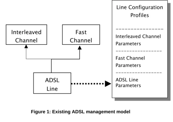
2 Existing management framework
The existing management framework was developed to address the needs of the initial set of ADSL technologies (G.992.1 and G.992.2). This framework was based on the object model shown in Figure-1.
ADSL Line Interleaved
Channel ChannelFast
Line Configuration Profiles ---Interleaved Channel Parameters ---Fast Channel Parameters ---ADSL Line Parameters
This object model addresses the needs of the existing ADSL technologies in a simple and efficient manner.
3 Needs of the next generation ADSL technologies
The next generation ADSL technologies support improved performance as well as flexibility to meet the needs of emerging broadband services like voice, video etc. They also support many new features that offer the operator a greater degree of control over the performance and behavior of the transmission lines.
Unfortunately, this enhanced capability comes at the cost of additional complexity to the management infrastructure.
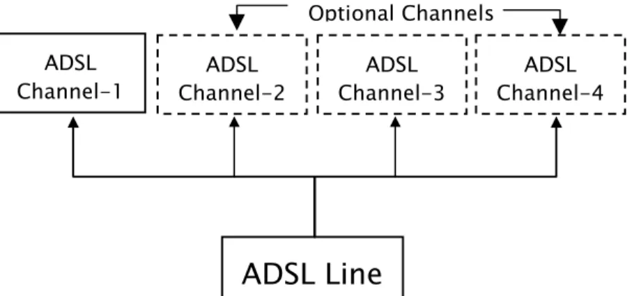
One of the major impacts is in the area of bearer channels. While original ADSL technologies supported a simple and fixed channel arrangement (Fast,
Interleaved, or both), the new standards allow a flexible configuration of up to four generic channels that can be independently configured with respect to latency. This is illustrated in Figure-2.
ADSL Line
ADSLChannel-1 Channel-2ADSL Channel-3ADSL Channel-4ADSL
Optional Channels
Figure 2: Bearer channel arrangement in the next generation ADSL technologies
Other changes introduced by the next generation ADSL technologies in terms of operations and management include additional configuration options in the following areas:
• Configurable power management timers • Spectrum / PSD control
• Messaging overhead control
• Impulse noise protection and BER control
The requirements for managing the next generation ADSL technologies are captured in the revised draft of ITU-T G.997.1 [6].
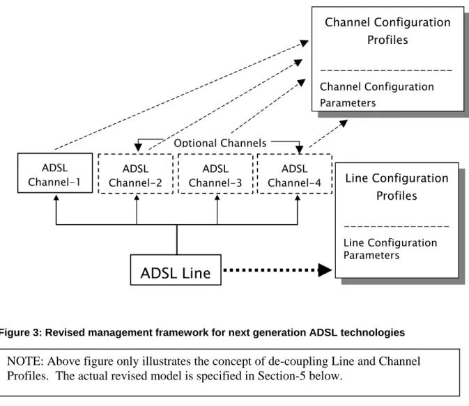
4 Revision of ADSL management framework
The current ADSL management model is based on the simple management framework shown in Figure-1. It is clearly not adequate to address the needs of the next generation ADSL technologies as illustrated in Figure-2. Moreover, the increasing number of configuration options for ADSL bearer channels result in a very large number of parameter combinations that cannot be managed easily in a monolithic profile.
One way to address this problem is by de-coupling bearer channel parameters from the ADSL line parameters into independent profiles. This would allow the necessary channel flexibility while maintaining the benefits of a profile-based model. This approach is illustrated in Figure-3.
ADSL Line
ADSLChannel-1 Channel-2ADSL Channel-3ADSL Channel-4ADSL
Optional Channels Line Configuration Profiles ---Line Configuration Parameters Channel Configuration Profiles ---Channel Configuration Parameters
Figure 3: Revised management framework for next generation ADSL technologies NOTE: Above figure only illustrates the concept of de-coupling Line and Channel Profiles. The actual revised model is specified in Section-5 below.
5 Revised ADSL Managed Object Model
The revised ADSL management framework defined in the previous section requires a new object model. This section specifies the revised object model in a management-protocol independent manner. This management model will be used for developing management-protocol-specific object definitions.
This specification is based on the revised list of managed objects per DSL Forum TR-066 [13] and ITU-T G.997.1 [6]. The object model in this specification only specifies the structure of the managed objects, the detailed parameter definitions and their access mode (read-only vs read-write) is specified in G.997.1.
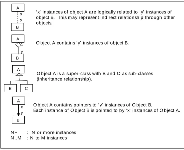
Figure-4 illustrates notations used in this specification for illustrating the object model.
A y x B
‘ x’ instances of object A are logically related to ‘ y’ instances of object B. This m ay represent indirect relationship through other objects.
A y B
O bject A contains ‘ y’ instances of object B.
1
A
B
O bject A is a super-class with B and C as sub-classes (inheritance relationship). C A y x B
O bject A contains pointers to ‘ y’ instances of O bject B.
Each instance of O bject B is pointed to by ‘ x’ instances of O bject A.
N + : N or m ore instances N ..M : N to M instances
5.1 Configuration Management
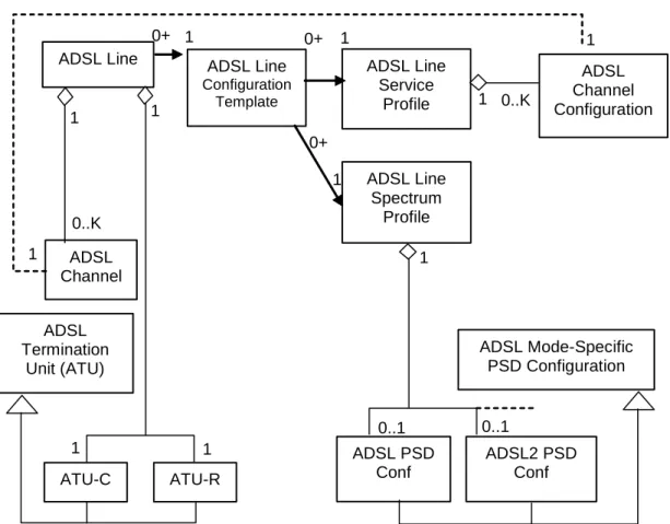
Figure-5 provides an overview of the object model of objects used for configuration management of ADSL lines.
ADSL Line ADSL Channel 1 0..K ADSL Line Service Profile ADSL Line Spectrum Profile ADSL Channel Configuration 1 0..K 0+ 1 1 1 1 ADSL Termination Unit (ATU) 1 ATU-C ATU-R 1 1 ADSL PSD Conf ADSL2 PSD Conf ADSL Line Configuration Template 0+ 1 0+ 1 ADSL Mode-Specific PSD Configuration 0..1 0..1
K : Maximum number of Channels per ADSL Line
Figure 5: Revised Managed Object Model - Configuration Management
5.1.1 ADSL Line
The ADSL Line object represents an individual physical transmission line and its associated parameters and states.
Following attributes are supported by the ADSL Line object:
¾ Pointer to ADSL Line Configuration Template
¾ Pointer to ADSL Line Threshold Template
¾ Power Management State Forced (PMSF)
¾ Loop Diagnostics Mode Forced
¾ ADSL Transmission System
¾ Success/Failure Cause
5.1.2 ADSL Channel
The ADSL Channel object represents an individual logical transmission channel over the ADSL Line and its associated parameters and states.
Following attributes are supported by the ADSL Channel object:
¾ Channel Number (Numeric ID for a channel in a Line – 1 to K)
One or more instances of ADSL Channel object may be supported by an ADSL Line Object.
5.1.3 ADSL Termination Unit (ATU)
An ADSL Termination Unit object represents an ADSL Modem at either end of the ADSL Line. The ATU object only represents a super-class that cannot be instantiated. It has two sub-classes that are instantiated - ATU-C (Central Office modem), and an ATU-R (Remote modem). The ADSL Line is always terminated by an ATU-C at the central office and an ATU-R at the remote subscriber
location.
Following attributes are supported for ADSL Termination Units:
¾ ATU G.994.1 Vendor ID
¾ ATU System Vendor ID
¾ ATU Version Number
¾ ATU Serial Number
¾ ATU Self-Test Result
¾ ATU ADSL Transmission System Capabilities
¾ Current 15-minute Interval Elapsed Time (0 to 900 sec)
¾ Number of previous 15-minute Intervals (0 to N)
¾ Number of previous invalid 15-minute Intervals (0 to N)
¾ Current 1-day Interval Elapsed Time (0 to 86400 sec)
¾ Number of previous 1-day Intervals (0 to M)
¾ Number of previous invalid 1-day intervals (0 to M)
5.1.4 ADSL Line Configuration Template
The ADSL Line Configuration Template is the object representing a complete configuration for an ADSL Line. This is similar to the ADSL Line Configuration Profile object in the older ADSL model. The template simply contains pointers to specific ADSL Line Service Profile and ADSL Line Spectrum Profile instances.
The ADSL Line Configuration Template object supports following attributes:
¾ Pointer to ADSL Line Service Profile
¾ Pointer to ADSL Line Spectrum Profile
5.1.5 ADSL Line Service Profile
The ADSL Line Service Profile is the object containing all ADSL service specific configuration parameters for a line. Any number of ADSL Lines can be
provisioned to use a particular ADSL Line Service Profile. It ensures that all lines sharing the Profile will be provisioned identically with respect to the parameters associated with the Profile.
The ADSL Line Service Profile object supports following attributes:
¾ Profile Name
In addition, it logically contains one or more instances of ADSL Channel Configuration objects for each channel to be supported for the line.
5.1.6 ADSL Channel Configuration
The ADSL Channel Configuration object represents configuration for an individual ADSL Channel in an ADSL Line.
Depending on the number of ADSL Channels to be supported by an ADSL Line, the corresponding instances of the ADSL Channel Configuration objects are logically contained in an ADSL Line Service Profile.
¾ Channel Number
¾ Minimum Data Rate downstream
¾ Minimum Data Rate upstream
¾ Minimum Reserved Data Rate downstream
¾ Minimum Reserved Data Rate upstream
¾ Maximum Data Rate downstream
¾ Maximum Data Rate upstream
¾ Rate Adaptation Ratio downstream
¾ Rate Adaptation Ratio upstream
¾ Minimum Data Rate in low power state downstream
¾ Maximum Interleave Delay downstream
¾ Maximum Interleave Delay upstream
¾ Minimum Impulse Noise Protection downstream
¾ Minimum Impulse Noise Protection upstream
¾ Maximum Bit Error Ratio downstream
¾ Maximum Bit Error Ratio upstream
¾ Data Rate Threshold Upshift downstream
¾ Data Rate Threshold Upshift upstream
¾ Data Rate Threshold Downshift downstream
5.1.7 ADSL Line Spectrum Profile
The ADSL Line Spectrum Profile object represents a specific configuration of transmission spectrum and power spectral density related parameters for an individual ADSL Line. It supplements the ADSL Line Service Profile.
Following attributes are supported for the ADSL Line Spectrum Profile object:
¾ Profile Name
¾ ATU Transmission System Enabling (ATSE)
¾ Power Management State Enabling (PMMode)
¾ L0-TIME ¾ L2-TIME ¾ L2-ATPR ¾ L2-ATPRT ¾ CARMASK downstream ¾ CARMASK upstream ¾ RFIBANDS downstream
¾ Downstream Rate Adaptation Mode (RA-MODE downstream)
¾ Upstream Rate Adaptation Mode (RA-MODE upstream)
¾ Downstream Up-shift Noise Margin (RA-USNRM downstream)
¾ Upstream Up-shift Noise Margin (RA-USNRM upstream)
¾ Downstream Minimum Time Interval for Up-shift Rate Adaptation (RA-UTIME downstream)
¾ Upstream Minimum Time Interval for Up-shift Rate Adaptation (RA-UTIME upstream)
¾ Downstream Down-shift Noise Margin (RA-DSNRM downstream)
¾ Upstream Down-shift Noise Margin (RA-DSNRM upstream)
¾ Downstream Minimum Time Interval for Downshift Rate Adaptation (RA-DTIME downstream)
¾ Upstream Minimum Time Interval for Downshift Rate Adaptation (RA-DTIME upstream)
¾ Downstream Target Noise Margin (TARSNRM downstream)
¾ Upstream Target Noise Margin (TARSNRM upstream)
¾ Downstream Maximum Noise Margin (MAXSNRM downstream)
¾ Upstream Maximum Noise Margin (MAXSNRM upstream)
¾ Downstream Minimum Noise Margin (MINSNRM downstream)
¾ Upstream Minimum Noise Margin (MINSNRM upstream)
¾ Minimum Overhead Rate Upstream (MSGMIN upstream)
¾ Minimum Overhead Rate Downstream (MSGMIN downstream)
5.1.8 ADSL Mode-Specific PSD Configuration
The ADSL Mode-Specific PSD Configuration object represents a specific configuration of transmission spectrum and power spectral density related
The ADSL Mode-Specific PSD Configuration object only represents a super-class that cannot be instantiated. It supports sub-classes for each mode of ADSL
operation. Depending on the various modes of ADSL operation that may be supported by an ADSL Line, corresponding instances of this object will be contained in the ADSL Line Spectrum Profile. This enables multi-mode operation (support for multiple ADSL flavors for a given line).
Following attributes are supported for ADSL Mode-Specific PSD Configuration object:
¾ ADSL Mode (ADSL / ADSL2 / ADSL2plus …)
¾ Downstream Maximum Nominal Power Spectral Density (MAXNOMPSD downstream)
¾ Upstream Maximum Nominal Power Spectral Density (MAXNOMPSD upstream)
¾ Downstream Maximum Nominal Aggregate Transmit Power (MAXNOMATP downstream)
¾ Upstream Maximum Nominal Aggregate Transmit Power (MAXNOMATP upstream)
¾ Upstream Maximum Aggregate Receive Power (MAXRXPWR upstream)
¾ Downstream PSD Mask (PSDMASK downstream)
¾ Upstream PSD Mask (PSDMASK upstream **G.997.1 ammendment-1)
5.2 Object model for ADSL Status Monitoring
Figure-6 shows the object model relating to ADSL Line status monitoring.
ATU Line Status
ADSL Termination Unit (ATU)
1
ATU Channel Status
1 1
0+
ADSL Line ADSL Channel
2 1
2 1
Figure 6: Managed Object Model – ADSL Status Monitoring
5.2.1 ATU Line Status
The ATU Line Status object represents current line status / measurements at a particular ATU.
¾ ATU Current Status (Near-End Failures for ATU-C/ Far-End Failures for ATU-R)
NOTE: Line Init (LINIT) Failure is reported by both ATU-C and ATU-R NOTE: Should include Loss of Signal Quality condition per RFC 2662.
¾ Last State Transmitted (Downstream for ATU-C / Upstream for ATU-R)
¾ Loop Attenuation (LATNds for ATU-R / LATNus for ATU-C)
¾ Signal Attenuation (SATNds for ATU-R / SATNus for ATU-C)
¾ Signal-to-Noise Ratio Margin (SNRMds for ATU-R / SNRMus for ATU-C)
¾ Maximum Attainable Data Rate (ATTNDRds for ATU-C / ATTNDRus for ATU-R)
¾ Actual Power Spectrum Density (ACTPSDds for ATU-C / ACTPSDus for ATU-R)
¾ Actual Aggregate Transmit Power Downstream (ACTATPds for ATU-R / ACTATPus for ATU-C)
5.2.2 ATU Channel Status
The ADSL Channel Status object represents current channel status / measurements at a particular ATU.
Following attributes are supported for ATU Channel Status object:
¾ Actual Data Rate (Downstream for ATU-C / Upstream for ATU-R)
¾ Previous Data Rate (Downstream for ATU-C / Upstream for ATU-R)
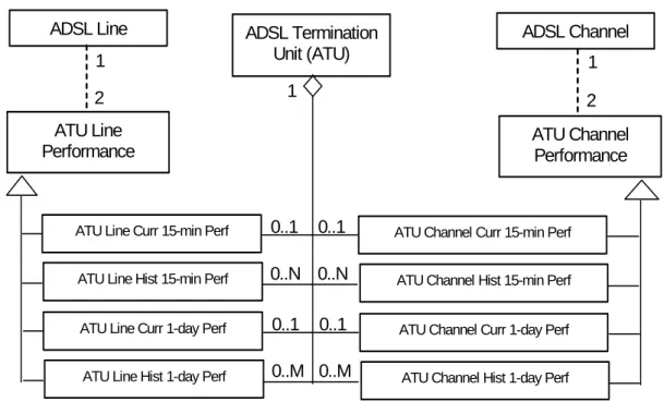
5.3 Object model for ADSL Performance Management
Figure-7 shows the object model relating to ADSL Line performance management. ATU Line Performance ADSL Termination Unit (ATU) 1 ATU Channel Performance
ATU Line Curr 15-min Perf ATU Line Hist 15-min Perf
ATU Channel Curr 15-min Perf ATU Channel Hist 15-min Perf
0..1 0..N
0..1 0..N
ADSL Line ADSL Channel
1 1
2 2
ATU Line Curr 1-day Perf ATU Line Hist 1-day Perf
ATU Channel Curr 1-day Perf ATU Channel Hist 1-day Perf
0..1 0..M
0..1 0..M
N : Maximum number of 15-min intervals supported M : Maximum number of 1-day intervals supported
Figure 7: Managed Object Model – ADSL Performance Management
5.3.1 ATU Line Performance
The ATU Line Performance object represents line performance related data for a given ATU. It is only a super-class that cannot be instantiated. It supports following sub-classes that are instantiated:
¾ ATU Line Current 15-min Performance
¾ ATU Line History 15-min Performance
¾ ATU Line Current 1-day Performance
¾ ATU Line History 1-day Performance
Following attributes are supported for ATU Line Performance object:
¾ Interval Number (0 for current; 1..N/M for previous/history intervals)
¾ Interval Status (valid – Data is valid and complete; invalid – Data is invalid or incomplete)
¾ Errored Seconds – Line (ES-L/LFE)
¾ Severely Errored Seconds – Line (SES-L/LFE)
¾ Loss of Signal Seconds – Line (LOSS-L/LFE)
¾ Unavailable Seconds – Line (UAS-L/LFE)
¾ Full Initializations **
¾ Failed Full Initializations **
¾ Short Initializations **
¾ Failed Short Initializations ** NOTE:
Object instances associated with the ATU-C use the xxx-L version of the parameter while those associated with the ATU-R use xxx-LFE version of the parameter.
**: These parameters apply only to instances of the object associated with the ATU-C.
Instances of this object are supported for each ATU (ATU-C or ATU-R) for the current and previous N 15-minute intervals, as well as for current and previous M 1-day intervals.
5.3.2 ATU Channel Performance
The ATU Channel Performance object represents channel performance related data for a particular channel associated with a particular ATU. It is only a super-class that cannot be instantiated. It supports following sub-super-classes that are instantiated:
¾ ATU Channel Current 15-min Performance
¾ ATU Channel History 15-min Performance
¾ ATU Channel Current 1-day Performance
¾ ATU Channel History 1-day Performance
Following attributes are supported for ADSL Channel Performance object:
¾ Interval Number (0 for current; 1..N/M for previous/history intervals)
¾ Interval Status (valid – Data is valid and complete; invalid – Data is invalid or incomplete)
¾ Code Violations – Channel (CV-C/CFE)
¾ Forward Error Corrections – Channel (FEC-C/CFE) NOTE:
Object instances associated with the ATU-C use the xxx-C version of the parameter while those associated with the ATU-R use xxx-CFE version of the parameter.
Instances of this object are supported for each channel associated with each ATU (ATU-C or ATU-R) for the current and previous N 15-minute intervals, as well as for current and previous M 1-day intervals.
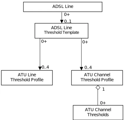
5.4 Object model for ADSL Performance Threshold Management
Figure-8 shows the object model relating to ADSL Line performance threshold management. ADSL Line ATU Channel Thresholds 1 0+ ADSL Line Threshold Template 0+ 0..1 ATU Line Threshold Profile ATU Channel Threshold Profile 0..4 0..4 0+ 0+
Figure 8: Managed Object Model – ADSL Performance Threshold Management
5.4.1 ADSL Line Threshold Template
The ADSL Line Threshold Template object represents a complete set of performance monitoring thresholds for an ADSL Line.
Following attributes are supported by the ADSL Line Threshold Template object:
¾ Template Name
¾ Pointer to the ATU-C 15-min Line Threshold Profile
¾ Pointer to the ATU-C 1-day Line Threshold Profile
¾ Pointer to the ATU-R 15-min Line Threshold Profile
¾ Pointer to the ATU-R 1-day Line Threshold Profile
¾ Pointer to the ATU-C 15-min Channel Threshold Profile
¾ Pointer to the ATU-C 1-day Channel Threshold Profile
¾ Pointer to the ATU-R 15-min Channel Threshold Profile
5.4.2 ATU Line Threshold Profile
The ATU Line Threshold Profile object represents a set of performance monitoring thresholds for an ADSL Line at a particular ATU.
Following attributes are supported by the ATU Line Threshold Profile object:
¾ Profile Name
¾ Forward Error Correction Seconds - Line Threshold (FECS-L/LFE)
¾ Errored Seconds – Line Threshold (ES-L/LFE)
¾ Severely Errored Seconds – Line Threshold (SES-L/LFE)
¾ Loss of Signal Seconds – Line Threshold (LOSS-L/LFE)
¾ Unavailable Seconds – Line Threshold (UAS-L/LFE)
¾ Full Initializations Threshold **
¾ Failed Full Initializations Threshold **
¾ Short Initializations Threshold **
¾ Failed Short Initializations Threshold ** NOTE:
Object instances associated with the ATU-C use the xxx-L version of the threshold while those associated with the ATU-R use xxx-LFE version of the threshold.
**: These thresholds apply only to instances of the object associated with the ATU-C.
5.4.3 ATU Channel Threshold Profile
The ATU Channel Threshold Profile object is a logical-container of performance monitoring thresholds for all channels associated with an ADSL Line at a
particular ATU.
Following attributes are supported by the ATU Channel Threshold Profile object:
¾ Profile Name
5.4.4 ATU Channel Thresholds
The ATU Channel Thresholds object represents a set of performance monitoring thresholds for a particular channel associated with an ADSL Line at a particular ATU.
Following attributes are supported by the ATU Channel Thresholds object:
¾ Channel Number
¾ Code Violations – Channel Threshold (CV-C/CFE)
¾ Forward Error Corrections – Channel Threshold (FEC-C/CFE) NOTE:
Object instances associated with the ATU-C use the xxx-C version of the threshold while those associated with the ATU-R use xxx-CFE version of the threshold.
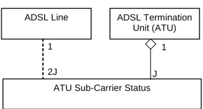
5.5 Object model for ADSL Testing / Diagnostics
Figure-9 below shows the object model relating to detailed ADSL Line testing / diagnostics.
ATU Sub-Carrier Status
ADSL Termination Unit (ATU) J 1 ADSL Line 2J 1
J : Maximum number of Sub-Carriers supported
Figure 9: Managed Object Model – ADSL Testing / Diagnostics
5.5.1 ATU Sub-Carrier Status
The ATU Sub-Carrier Status object represents current detailed status /
measurements relating to a particular sub-carrier in an ADSL Line at a particular ATU.
Following attributes are supported for ATU Sub-Carrier Status object:
¾ Sub-Carrier Number (1..J)
¾ Channel Characteristics Function Linear Representation Scale (HLINSCds / HLINSCus)
¾ Channel Characteristics Function Linear Representation (HLINpsds / HLINpsus)
¾ Channel Characteristics Function Logarithmic Measurement Time (HLOGMTds / HLOGMTus)
¾ Channel Characteristics Function Logarithmic Representation (HLOGpsds / HLOGpsus)
¾ Quiet Line Noise PSD Measurement Time (QLNMTds / QLNMTus)
¾ Quiet Line Noise PSD (QLNpsds / QLNpsus)
¾ Signal-to-Noise Ratio Measurement Time (SNRMTds / SNRMTus)
¾ Signal-to-Noise Ratio (SNRpsds / SNRpsus)
¾ Bits Allocation (BITSpsds / BITSpsus)
¾ Gains Allocation (GAINSpsds / GAINSpsus)
¾ Transmit Spectrum Shaping (TSSpsds / TSSpsus) NOTE:
Object instances associated with the ATU-C use the xxxds version of the parameter while those associated with the ATU-R use xxxus version of the parameter.
References
[1] ITU-T Recommendation G.992.1 (1999), Asymmetric Digital Subscriber Line (ADSL) transceivers.
[2] ITU-T Recommendation G.992.2 (1999), Splitterless Asymmetric Digital Subscriber Line (ADSL) transceivers.
[3] ITU-T Recommendation G.992.3 (2002), Asymmetric Digital Subscriber Line (ADSL) transceivers -2 (ADSL2)
[4] ITU-T Recommendation G.992.4 (2002), Splitterless Asymmetric Digital Subscriber Line (ADSL) transceivers - 2 (ADSL2)
[5] ITU-T Recommendation G.992.5 (2003), Asymmetric Digital Subscriber Line (ADSL) transceivers– Extended Bandwidth ADSL2 (ADSL2plus)
[6] ITU-T Recommendation G.997.1 (2003), Physical layer management for Digital Subscriber Line (DSL) Transceivers (G.ploam_bis)
[6a] ITU-T Recommendation G.997.1 Ammendment-1 (December 12, 2003),
Physical layer management for Digital Subscriber Line (DSL) Transceivers (G.ploam_bis)
[7] DSL Forum Technical Report TR-005 (1998), ADSL Network Element Management.
[8] DSL Forum Technical Report TR-027 (1999), SNMP-based ADSL Line MIB. [9] DSL Forum Technical Report TR-028 (1999), CMIP Specification for ADSL
Network Element Management.
[10] IETF RFC 2662 (1999), Definitions of Managed Objects for the ADSL Lines. [11] IETF RFC 3440 (2002), Definitions of Extension Managed Objects for
Asymmetric Digital Subscriber Lines.
[12] DSL Forum Contribution dslforum2002.178 , "Management of Next Generation ADSL Technologies", R. Abbi & F. Devolder, Alcatel.
[13] DSL Forum Technical Report TR-066 (Mar 2004), ADSL Network Element Management (update to TR-005).