Faculty of Engineering
Menoufia University
DOI: 10.21608/erjm.2021.40296.1036
SFC Optimization of Gas Turbine Cycle Using Air Pre-Cooling Unit:
Performance Improvement
Elsayed A. El-Agouz, Mohamed Abdelgaied, Atef G.A. Ellaamy
*Mechanical Power Engineering Department, Faculty of Engineering, Tanta University, Egypt.
*
(Corresponding author: [email protected])
ABSTRACT
A critical issue concerning the gas turbine cycle of combined cycle power station is the reduction in net power output considerably with increasing ambient air temperature. The present simulation study aims to improve the performance of gas turbine cycle of combined cycle power station through use the fresh air handling units of mechanical chiller. To obtains the influence of use the mechanical chiller as pre-cooling units on a performance of gas turbine cycle, the thermodynamic analysis are used to simulate the performance of gas turbine cycle for three different operating loads (66.67, 83.33, and 100% full load). Based on results of the simulation analysis, the mechanical chiller which is inserted as a pre-cooling unit can; (i) increase the average monthly net power output by values varying between 7.33-18.17 MW compared to the original case without pre-cooling units; (ii) the rate of improvement in the average monthly net power output varies between 4.6-11% compared to the case without pre-cooling units; (iii) reduce the specific fuel consumption (SFC) by a rate varying between 5.21-10.81 kgfuel/MWh compared to the original case without
cooling units; and (iv) the saving in SFC reached to 4.4% compared to the original case without pre-cooling units.
Keywords: Combined cycle, Gas turbine cycle, Mechanical chiller, Performance improvement, SFC optimization.
1. Introduction
As a result of increasing the demand for electricity, whether for domestic or industrial use, research is being carried out continuously on higher-efficiency combined power plant that utilizes natural gas fuel [1-5]. And since the gas turbine represents a main component of the combined power stations, this requires continuous development to enhance their performance. Whereas, the recent developments on gas turbines have lead to an improvement of their efficiency in excess over 40%, as well as for combined cycle when using fuel with low heating value, which leads to an increase in efficiency over 60% [6-11].
The gas turbines have some defects during operation. The most important of these disadvantages is that they produce less net power output during hot ambient because their performance largely depends on a temperature of ambient air surrounding the gas turbine units. In order to increase the net power output during the hot weather, it's necessary to reduce a temperature of the air flowing to gas turbines. Use the air pre-cooling technologies are the most cost effective for improving the gas turbine performance
[12-15]. The air pre-cooling technologies used in gas turbine may be absorption chillier, mechanical chillier, evaporative cooler, inlet fogging, etc. The evaporative cooler consists from air blower and water distribution system connected to water pump. The evaporative cooler is characterized by very low capital cost, but is defective in low cooling effect as compared to other cooling technologies [16]. The mechanical chillier is characterized by having a coefficient of performance higher than 6 [17]. Therefore, it has a higher cooling effect, but it has the drawback that it needs higher electrical energy to drive it. Likewise, for absorption chillier, it is characterized by the fact that it does not consume electricity, except for operation of pumps that need low electrical power, which can be neglected. In addition, the absorption chillier characterized by higher coefficient of performance such as absorption chillers with double-effect those have coefficient of performance reach to about 1.5 [18]. Absorption chillier integrated with combined cycle power plants to cool the inlet air was conducted by [18].
Ameri and Hejazi [19] examined the influences of absorption chiller use to cool the inlet air on a
Turbine Cycle Using Air Pre-Cooling Unit: Performance Improvement"
behavior of 16.60 MW Chabahar gas turbine plant. They found that the use of absorption chiller improves the net power by 11.3%. Also, the economical studied presented that a payback time is 4.2 years. Kakaras et al. [20] used a model to study the influences of absorption chiller on a reduction in the inlet air temperature of gas turbine. Mohammad and Mohamed [21] used the desiccant cooling technology to cool the air inlet to gas turbine system. Some studies were conducted to calculate the coolant flow rate [22-24]. Farzaneh-Gord and Deymi-Dashtebayaz [25] compared between three different cooling techniques (turbo-expanders, mechanical chiller, and evaporative media system) used to cool the air inlet to gas turbines. Moon et al. [26] examined the influence of the turbine inlet temperature on a performance of gas turbines. Kwon et al. [27] used the absorption chiller to pre-cool air inlet to gas turbine of combined cycle. They found that use the absorption chiller to pre-cool inlet air to gas turbine improve a net power by 8.2%. Mohapatra and Sanjay [28] used two cooling technologies (vapor compression cooling system and evaporative cooler) to pre-cool the air inlet to gas turbine. They conducted that the improvement in plant specific work reached to 18.4% and 10.48% for using vapor compression cooling system and evaporative cooling system, respectively.
The present simulation study aims to enhance a performance of gas turbine cycle of Talkha combined cycle power station. To inveterate this idea, we proposed a mechanical chiller installed on the air path inlet to the compressor to pre-cool the air before entering to gas turbine system. The pre-cooling unit utilized to cool the air consists of fresh air handling units connected to mechanical chiller. The thermodynamic analysis of gas turbine cycle of Talkha combined power station integrated with mechanical chiller to pre-cooling the air inlet to gas turbine cycles was investigated. Also, in this study the effect of mechanical chiller as a pre-cooling unit on a degree of coolant cooling, rate of air mass flow inlet to compressor, net power, specific fuel consumption, and thermal efficiency was investigated.
2. System descriptions
The present study aims to enhance the performance of the gas turbine cycle. For a gas turbine operating cycle, a net output power is the difference between turbine power and compressor power. Therefore, the net output power of the gas turbine system depends to a large extent on the compressor input power. Therefore, the power consumed by the compressor is
proportional directly with air inlet temperature. This means that, if a compressor inlet temperature is decreased and density of air inlet to compressor is increased, it will, in turn, affect the gas turbine cycle performance. The data in this study was obtained from the operational located at Talkha Combined Cycle power station. The parameters utilized for this work was generated from a log sheet during the period of January to December 2018. Fig. 1 shows the Talkha Combined cycle power station used in this study. In this study, the proposed cooling system (mechanical vapor compression chiller) was applied to cool the air inlet to the compressor of the turbine cycle as shown in Fig. 1.
Figure 1- Layout diagram of Talkha Combined cycle power station
The simulation study was conducted with a pre-cooler installed on air path inlet to the compressor to pre-cool the air. The pre-cooler utilized to cool the air consists of air handling units connected to a mechanical chiller. The number of fresh air handling units used in this study was calculated based on the size of fresh air handling unit and compressor air flow rate at full load. Fig. 2 shows air handling unit that used in the present simulation study. Specifications of the gas turbine cycle and the fresh air handling unit used in this simulation study are presented in Table. 1. The fresh air handling unit is usually a large metal box containing the blower; filter racks, cooling coils; dampers, and sound attenuators.
Table 1- Specifications of gas turbine cycle of Talkha combined power station and the fresh air handling unit
Gas turbine cycle of Talkha Combined power station
Components Parameters Units Values From Log sheet
Compressor
Inlet Temperature, To3
Outlet Temperature, To4
Inlet Pressure, Po3
Outlet Pressure, Po4
Air Mass flow rate, ̇ Air volume flow rate Isentropic Efficiency K K bar bar kg/s m3/s % Variable Values Variable Values 0.9998 17.3 667.3 577.62 85 Combustion Chamber Inlet Temperature, To4 Max.Temperature,To5 Inlet Pressure, Po4 Outlet Pressure, Po5
Mass flow rate of fuel, ̇
K K bar bar kg/s Variable Values 1600 17.3 17.3 13.9 Turbine Inlet Temperature, To5 Outlet Temperature, To6 Inlet Pressure, Po5 Outlet Pressure, Po6
Mass flow rate, ̇ Isentropic Efficiency K K bar bar kg/s % 1503 852.8 17.3 1.013 681.2 87 Exhaust Gases temperature, To6
Gases pressure,Po6
Mass flow rate, ̇
K bar kg/s 852.8 1.013 681.2
Fresh air handling unit of mechanical chiller
Evaporator Blower Nominal air flow rate Minimum air flow rate Maximum air flow rate Motor power CFM (L/S) CFM (L/S) S/L MsC sk 01111 ( 9<70 =111 ( 8<<;t= 07111 ( :;;:t7 <t: Evaporator Coil Tube dia.
Number of rows Face area,
Total cooling capacity for each unit
Sensible cooling capacity for each unit Inch - Sq. ft. (Sq. m.) kW kW 3/8 6 28.7(2.66) 98.67 74.16
t..ujjm .ju. Compressor power for each unit sk 7:t;9
rebmuN fo oNurf riN fraldiah eaiu
rfbsNurrfN riN odff Nruu ru 011% oedd dfrl riN odff Nruu ofN uraf oNurf riN fraldiah eaiu 755 26 b
3
r 1 7227 6 01 3 b3r 1
010 979 016 eaiur
In the present simulation study, two options have been taken in designing the present configurations. In
the first option, the gas turbine cycle of Talkha combined cycle power station working without
pre-Turbine Cycle Using Air Pre-Cooling Unit: Performance Improvement"
cooling units. In the second option, we installed the 102 fresh air handling units on the air path inlet to the compressor to pre-cool air before inlet to compressor of gas cycle of Talkha combined cycle power station. For two options the gas turbine cycle operated under three different operating capacities (in the first operating case the plant operated at 66.67% full load, in the second operating case the plant operated at 83.33% full load, and in the third operating case the plant operated at 100% full load). All fresh air handling units were connected in parallel. The outlet cold air from the fresh air handling unit represents the supply inlet air to the compressor.
3. Calculation procedure 3.1. For pre-cooling units
Procedure of calculating the temperature of air inlet to compressor
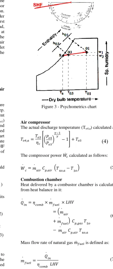
The procedure used to calculate the inlet temperature of cooled air to the compressor includes two-step. The first step by given the ambient air data (ambient air temperature To1 and relative humidity RHo1)
recorded in the operational log sheet within a period of January-December 2018 in Talkha combined Cycle power station. From a psychometrics chart shown, in Fig. 3 by given To1 and RHo1 we calculate
ho1. In the second step by given TC, SC, and SHF
given in equations (1:3) we obtain the temperature of cold air inlet to the compressor To3.
Total cooling capacity, TC of pre-cooling units could be calculated as follows:
𝐶𝑇 ̇ (ℎ11 ℎ13) 0(
Sensible cooling capacity, SC of pre-cooling units calculated as follows:
𝐶𝑇 ̇ 𝑇𝑝 (𝐶11 𝐶13) 7(
The sensible heat factor, SHF calculated as follows:
𝐶𝐻𝑆 𝐶𝑆𝑏𝑖𝑠𝑛𝑒𝑆 𝑇𝑖𝑖𝑒𝑠𝑏𝐶 𝑇𝑐𝑖𝑐𝑎𝑠𝑎𝐶 𝐶𝑇
𝐶𝑖𝑎𝑐𝑒 𝑇𝑖𝑖𝑒𝑠𝑏𝐶 𝑇𝑐𝑖𝑐𝑎𝑠𝑎𝐶 𝐶𝑇 8( 2.3
. elr c e ibrut F r roF
After obtaining the temperature of cold air inlet to compressor in the above section and by given the specifications of the gas cycle of Talkha combined power station presented in Table 1 and the equations (4-12) we calculated the net power and thermal
efficiency as presented as follows:
Figure 3 - Psychometrics chart
Air compressor
The actual discharge temperature (To4,a) calculated as: 𝐶1 𝐶13*( 1
13
)
1
0+ 𝐶13
9
(
The compressor power ̇ calculated as follows:̇ ̇
𝑇𝑝 (𝐶 1 𝐶31) :(
Combustion chamber
Heat delivered by a combustor chamber is calculated from heat balance in it:
𝑄̇ 𝑖 1𝑜𝑐 ̇ 𝑉𝐻𝐿 ( ̇ ̇ ) 𝑇𝑝 𝐶51 ̇ 𝑇𝑝 𝐶 1 ( ;
Mass flow rate of natural gas ̇ is defined as:
̇ 𝑄̇ 𝑖 1𝑜𝑐 𝑉𝐻𝐿 ( <
Turbine
The actual discharge temperature of gas leaving a turbine (T06,a) can be written as:
𝐶1 𝐶15 { 𝐶15 [ 0 ( 0 ( 15 1 ⁄ ) ) 1 ]} ( =
The power produced from the turbine ̇ calculated as follows:
̇ ̇
𝑇𝑝 (𝐶51 𝐶 1 ) >(
Where;
̇ ̇ ̇
Net power produced from gas turbine cycle ̇ calculated as follows:
̇ ̇ ̇ ̇ ℎ ̇𝑠𝑛𝑎 𝑖 01( Specific fuel consumption SFC is calculated as:
𝑇 211 ḃ ̇
( 00 The plant efficiency of the gas turbine system is calculated as:
𝑝 𝑖
̇𝑖
̇ 𝑉𝐻𝐿
07(
Percentage improvement in net power of gas cycle calculated as follows:
uNauaurhu ibsNf ubuau ia auu sffuN feuseu % [
( ̇𝑖 ) ℎ 11 𝑖 ( ̇𝑖 ) ℎ1 11 𝑖
( ̇𝑖 ) ℎ𝑝 11 𝑖
] 011
Percentage improvement in the plant efficiency of the gas turbine system calculated as follows:
uNauaurhu ibsNf ubuau ia sdrau uooiaiuaa % [
( 𝑝 𝑖 ) ℎ 11 𝑖 ( 𝑝 𝑖 ) ℎ1 11 𝑖
( 𝑝 𝑖 ) ℎ𝑝 11 𝑖
] 011
4. Results and discussions
Fig. 4 shows the average monthly compressor air inlet temperature of gas cycle with/without pre-cooling units for operating capacity equal to 66.67%, 83.33%, and 100% full load. For the operating capacity equal to 66.67% full load as shown in Fig. 4a, average monthly compressor inlet air temperature
of gas turbine cycle varying between 292-305 K and 283-295 K for the case without and with cooling units respectively. The degree of coolant cooling of air inlet to compressor for using the pre-cooling units various between 6-12 K at operating capacity 66.67% full load. For increasing the operating capacity to 83.33% full load, the average monthly compressor inlet air temperature of gas cycle varying between 292-305 K and 283-294 K for the case without and with cooling units respectively as shown in Fig. 4b. Degree of coolant cooling of air inlet to compressor for using the pre-cooling units various between 6-11 K at operating capacity 83.33% full load. Also, with continues increases the operating capacity to 100 % full load as shown in Fig. 4c, the average monthly compressor inlet air temperature of gas turbine cycle varying between 292-305 K and 284-295 K for the case without and with cooling units respectively as shown in Fig. 4b. The degree of coolant cooling of air inlet to compressor for using the pre-cooling units various between 6-10 K at operating capacity 100% full load. As shown in Fig. 4, the results indicated that, the degree of coolant cooling reached to 12 K for using the pre-cooling units. This reduction in the compressor inlet temperature will increase the rate of air mass flow inlet to the compressor at the same volume flow rate. This will be increases a net power output and thermal efficiency, also, decrease specific full consumptions.
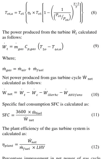
Figs. 5 shows the variations of average monthly compressor inlet air mass flow rate at operating capacity equal to 66.67%, 83.33%, and 100% full load. Fig. 5a shows the average monthly compressor inlet air mass flow rate varying between 426.27-455.61 kg/s and 451.84-473.85 kg/s for gas cycle without/with pre-cooling units respectively at operating capacity equal to 66.67% full loads. The improvement in air mass flow rate inlet to compressor varies between 2.75-6.83% for using gas cycle with pre-cooling units. With increasing the operating capacity to 83.33% full loads as shown in Fig. 5b, the average monthly compressor inlet air mass flow rate varying between 537.97-569.52 kg/s and 564.52-592.13 kg/s for gas cycle without/with pre-cooling units respectively. The improvement in the air mass flow rate inlet to compressor various between 2.75-6.25% for using gas cycle with pre-cooling units at the operating capacity to 83.33% full loads. But with increases the operating capacity to 100% full loads as shown in Fig. 5c, the average monthly compressor inlet air mass flow rate was varying between 645.56-683.42 kg/s and 671.07-709.29 kg/s for gas cycle without/with pre-cooling units respectively. The improvement in the air mass flow rate inlet to compressor various between 2.75-5.74% for using gas cycle with pre-cooling units at
Turbine Cycle Using Air Pre-Cooling Unit: Performance Improvement"
the operating capacity to 100% full loads. This result presented that the improvement in air mass flow rate inlet to compressor for using the gas turbine cycle with pre-cooling units reached to 6.25%.
Figure 4 - Average monthly compressor inlet air temperature at operating load; (a) 66.67%, (b)
83.33%, and (c) 100% of full load
Figure 5 -Variation of average monthly compressor inlet air mass flow rate at operating load; (a) 66.67%,
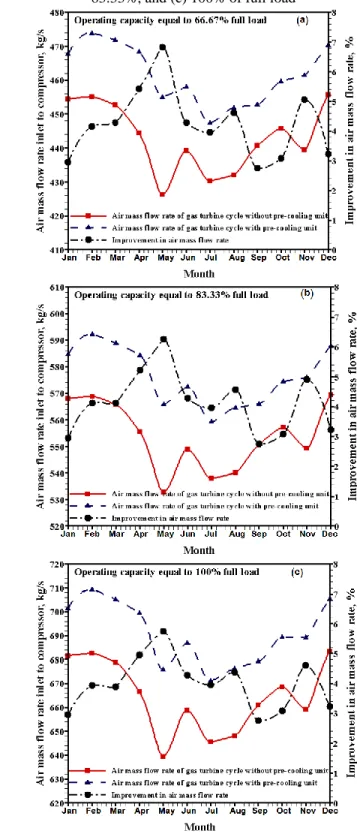
The average monthly net power from the gas cycle at operating capacity equal to 66.67%, 83.33%, and 100% full loads are shown in Figs. 6. As shown in Fig. 6a, average monthly net power output varying between 131.4 -148.72 MW and 142.2-158.9 MW for the gas turbine cycle without/with pre-cooling units respectively at operating capacity equal to 66.67% full loads. At this operating case the improvement in net power output various between 4.6-11% for using the gas turbine cycle with pre-cooling units. With increase the operating capacity to 83.33% full loads as shown in Fig. 6b, the average monthly net power output varying between 164.25-185.9 MW and 177.8-198.5 MW for the gas turbine cycle without/with pre-cooling units respectively. At this operating case the improvement in net power output various between 4.6-10% for using the gas turbine cycle with pre-cooling units. But for increase the operating capacity to 100% full loads as shown in Fig. 6c, the average monthly net power output varying between 197.1-223.1 MW and 213.3-237.4 MW for the gas turbine cycle without/with pre-cooling units respectively. At this operating case the improvement in net power output various between 4.6-9.2% for using the gas turbine cycle with pre-cooling units. The results of average monthly net power presented that the improvement in net power reached to 13.19% for using the gas turbine cycle with pre-cooling units as compared to case without pre-cooling units.
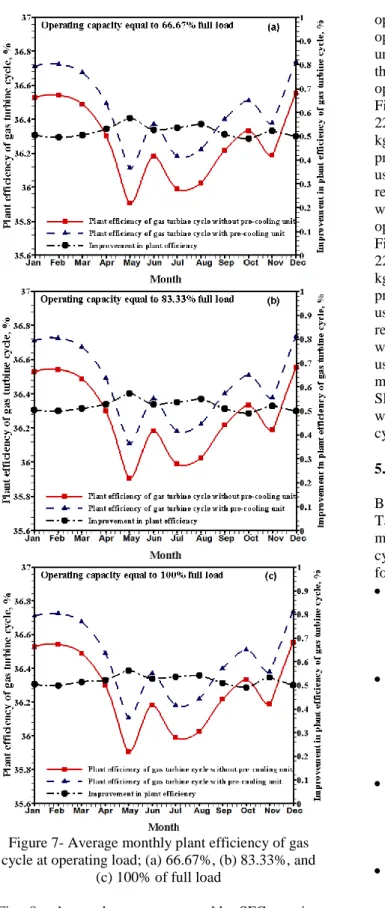
The average monthly plant efficiency of gas cycle at operating capacity 66.67%, 83.33%, and 100% full loads are presented in Figs. 7. Fig. 7a shows the average monthly plant efficiency varying between 35.9-36.55% and 36.1-36.74% for the gas turbine cycle operated without/with pre-cooling units respectively at operating capacity 66.67% full loads. At this operating case the improvement in plant efficiency various between 0.5-0.55 % for using the gas turbine cycle with pre-cooling units. With increase the operating capacity to 83.33% full loads as shown in Fig. 7b, the average monthly plant efficiency varying between 35.9-36.55% and 36.11-36.74% for the gas turbine cycle without/with pre-cooling units respectively. At this operating case the improvement in plant efficiency various between 0.49-0.57% for using the gas turbine cycle with pre-cooling units. But for increase the operating capacity to 100% full loads as shown in Fig. 7c, the average monthly plant efficiency varying between 35.9-36.55% and 36.1-36.74% for the gas turbine cycle without/with pre-cooling units respectively. At this operating case the improvement in plant efficiency various between 0.49-0.56% for using gas cycle with pre-cooling units.
Figure 6- Average monthly net power output from the gas turbine cycle at operating load; (a) 66.67%,
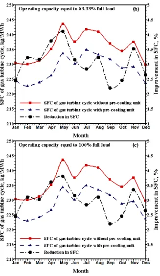
(b) 83.33%, and (c) 100% of full load The average monthly specific fuel consumption SFC of gas cycle at operating capacity 66.67%, 83.33%, and 100% full loads are presented in Figs. 8.
Turbine Cycle Using Air Pre-Cooling Unit: Performance Improvement"
Figure 7- Average monthly plant efficiency of gas cycle at operating load; (a) 66.67%, (b) 83.33%, and
(c) 100% of full load
Fig. 8a shows the average monthly SFC varying between 230-243.59 kgfuel/MWh and 222.59-234.88
kgfuel/MWh for the gas turbine cycle operated
without/with pre-cooling units respectively at
operating capacity 66.67% full loads. At this operating case, the gas turbine cycle with pre-cooling units reduces the SFC by 2.2-4.4% as compared with the case without pre-cooling units. With increase the operating capacity to 83.33% full loads as shown in Fig. 8b, the average monthly SFC varying between 229.75-243.59 kgfuel/MWh and 222.63-234.88
kgfuel/MWh for the gas turbine cycle without/with
pre-cooling units respectively. At this operating case, use the gas turbine cycle with pre-cooling units reduces the SFC by 2.2-4.1% as compared to the case without pre-cooling units. But for increase the operating capacity to 100% full loads as shown in Fig. 8c, the average monthly SFC varying between 229.75-243.59 kgfuel/MWh and 222.91-234.33
kgfuel/MWh for the gas turbine cycle without/with
pre-cooling units respectively. At this operating case, use the gas turbine cycle with pre-cooling units reduces the SFC by 2.2-3.8% as compared to the case without pre-cooling units. The results presented that, using the gas turbine cycle with pre-cooling units are more effective which the percentage reduction in the SFC reached to 5.51% for using gas turbine cycle with pre-cooling units as compared to the gas turbine cycle without pre-cooling units.
5. Conclusions
Based on the thermodynamic analysis of gas cycle of Talkha combined power station integrated with mechanical chiller to pre-cooling the air inlet to gas cycles, the main conclusions are summarized as follows:
The improvement in the rate of air mass flow inlet to compressor for using the mechanical chiller as a pre-cooling unit reached to 6.83, 6.25, and 5.74% at operating capacity equal to 66.67%, 83.33%, and 100% full load, respectively. The increases in average monthly net power
output for using the mechanical chiller as a pre-cooling units varying between 7.33-14.47, 8-16.5, and 9.63-18.17 MW at operating capacity equal to 66.67%, 83.33%, and 100% full load, respectively.
The improvement in average monthly net power output for using the mechanical chiller as a pre-cooling unit reached to 11, 10, and 9.2% at operating capacity equal to 66.67%, 83.33%, and 100% full load, respectively.
Improvement in plant efficiency of gas turbine cycles various between 0.49-0.55 % for using the gas turbine cycle with pre-cooling units.
The saving in specific fuel consumption in gas turbine cycle for using the mechanical chiller as a pre-cooling units varying between 5.21-10.81,
5.21-9.99, and 5.21-9.26 kgfuel /MWh at operating
capacity equal to 66.67%, 83.33%, and 100% full load, respectively.
The improvement in specific fuel consumption for using the mechanical chiller as a pre-cooling unit reached to 4.4, 4.1, and 3.8% at operating capacity equal to 66.67%, 83.33%, and 100% full load, respectively.
eluF ro ibrF s uuloe
S
b Heat capacity at constant pressure, kJ/kg K
g Cbtyu uy tj.grebci scssh MHL Lower heating value, kJ/kg
̇ Mass flow rate, kg/s P Pmt//.mti prm
CS Ctj/upet yjjeujh yrbryu.ci sk
C/S Specific fuel consumption, kgfuel /MWh
T Ttrbtmr..mti T
TS Tj.re yjjeujh yrbryu.ci sk
̇ Pj tmi sk lrFFy s uulo η % ,y uyutjyc γ Cbtyu uy gtr. mr.uj s nuurFit itl CH/ Ctj/upet gtr. ry.jm UHA Uum grjueujh .ju.
sbuerrtui
r ry..re
y yjrbmt//jm
uj ujet.
. .mpujt T
Figure 8- Average monthly SFC of the gas cycle at operating load; (a) 66.67%, (b) 83.33%, and (c)
100% of full load
6. References
[1] Carcasci C., Cosi L, Ferraro R., Pacifici B., “Effect of a real steam turbine on thermo-economic analysis of combined cycle power plants”. Energy 138 (2017) 32-47.
[2] Kotowicz J., Job M., Brze˛czek M., “The characteristics of ultramodern combined cycle power plants”. Energy 92 (2015) 197-211. [3] Best T., Karen N. Finney, Derek B. Ingham,
Mohamed Pourkashanian, “CO2-enhanced and
humidified operation of a micro-gas turbine for carbon capture”. Journal of Cleaner Production 176 (2018) 370-381.
[4] Torres-Carrillo S., Hector R. Siller, Carlos Vila, Cecilio Lopez, Ciro A. Rodríguez, “Environmental analysis of selective laser melting in the manufacturing of aeronautical turbine blades”, Journal of Cleaner Production 246 (2020) 119068.
Turbine Cycle Using Air Pre-Cooling Unit: Performance Improvement"
[5] Mikhail Granovskii, Ibrahim Dincer, Marc A. Rosen, “Performance comparison of two combined SOFC–gas turbine systems”, Journal of Power Sources 165 (2007) 307–314.
[6] Hada S., Takata K., Iwasaki Y., Yuri M., Masada J. “High-efficiency gas turbine develop-ment applying 1600o class J technology” Mitsubishi Heavy Industries Technical Review; 2015. p.52.
[7] Fischer W. J., Nag P., “H-Class high performance Siemens gas turbine (SGT-8000H series)”. Las Vegas, Nevada, USA: Power Gen International; 2011.
[8] Roy D., Samiran Samanta, Sudip Ghosh, “Techno-economic and environmental analyses of a biomass based system employing solid oxide fuel cell, externally fired gas turbine and organic Rankine cycle”. Journal of Cleaner Production 225 (2019) 36-57.
[9] Azra Selimovic, Jens Palsson, “Networked solid oxide fuel cell stacks combined with a gas turbine cycle”. Journal of Power Sources 106 (2002) 76-82.
[10] Dustin McLarty, Jack Brouwer, Scott Samuelsen, “Fuel cellegas turbine hybrid system design part I: Steady state Performance”. Journal of Power Sources 257 (2014) 412-420. [11] Piero Lunghi, Roberto Bove, Umberto Desideri,
“Analysis and optimization of hybrid MCFC gas turbines plants”. Journal of Power Sources 118 (2003) 108–117.
[12] Singh OK., “Performance enhancement of combined cycle power plant using inlet air cooling by exhaust heat operated ammonia-water absorption refrigeration system”. Applied Energy 180 (2016) 867-879.
[13] Kyoung Hoon Kim, Hyung-Jong Ko, Kyoungjin Kim, Horacio Perez-Blanco. “Analysis of water droplet evaporation in a gas turbine inlet fogging process”. Appl. Therm. Eng. 33(4) (2012) 62-69.
[14] Mertens J., Anne Prieur-Vernat, Dominique Corbisier, Elsa Favrot, Gustaaf Boon, “Water foot printing of electricity generated by combined cycle gas turbines using different cooling technologies: a practitioner's experience”. Journal of Cleaner Production 86 (2015) 201-208.
[15] Allahyarzadeh-Bidgoli A., Daniel Jonas Dezan, Jurandir Itizo Yanagihara, “COP optimization of propane pre-cooling cycle by optimal Fin design of heat exchangers: Efficiency and sustainability improvement”. Journal of Cleaner Production 271 (2020) 122585.
[16] Farzaneh-Gord M., Mahdi Deymi-Dashtebayaz,
“Effect of various inlet air cooling methods on gas turbine performance”. Energy 36 (2011) 1196-1205.
[17] Sanaye S., Tahani M., “Analysis of gas turbine operating parameters with inlet fogging and wet compression processes”. Appl. Therm. Eng. 30 (2010) 234-244.
[18] Popli S., Rodgers P., Eveloy V., “Gas turbine efficiency enhancement using waste heat powered absorption chillers in the oil and gas industry”. Appl Therm. Eng.50 (2013) 918-931. [19] Ameri M., Hejazi S. H., “The study of capacity
enhancement of the Chabahar gas turbine installation using an absorption chiller”. Applied Thermal Engineering 24 (2004) 59-68 [20] Kakaras E., Doukelis S., Karellas S.,
“Compressor intake-air cooling in gas turbine plants”. Energy 29 (2004) 2347-2358.
[21] Mohammad S., Mohamed G., “Innovative inlet air cooling technology for gas turbine power plants using integrated solid desiccant and Maisotsenko cooler”.Energy 87 (2015) 663-677. [22] Horlock, J. H., Watson D. T., Jones T. V., “Limitations on gas turbine performance imposed by large turbine cooling flows”. J Eng Gas Turbines Power 123 (2001) 487-494. [23] Sciubba E., “Air-cooled gas turbine cycles Part
1: an analytical method for the preliminary assessment of blade cooling flow rates”. Energy 83 (2015) 104-114.
[24] Moskalenko A.B., Kozhevnikov A.I., “Estima-tion of gas turbine blades cooling efficiency”. Procedia Engineering 150 (2016) 61-67. [25] Farzaneh-Gord M, Deymi-Dashtebayaz M.,
“Effect of various inlet air cooling methods on gas turbine performance” Energy 36 (2011) 1196-1205.
[25] Farzaneh-Gord M, Deymi-Dashtebayaz M., “Effect of various inlet air cooling methods on gas turbine performance”. Energy 36 (2011) 1196-1205.
[26] Moon S.W., Hyun Min Kwon, Tong Seop Kim, Do Won Kang, Jeong Lak Sohn, “A novel coolant cooling method for enhancing the performance of the gas turbine combined cycle”, Energy 160 (2018) 625-634.
[27] Kwon M., Tong Kim, Jeong Sohn, Do Kang, “Performance improvement of gas turbine com-bined cycle power plant by dual cooling of the inlet air and turbine coolant using an absorption chiller” Energy 163 (2018) 1050-1061.
[28] Mohapatra A. K., Sanjay, “Comparative analysis of inlet air cooling techniques integrated to cooled gas turbine plant” Journal of the Energy Institute, 88 (2015), 344-358.