2017 3rd International Conference on Electronic Information Technology and Intellectualization (ICEITI 2017) ISBN: 978-1-60595-512-4
GPU Based Rendering of Global
Scale Terrain Data
Baosong Deng, Fangyu Qin and Tieqing Deng
ABSTRACT
Photorealistic terrain rendering has long been an active research topic in computer graphic and 3D GIS. If they are global scale detailed, digital terrains can represent a huge amount of data and therefore of graphical primitives to render in real-time. A dynamic, realistic and fluent rendering scheme for large scale terrain was proposed in this paper, based on LOD tiles,pre-reading strategy and GPU based acceleration. Multi-resolution terrain of global dataset was used for view-dependent data control and grid simplification, and multi-thread mechanism was employed for visibility clipping and data exchange among memory, cache and disk. Experimental results of real data and comparisons with traditional method demonstrate the feasibility, robust and practicality of our method.
INTRODUCTION
Geographic Information System (GIS) applications are now moving towards 3D as it has a better representation of the real world[1]. Interactive visualization of landscapes and outdoor environments is important for various graphics applications, such as 3D GIS, computer games, flight simulators, and virtual exploration of remote planets[2]. Terrain and image datasets are vital components of these virtual environments[3].
The scale and resolution of geospatial datasets continually grow as data capture technologies improve[4]. In this setting, data integration has emerged as one of the ______________________
main challenges in leveraging these huge datasets. In this paper, we present a novel approach for interactive rendering of global scale terrain datasets, which is designed to prevent limitations of previous algorithms, and has nothing to do with the data size. Our approach subdivides the terrain into rectangular patches at different resolutions, and then converts them to spherical coordinate system. By combining carefully designed data structures with the use of GPU based programs[5], multi-thread and view-dependent rendering technologies are used. We evaluate our technique by applying it to dynamic and real data sets.
The Digital Earth framework has been proposed as an infrastructure to address this challenge. Such terrains usually exceed the rendering capability of currently available graphics hardware, and thus reducing their complexity is mandatory for interactivity. Adjusting the complexity of terrain in memory according to view parameters is a common approach for interactive terrain rendering. Pajarola[6] used a restricted quad-tree triangulation for terrain visualization. The main idea shared by the algorithms is to build a regular multi-resolution hierarchy through refinement and simplification.
TILE SYSTEM FOR GLOBAL DATA STRUCTURE
Dealing with huge amounts of global data is a difficult challenge. Simplification algorithms take a terrain model as input and produce a simplified version of it, which provides a coarser representation of the same terrain, based on a smaller data set. Bing Maps, Google Earth, and BaiDu tiles are indexed using quad-tree keys, which is named quadkey. In traditional terrain pyramid model, vertex amount will increase by 4 times when the layer number decreases. So the lower layer blocks cover with more vertexes and larger range of terrain region. Each quadkey number identifies a single tile at a single zoom level. Fig. 1 shows the structure of quad-tree, and Fig. 2 gives an example of image data structure. The patch hierarchy is constructed top-down by subdividing each patch into 2×2 children patches, similar to restricted quad-tree.
Level 2
Level 1
Level 0
Typically, the Mercator projection is used to map image and elevation data to a square area. The Mercator projection is mainly used to minimize distortions in processed images and elevation data. The meridians of the Mercator projection are vertical parallel equally spaced lines, cut at right angles by horizontal straight parallels which are increasingly spaced toward each pole so that conformality is preserved. The maximum latitude is chosen so that the resulting map fits into a square.
Considering rendering efficiency and graphic engine, the size of tiles should be power of 2. Too large size will go beyond the capability of CPU, and too small size will increase the frequency of data exchange. Since the paging size of Intel CPU is 4K Byte, we recommend the terrain width is 32, and the texture width is 256, which improve the storing competence and decrease the remained memory. We adopt vertical skirt mask to eliminate crack. A vertical skirt is created around the perimeter of each terrain block, and the top of the skirt matches the terrain block edge. With this vertical skirt, crack will be filled easily. This method could reduce CPU processing time; though a small number of triangles are added.
DYNAMIC TERRAIN RENDERING
This section describes the process performed at runtime on the GPU in order to generate and visualize the appropriate level of detail. Since the data of terrain always include millions of triangle polygons and large scale of images, which make the models become much finer and complicated. The data is too massive to be loaded in the memory completely. As a result, Out-of-core, view-dependent and multi-thread technologies are used when rendering the virtual world.
Multi-thread Loading and Rendering
Large scale terrain has so many blocks that it cannot be loaded to memory once. So these terrain blocks have to be updated on-the-fly. We design a more reasonable dynamic scheduling scheme, and accomplish efficient management. At least two lists are constructed to store the rendered terrain to realize the management of the read terrain data. One is terrain list mentioned above which will be put into cache to render, the other one is terrain candidate list. The terrain candidate list is a candidate which stores terrain data and textures that could also store the uninstalled or pre-read terrain blocks.
in parallel. Fig. 3 is the data structure of tiles stored and exchanged in the memory, by which we can find parent and children directly.
data structure of tiles
memory storage
Figure 3. Tiles stored in the memory.
The memory to be used for data exchange is tuned by an adaptive parameter, which represents the percentage of available memory that can be used after the non-adaptive part of the environment is fetched. Knowing the amount of memory to be used, the square area is maintained by tracking the viewpoint by fetching/removing tiles to/from memory. In order to perform real-time rendering of massive data and considering current PC configuration, the internal memory only includes the data which need to be rendered. With the efficient algorithm of data schedule, these data can be updated real time. A separate I/O thread dynamically loads the tiles that are located inside the view frustum into main memory. Tiles that have left the pre-fetching region are removed from the tile tree and inserted into tile cache. That makes the best of file system driver development, which enhances the control of file access and the later guarantees the consistent of the data access and file arrangement.
View-dependent Refinement
A significant gain in speed is obtained by culling away geometry that does not need to be rendered. The rendering thread traverses the quad-tree hierarchy in top-down manner and refines the quad-tree hierarchy based on the current viewing parameters. The allowed run-time error is expressed in screen-space as a pixels-of-error (PoE) value, which relates to the overall visual quality directly. For the tile or node that is traversed, we use the PoE value and the minimum distance between the tiles and the viewpoint to compute the maximum object-space error that is allowed for the tile, called the error-bound. If the error-bound is less than the min-error of its error-range, we go on checking its children because the mesh of the current tile cannot meet the error-bound. Otherwise, if the current tile passes the visibility test, we add the tile to an active tiles list and stop traversal.
stop the traversal. Otherwise, we continue checking its children respectively. After this traversal, we can get an active nodes list determined by view dependent error and visibility criteria. Then, we perform fine-grained local refinement for each tile in the active tiles list at the current level, and then send the resulting meshes to the graphics pipeline for rendering.
GPU Based Acceleration
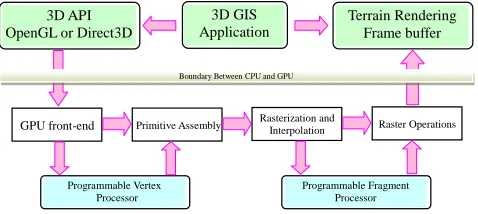
Recent generations of GPU have allowed the design of algorithms that have a substantial part of their workload performed by the GPU. GPU began supporting hardware tessellation with OpenGL 4.0. It is considered more beneficial to allocate coarse-grained control of the terrain data to the CPU, and then, allocate the rest of the processing to the GPU[5]. During runtime, the quad-tree of tiles is partially held and maintained in main memory, dependent on the movements of the viewer. In each update, tiles inside the view frustum are loaded and GPU based pipeline transform them to the frame buffer, as shown in fig.4. The rendering pipeline is mapped onto current graphics acceleration hardware such that the input to GPU is in the form of vertices. These vertices undergo transformation and per-vertex lighting.
GPU front-end Primitive Assembly Rasterization and Interpolation Raster Operations
Programmable Vertex Processor
Programmable Fragment Processor 3D GIS
Application
Terrain Rendering Frame buffer 3D API
OpenGL or Direct3D
[image:5.612.179.418.349.456.2]Boundary Between CPU and GPU
Figure 4. GPU pipeline used in terrain rendering.
The graphics pipeline is well suited to the rendering process because it allows the GPU to function as a stream processor since all vertices and fragments can be thought of as independent. This allows all stages of the pipeline to be used simultaneously for different vertices or fragments as they work their way through the pipe. In addition to pipelining vertices and fragments, their independence allows graphics processors to use parallel processing units to process multiple vertices or fragments in a single stage of the pipeline at the same time. To reduce memory and bandwidth requirements, data compression schemes are employed.
Pre-reading Strategy
choppy. As it will take some time to load the terrain tile into buffer, the terrain needs to be pre-read to facilitate the rendering process.
The pre-reading of tiles uses the multi-thread data loading strategy. The key point is to compare the level of current tile which taken as the key terrain or image with the level of the former frame. If the two values are same, this indicates that the blocks which are being rendering are unnecessary to update. Then the terrain pre-reading could begin. We must take the two factors of terrain tiles level and key terrain number into account when pre-reading. As long as the terrain tiles level or the key terrain number changes, the pre-reading should be carried out.
T C
R
Direction
[image:6.612.195.395.241.324.2](a) First frame and scene center (b) change between tow frames
Figure 5. Pre-reading strategy of terrain tiles.
Fig.5 shows the update clip map. The left is the first frame; the right is change between two frames. The black point is the center of 2D image, T is a top, R is a right, and C is a corner.
RESULTS OF REAL DATASETS
We implemented above idea and method in MS visual studio C++ environment, based on low level graphic API, OpenGL, and the window size is in all cases 1024×768 pixels. We used a 2.66GHz Pentium Dual-Core CPU, with 2GB DDR2 of RAM, NVIDIA GeForce 9300M GS programmable graphic card with 256M RAM, and SATA 1TB disk.
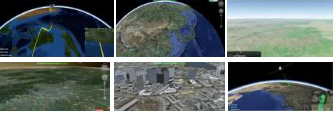
Figure 6. Experimental results of real data sets.
In fig. 6, we can see that our method shows a good capability with large scale terrain, especially for real-time applications. The frame rates are between 50 to 110 fps, the nadir of frame rate is larger than 30 fps even though large data exchange occurs. Results from our analyses suggest that our method largely reduce the triangles number at every frame, and frame rates reached the real-time requirement of our travels. Although storage of the two data sets has biggish contrast, the changes of frame rate are unnoticeable. That is to say, our method is not sensitive to the data scale.
CONCLUSIONS
A global multi-resolution DEM and a feasible solution for its visualization and management remains a challenging vision. In this paper, we have presented a real-time terrain rendering algorithm based on linear quad tree. We re-sample DEM and image for getting the same size blocks, and build terrain pyramid model with different scales and biases factors, which makes the number of rendering vertexes decrease obviously, it could reduce CPU processing time and GPU rendering batches significantly[5]. The improved algorithm, which keeps a high and smooth frame rate, could be used for real-time rendering in large scale terrain.
In the future, we will research on real-time compression of high-resolution photos used as terrain texture, and improve the visual effects of light and shadow. With the implementation of the two parts, we hope our large scale terrain visualization system more realistic while ensuring real-time quality.
REFERENCES
1. Pajarola, R., Gobbetti, E. 2007. “Survey of semi-regular multiresolution models for interactive terrain rendering,” Journal of Visual Computer, 23 (8):583-605.
3. Smelik, R. M. Tutenel, T. Bidarra, R. Benes, B. 2012. “A Survey on Procedural Modeling for Virtual Worlds,” Journal of Computer Graphics Forum, 33(6):31-50.
4. Nie, J. Guo, D. Wang, Y. Kong, L. Tang Y. 2011. “Multilevel Tile Load Map on Massive Terrain Visualization,” Journal of Computational Information System, 7(2):452-461.
5. Amara, Y. Marsault, X. 2009. “A GPU Tile-Load-Map architecture for terrain rendering: theory and applications,” Journal of Visual Computer, 25(8):805-824.
6. Pajarola, R. 1998. “Large scale terrain visualization using the restricted quadtree triangulation,”
In: Proceedings of the conference on Visualization, pp. 19-26. IEEE Computer Society Press, Los