Technology (IJRASET)
THD reduction using Shunt Active Filter
Niranjana Patro1, Upendra Tomar2
Department of Electrical Engineering, Vikrant Institute of Engg & Technology, Gwalior
Abstract: Nowadays, the active filters represent a viable alternative for controlling harmonic levels in industrial consumers’ electrical installations. It must be noted the availability of many different types of filter configurations that can be used but there is no standard method for rating the active filters. This paper is focused on a shunt active filter detection of harmonic voltages at the point of installation. The presence of harmonics in the power lines results in greater power losses in distribution, interference problems in communication systems and, sometimes, in operation failures of electronic equipments.
Index Terms—Harmonic termination, power distribution systems, pulse width modulation inverters, shunt active filters, voltage
detection.
I. INTRODUCTION
NONLINEAR loads such as high-power diode/thyristor rectifiers, cycloconverters, and arc furnaces draw nonsinusoidal currents from utility grids. A single low-power diode rectifier used as a utility interface in an electric appliance produces a negligible amount
of harmonic current. However, multiple low-power diode rectifiers can inject a large amountof current harmonics into power distribution systems. Active filters are an up-to-date solution to power quality problems. Shunt active filters allow the compensation of current harmonics and unbalance, together with power factor correction, and can be a much better solution than the conventional approach (capacitors for power factor correction and passive filters to compensate for current harmonics). This paper presents the p-q theory as a suitable tool to the analysis of non-linear three-phase systems and for the control of active filters. These harmonic-producing loads contribute to the degradation of power quality in transmission/distribution systems.Oku, et al., have reported the serious status of harmonic pollution in Japan [1], [2]. This implies that harmonic damping would be as effective in solving harmonic pollution as harmonic compensation [3]. Hence, electric power utilities have the responsibility for harmonic damping throughout power distribution systems, while individual customers and end users are responsible for harmonic compensation of their own nonlinear loads.
The purpose of a shunt active filter proposed and developed
in this paper is to achieve harmonic damping throughout a
=radial power distribution line subjected to harmonic propagation. The active filter based on voltage detection is intended to be installed by electric power utilities on the distribution line. This paper pays much attention to experimental results which support and follow theoretical analysis and computer simulated results presented in [3] and [14]. Harmonic mitigation of voltage and current is a welcome “byproduct,” which stems from harmonic damping throughout the distribution line. The active filter is controlled in
such a way as to present infinite impedance to the external circuit for the fundamental frequency, and as to exhibit low resistance for harmonic frequencies.
Technology (IJRASET)
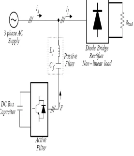
The shunt active filter shown in Fig.1 is the most fundamental system configurations. The shunt APF is controlled to draw and inject compensating current, if to the power system and cancel the harmonic currents on the ac side of a general purpose rectifier. Besides
[image:3.612.161.438.129.451.2]that, it has the capability of damping harmonic resonance between an existing passive filter and the supply impedance.
Figure 2. Hybrid Active Filter
Another type of active filter configuration shown in Fig.2 is the Hybrid Active-Passive Filters (HAPF). The HAPF’s consists of the combination of the active and passive filter in order to perform better. Hybrid active filters inherit the efficiency of passive filters and the improved performance of active filters, and thus constitute a viable improved approach for harmonic compensation. The combination can be in different ways such as the combination of shunt active filter and shunt passive filter, or combination of series active filter and shunt passive filter, or combination of active filter connected in series with shunt passive filter and many more. Each of these combinations will have different performance. However, the combination of shunt active and shunt passive filter is more commercialized and more commonly used. The series active filter with shunt passive filter is usually used in testing Field.
II. SYNCHRONUS D-Q REFRENCE FRAME THEORY
A shunt active filter connected to a simple power system is shown in Fig. 1. Assume that non-linear loads are connected at point of common coupling (PCC). The system comprises balanced three phase voltage source (Va, Vb , Vc) feeding a three phase diode bridge rectifier with resistive load. The SAF is connected to three phase through inductor L. Converter employed for SAF is MOSFET based converter , it is a current controlled voltage source inverter which is connected in parallel with load. This inverter injects the reference compensating current into system to compensate harmonics components of load current. The quality and performance of SAF is depending on technique used to harmonic detection and current controller topologies. DC storage capacitor is used as input of VSI DC link voltage. This DC link voltage is maintain constant by adding external loop in generation of reference compensating current topology. VSI firing pulses are generated by current co The three-phase load currents (iLA, iLB, and
Technology (IJRASET)
positive sequence of the system voltage as given below control topologies.
The corresponding inverse relation is
The current and flux linkages can be transformed by similar equations. It is convenient to set θ = 0, so that the qs – axis is aligned with the as-axis. Ignoring the zero sequence components, the transformation relations can be simplified as
And inversely
III. DESIGN OF PI CONTROLLER
The controller used is the discrete PI controller that takes in the reference voltage and the actual voltage and gives the maximum value of the reference current depending on the error in the reference and the actual values [8]. The mathematical equations for the discrete PI controller are:
The voltage error V (n) is given as:
The output of the PI controller at the nth instant is given as:
When the DC link voltage is sensed and compared with the reference capacitor voltage, to estimate the reference current, the compensated source current will also have sixth harmonic distortion.
IV. SIMULATION RESULT
A MATLAB simulation is done to implement shunt active filter using synchronous d-q theory. A sinusoidal three phase supply is
Technology (IJRASET)
Figure.3 Simulation Circuit Diagram
Figure.4 Source and Load current waveform
Technology (IJRASET)
Fig.6 Converter current and source voltage waveform
Fig.7 THD waveform
V. CONCLUSION
The pulses to the current controlled voltage source inverter which acts as shunt active filter is generated using a synchronous d-q reference frame control technique with hysteresis current control loop. Result shows power factor is improved nearer to unity. Source current THD reduces as per the recommended harmonics standards IEEE 519.
REFERENCES
[1] K. Oku, O. Nakamura, and K. Uemura, “Measurement and analysis of harmonics in power distribution systems, and development of a harmonic suppression method,” Trans. IEEJ, vol. 114-B, no. 3, pp.234–241, 1994.
[2] K. Oku, O. Nakamura, J. Inoue, and M. Kohata, “Suppression effects of active filter on harmonics in a power distribution system including capacitors,” Trans. IEEJ, vol. 115-B, no. 9, pp. 1023–1028, 1995.
[3] H. Akagi, “New trends in active filters for power conditioning,” IEEE Trans. Ind. Applicat., vol. 32, pp. 1313–1322, Nov./Dec. 1996. [4] L. Gyugyi and E. C. Strycula, “Active ac power filters,” in Proc.IEEE-IAS Annu. Meeting, 1976, pp. 529–535.
[5] H. Kawahira, T. Nakamura, S. Nakazawa, and M. Nomura, “Activepower filters,” in Proc. 1983 Int. Power Electronics Conf., Tokyo, Japan, 1983, pp. 981– 992.
[6] H. Akagi, A. Nabae, and S. Atoh, “Control strategy of active power filters using multiple voltage-source PWM converters,” IEEE Trans. Ind. Applicat., vol. 22, pp. 460–465, May/June 1986.
[7] M. Takeda, K. Ikeda, and Y. Tominaga, “Harmonic current compensation with an active filter,” in Proc. IEEE-IAS Annu. Meeting, 1987, pp. 808–815. [8] F. Z. Peng, H. Akagi, and A. Nabae, “A new approach to harmonic compensation in power systems—A combined system of shunt passive and series active
filters,” IEEE Trans. Ind. Applicat., vol. 26, pp. 983–990, Nov./Dec. 1990.
[9] H. Fujita and H. Akagi, “A practical approach to harmonic compensation in power systems—Series connection of passive and active filters,” IEEE Trans. Ind. Applicat., vol. 27, pp. 1020–1025, Nov./Dec. 1991.