Technology (IJRASET)
Numerical Investigation on Thermal
Characteristics of Air in a Square Duct Using Ribs
as Vortex Generator
Sharanu Kumar Mavor1, Anandkumar S Malipatil2
¹˒²Department of PG Studies, Department of Thermal Power Engineering VTU RO Kalaburagi-585105 India
Abstract— The numerical investigation has been carried out on one wall of square duct to study the effect of influence of ribs upon thermal characteristics and fluid flow of air in a square duct. Analysis is done by using CFD tool, Ansys fluent and is carried out for different Aspect Ratio of 1.5, 2 and 3 for the pitch of 120 mm and 240 mm. Primary objective of the analysis is to analyze the effect of varied aspect ratios of the rectangular ribs with varied pitch on the heat transfer rate and to estimate the pressure ratios in the square channel. From the present analysis it is concluded that for model with higher aspect ratio and longer pitch results in lower pressure drop and better heat transfer enhancement for the given inlet flow conditions. It is also concluded that having lower pitch in the channel results in lower heat transfer rate.
Key words: Aspect ratio, Pitch, Ribs, Square duct, Thermal characteristics.
I. INTRODUCTION
There are numerous applications in engineering that require heat expansion or evacuation and a wide assortment of heat exchange devices are utilized as a part of these applications. There are countless methods for expanding heat transfer coefficients, which might be named active, passive or compound. Active techniques require external power, for example, electric fields, mechanical devices or surface vibration, while other techniques make use of special surface geometry. Improvements that at the same time make utilization of more than one technique are alluded to as compound strategies. Just passive methods are discussed here. The passive technique for heat transfer enhancement depends on two fundamental strategies: disturbing the thermal boundary layer and using bulk fluid blending. Devastation and restarting of the limit layer in presence of roughness components causes an increment in heat transfer by a limit layer that is slender on average than the uninterrupted boundary layer. Vorticity in the stream can improve heat transfer through bulk fluid blending which decreases temperature gradients in the core flow concentrating thermal gradients in the near wall region. Such blending can be affected utilizing vortex generators, ribs, dimples, or surface bumps. The heat transfer enhancement strategy that makes utilization of vortex generators is known as vortex-impelled improvement method.
II. REVIEW
AnandKumar S Malipatil and Praveen Siddanna et.al (2015) [1] studied as the height of ribs increases friction factor ratio also rises due to more blockage to the flow. With reducing pitch to height ratio friction factor ratio starts rising for Reynolds number ranging 8000 to 24000.
Yongsiri and Eiamsa-ard et al. (2014) [2] found that at higher Reynolds number (8000≤Re≤24000) the inclined detached-ribs with attack angles(θ) of 45º, 60º, 75º, 105º, 120º, 135º, 150º induce large circulation zones while the ribs with smaller attack angles (θ=0º, 15º and 30º) or larger attack angles (θ=165º) do not. Among the ribs examined, the ones with θ=60º yield comparable heat transfer rate 1.74 times of those in the smooth channel and θ=120º yield thermal performance factor 1.21 which are higher than those given by others.
Prashant Datta, et al. (2004) [3] explored local heat transfer attributes and the related frictional head loss in rectangular channel with slanted solid ribs. The fundamental target of study was to expand both local and global heat transfer behaviour of gaseous fluid by fixing 2 inclined baffles.
Boonloi and Withada et al. (2016) [4] studied the disturbance of the thermal boundary layer is found when inserted DCB in the heating section that helps to improve thermo-hydraulic performance.
Technology (IJRASET)
direction. These ribs were fitted fit as a fiddle (Z-rib) adjusted in arrangement on entire surface of upper plate. The steady heat flux was given to top surface. The examination of the consequence of Z-ribs with 30º, 45º, 60º and flat rib with same rib stature, pitch proportion and smooth channel is finished. The thermal improvement factor of all Z-ribs is higher than flat rib. The 45º Z-rib give most elevated increment in heat transfer rate and best thermal performance.
III.METHODOLOGY
A. CAD Models of Square Duct with Ribs
The square duct of the following specification below is designed using the CAD software CATIA V5. The CAD model is then analysed by using CFD tool. The model is discretized using CFD-Grid generation tool for analysis.
TABLE I
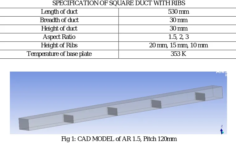
SPECIFICATION OF SQUARE DUCT WITH RIBS
Length of duct 530 mm
Breadth of duct 30 mm
Height of duct 30 mm
Aspect Ratio 1.5, 2, 3
Height of Ribs 20 mm, 15 mm, 10 mm
[image:3.612.114.496.221.457.2]Temperature of base plate 353 K
Fig 1: CAD MODEL of AR 1.5, Pitch 120mm B. CFD procedure
Computational flow domain: The computational flow domain of square duct with perforated ribs is designed with the help of geometry factors and the flow takes place inside the square duct as an air domain.
[image:3.612.109.496.520.712.2]1) Mesh Generation
TABLE II
MESH DETAILS of AR 1.5, PITCH 120mm.
Mesh type Tetrahedral mesh
Number of elements 62621
Number of nodes 13030
Technology (IJRASET)
C. Boundary Conditions [image:4.612.81.538.159.270.2]Boundary conditions are mentioned on computational domain of square duct with ribs. It is seen from fig 3 that the pressure gradually decreases from inlet to outlet and base plate temperature is at 353K.
Fig 3: Boundary conditions of square duct with perforates ribs
TABLE III
BOUNDARY CONDITIONS
Analysis type Inlet Steady state
Mass flow inlet 3.5 m3/min (0.875 m/s)
Inlet temperature 300 K
Outlet Pressure outlet
Wall boundary conditions Base Plate @ 353K
Fluid type Continuous fluid
Fluid properties:
Working fluid Air
Density 1.22 kg/
Viscosity 1.78e-5 kg/m-sec.
Thermal conductivity 1006 J/kg-K
IV. RESULTS AND DISCUSSION
A. For AR 1.5 and Pitch 120mm.
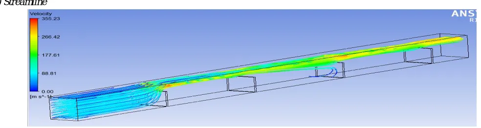
[image:4.612.48.540.560.691.2]1) Streamline
Fig 4: Streamlines coloured by Velocity, AR 1.5, Pitch 120
Technology (IJRASET)
high velocity and air passes out at high velocity from outlet. Maximum velocity achieved is 355.23 m/s.
[image:5.612.52.549.117.256.2]2) Temperature
Fig 5: Temperature plots along Plane-1, AR 1.5, Pitch 120
Figure 5 shows the temperature is maximum at the base plate and is at room temperature at upper plate. The temperature of around 315 K is obtained around the ribs as air passes the ribs.
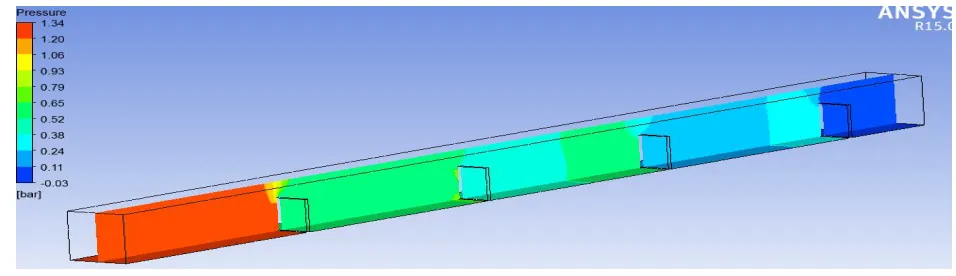
[image:5.612.64.542.328.466.2]3) Pressure
Fig 6: Pressure plots along Plane-1, AR 1.5, Pitch 120
Figure 6 shows pressures along plane. The pressure is maximum at the inlet as it strikes the ribs the pressure gradually decreases towards the outlet. The pressure varies from 1.34 bar to -0.03 bar from inlet to outlet.
[image:5.612.71.540.539.663.2]4) Velocity Plots
Fig 7: Velocity plots along Plane-1, AR 1.5, Pitch 120
Technology (IJRASET)
5) Heat fluxFig 8: Heat flux plots along Plane-1, AR 1.5, Pitch 120
Figure 8 shows heat flux along plane. Maximum heat flux in the domain found to be 57636 W/m². Due to the higher aspect ratio heat Flux distribution is not uniform throughout the base plate and heat flux is higher near the ribs.
V. CONCLUSIONS
CFD analysis is carried out to understand the flow behaviour and thermal characteristics rate of a square channel using rectangular ribs with varied Aspect ratios of 1.5, 2 and 3. Analysis is carried out for 120 mm and 240 mm pitch distances for all the 3 aspect ratios. Contours are plotted for Temperature, Pressure, Domain velocity and Heat flux at ZX plane and following conclusions were drawn.
A. It is observed that velocities are maximum in the domain for the aspect ratio of 1.5 due to obstruction in the channel. B. From pressure contours it is observed that higher the aspect ratio, lower the pressure drop in the channel.
C. Pressure drop in the domain for the Aspect ratio of 3 found to be very minimal and the air flow distribution found to be throughout the channel resulting better heat transfer rate.
D. From the above observations it could be concluded that higher the Aspect ratio and larger the pitch, lower the pressure drop and higher rate of heat transfer in the domain.
VI. ACKNOWLEDGEMENT
I wish to express my special gratitude to my guide Prof. Anandkumar.S.Malipatil, Department of Thermal Power Engineering, Dept., of PG Studies, VTU regional office, Kalaburagi for his inspiration constant supervision, direction and discussions in successful completion of this project.
REFERENCES
[1] AnandKumar S Malipatil et. al. (2015) “Experimental investigation of air flow characteristics in rectangular channel using pedestals as vortex generator” eISSN: 2319-1163
[2] K. Yongsiri et al. “Augmented heat transfer in a turbulent channel flow with inclined detached-ribs” International Journal of Heat and fluid flow(2014) [3] Prashanta Dutta et al. (2004) “Internal cooling augmentation in rectangular channel using two inclined baffles” International Journal of Heat and Fluid Flow 26
(2005)
[4] Boonloi and Withada et al. (2016) “Numerical investigation on turbulent forced convection and heat transfer characteristic in a square channel with discrete combined V-baffle and V-orifice” International Journal of Heat and Fluid Flow (2016)
[5] Monsak Pimsarn, et al. “Augmented Heat Transfer in Rectangular Duct with Angled Z-Shaped Ribs” PEA-AIT International Conference on Energy and Sustainable development: Issues and Strategies (ESD 2010)
[6] Liang-Bi Wang, Wen Qaun Tao, Qiu- Wang Wang, Tsun Tat Wang “experimental study of developing turbulent flow and heat transfer in ribbed convergent divergent aquare duct” International Journal of Heat and fluid flow 22(2001)603-613
[7] Giovanni Tanda, et al. Effect of rib spacing on heat transfer and friction in a rectangular channel with 45° angled rib tabulators on one/two walls”, International journal of Heat and Mass Transfer 54 (2011):1081-1090
[8] Skullong et al. ”Numerical investigation of cooling enhancement with internal ribs coolant film”, proceedings of ASME Turbo Expo 2012.
[9] Smith Eiamsa-ard et al. 2015 [6] “Heat transfer enhancement by helical tape coupled with rib turbulators" Journal of Mechanical Science and Technology 28(11): 4771-4779 (2015)