DISCLAIMER OF ALL WARRANTIES & LIABILITIES
Corvus Systems, Inc. makes no warranties, either expressed or implied, with respect to this manual or with respect to the software described in this manual, its quality, performance, mer-chantability, or fitness for any particular purpose. Corvus Systems, Inc. software is sold or licensed "as is:' The entire risk as to its quality or performance is with the buy~r and not Corvus Systems, Inc., its distributor, or its retailer. The buyer assumes the entire co* of all necessary servicing, repair, or correction and any incidental or consequential damages.' In no event will Corvus Systems, Inc. be liable for direct, indirect, incidental or consequential damages, even if Corvus Systems, Inc. has been advised of the possibility of such damages. Some states do not consequential damages, so the above limitation may not apply to you.
Every effort has been made to insure that this manual accurately documents the operation and servicing of Corvus products. However, due to the ongoing modification and 1:1pdate of the soft-ware along with future products, Corvus Systems, Inc. cannot guarantee the accuracy of printed material after the date of publication, nor can Corvus Systems, Inc. accept :responsibility for errors or omissions.
NOTICE
Corvus Systems, Inc. reserves the right to make changes in the product described in this man-ual at any time without notice. Revised manman-uals and update sheets will be published as needed and may be purchased by writing to:
Corvus Systems, Inc. 2029 O'Toole Avenue San Jose, CA 95131
Telephone: (408) 946-7700
TWX 910-338-0226
This manual is copyrighted and contains proprietary information. All rights reserved. This docu-ment may not, in whole or in part be copied, photocopied, reproduced, translated or reduced to any electronic medium or machine readable form without prior consent, in writing, from Corvus Systems, Inc.
Copyright© 1982 by Corvus Systems, Inc. All rights reserved.
Mirror® patent pending, The Corvus Concept,'" Transporter,'" Corvus OMNINET,'" Corvus Logica1c,'" Time Travel Editing,'" EdWord,'" Constellation,'" Corvus,'" Corvus Systems,'M Personal Workstation,'" Tap Box,'" Passive Tap Box,'" Active Junction Box,'" Omninet Unit'" are trademarks of Corvus Systems, Inc.
FCC WARNING
CORVUS DEALER SERVICE
CORVUS SYSTEMS
B-SERIES 5.25-INCH
6-MEGABYTE
WINCHESTER DISK DRIVE
SERVICE MANUAL
COVERING
REVISION A THROUGH REVISION E
PART NO,,: 7100-04703
PUBLICATION NO.: GEN/10.2-01/1.1 RELEASE DATE: JUNE 15, 1983
This document contains three types of notations. These are, in increasing order of importance, NOTE,
CORVUS DEALER SERVICE
CORVUS DEALER SERVICE
TABLE OF CONTENTS
List of Figures and Tables ... v
List of Assembly and Schematic Drawings. . . .. vi
Specifications . . . .. vii
CHAPTER 1 - GENERAL DESCRIPTION 1.1 Scope of Chapter. . . .. . . .. 1
1.2 Introduction ... " 1 1.3 Purpose of Equipment. . . .. . . .. . . .. . . .. . . .. . . .. . . .. . . .. 1
1.4 Model Identification. . . .. 1
1.5 Corvus [)isk System. . . .. . . .. . . .. . . .. . . .. 3
1.5.1 Power Supplies. . . .. . . .. . . .. . . .. . . .. 3
1.5.2 Data Backup ... ' ... 3
1.6 Winchester Disk Drive. . . .. . .. . . .. 5
CHAPTER 2 - INSTALLATION 2.1 Scope of Chapter ... 6
2.2 Introduction. . . .. 6
2.3 Receiving a Drive. . . .. 6
2.3.1 Diagnostic Test. . . .. 6
2.4 Environnlental Considerations ... 9
2.5 Daisy-Chaining of Disk Drives ... 10
CHAPTER 3 - OPERATION 3.1 Scope of Chapter ... 13
3.2 Introduction ... 13
3.3 Controls ... 13
3.3.1 Front Bezel LEDs ... 13
3.3.2 Front Bezel Switches ... 13
3.4 Power-On Sequence ... 14
3.5 Environrrlental Requirements ... 14
3.5.1 Static Electricity. . . .. 14
3.5.2 Line Noise ... 15
3.5.3 Temperature ... 15
3.6 Periodic Maintenance ... 15
3.6.1 Regular Checks ... 16
CHAPTER 4 - DRIVE DESCRIPTION 4.1 Scope of Chapter ... 17
4.2 Introduction ... ~ ... 17
4.3 Drive Revisions ... 17
4.3.1 Revision A Drive ... . . . .. 17
4.3.2 Revision B Drive ... 19
4.3.3 Revision C, D and E Drives . . . .. 20
4.4 General Description ... 20
4.4.1 Disk Sealed Mechanism ... 21
CORVUS DEALER SERVICE
4.4.2.1 CP134 (Rev A) ... 22
4.4.2.2 HB5 (Rev A) ... 22
4.4.2.3 CP417 (Rev B-E) ... 22
4.4.3 dc Power Cables ... 22
4.4.3.1 Rev A dc Cables ... 22
4.4.3.2 Rev B-E dc Cables ... 22
4.5 Controller Firmware ... 22
4.6 Data Storage ... 22
4.7 Transportation Considerations. . . .. 23
4.8 Theory of Operation ... 23
4.8.1 Power-Up ... 23
4.8.2 Con troller PCA ... 23
4.8.2.1 Controller During Seek Command ... 24
4.8.2.2 Controller During Read and Write Com~ands ... 24
4.8.3 Backplane PCA ... 24
4.8.4 Paddleboard PCA ... 24
4.8.5 Interface PCA ... 25
CHAPTER 5 - DISASSEMBLY 5.1 Scope of Chapter ... 26
5.2 Introduction ... 26
5.2.1 Tools Required ... 26
5.3 Metal Package. . . .. 26
5.3.1 Top Cover ... 26
5.3.2 Controller PCA ... 26
5.3.2.1 Rev A Drives. . . .. 26
5.3.2.2 Rev B Drives ... 26
5.3.3 Backplane PCA ... 27
5.3.3.1 Rev A Drives ... 27
5.3.3.2 Rev B Drives ... 27
5.3.4 Drive Mechanism ... 27
5.3.5 Power Supplies ... 27
5.3.4.1 Rev A Drives ... 27
5.3.4.2 Rev B Drives . . . .. 27
5.3.6 Front Bezel ... 27
5.4 Plastic Package ... 27
5.4.1 Top Cover ... ~ ... ~ ... 28
5.4.2 Controller PCA ... " ... 28
5.4.3 Backplane PCA ... " ... 28
5.4.4 Drive Mechanism ... 28
5.4.5 Power Supply ... " ... 28
5.4.6 Front Bezel ... : ... 28
CHAPTER 6 - ADJUSTMENTS AND MAINTENANCE 6.1 Scope of Chapter ... 29
6.2 Introduction ... 29
6.3 Power Supply Voltage Check and Adjustment ... 29
CORVUS DEALER SERVICE
6.3.1.1 Voltage Check (CP134) ... 29
6.3.1.2 Voltage Adjustment (CP134) ... 30
6.3.1.3 Voltage Check (HB5) ... 30
6.3.1.4 Voltage Adjustment (HB5) ... 30
6.3.2 Rev B Drives - Single Power Supply ... 32
6.3.2.1 Voltage Check (CP417) ... 32
6.3.2.2 Voltage Adjustment (CP417) ... 32
CHAPTER 7 - DEALER SERVICE DIAGNOSTICS 7.1 Scope of Chapter ... 33
7.2 Introduction ... 33
7.3 Drive Diagnostics. . . .. 33
7.3.1 CRC ... 33
7.3.2 EXR ... ' ... 34
7.3.3 UPD ... 34
7.3.4 VSN ... '.' ... 34
7.3.5 FMT ... 35
7.3.6 PRM ... 35
7.3.6.1 MUX ... 35
7.3.6.2 DRIVE ... 36
7.3.7 SET ... 36
7.3.8 QUIT ... 36
7.4 Controller Diagnostic ... 36
7.4.1 General Description ... 36
7.4.2 Controller Diagnostic Commands ... 37
7.4.2.1 A) Abort Diagnostic ... 37
7.4.2.2 B) Macro Menu ... 37
7.4.2.3 C) Change Slot Number ... 38
7.4.2.4 D) Download Diagnostic ... 38
7. 4. 2. 5 I) Analyze Servo. . . .. 38
7.4.2.6
J)
Single Do Seek ... 387.4.2.7 L) Full Cylinder Loopseek ... 38
7.4.2.8 P) Print Quiet Summary Report ... 38
7.4.2.9 Q) Sector Quiet Program ... 39
7.4.2.10 S) Read Scan Disk ... 39
7.4.2.11 T) Single Cylinder Seek Scan ... 39
7.4.2.12 X) Write Scan Disk ... 40
7.4.2.13 Y) Rezero Heads ... 40
7.4.3 Error Codes ... 40
7.5 Burn-In Program ... 40
7.5.1 C)ONT ... 40
7.5.2 L)IST ... 41
7.5.3 R)ESTART ... 41
7.5.4 Q)UIT ... 41
7.6 Read Burn-In Results ... 41
CHAPTER 8 - FAULT ISOLATION PROCEDURES 8.1 Scope of Chapter ... 42
8.2 Introduction ... 42
8.3 'fools ... 42
CORVUS DEALER SERVICE
8.4 Error Codes ... 42
8.4.1 Interpreting Error Codes ... 42
8.5 Troubleshooting Procedures ... 46
8.5.1 On-Site Checks ... 46
8.5.2 Isolate the Problem ... 46
8.5.3 Drive Not Ready ... 47
8.5.3.1 Interface ... 47
8.5.3.2 Controller Firmware ... 47
8.5.3.3 Power Supply Voltages ... 47
8.5.3.4 Drive Electronics ... 47
8.5.3.5 Drive Sealed Mechanism ... 48
8.5.4 Link Inoperative ... 48
8.5.4.1 Check Link Action ... 48
8.5.4.2 Power Supply ... 48
8.5.4.3 CRC Test ... 48
8.5.4.4 Controller Communication ... 49
8.5.4.5 Servo Action ... , ... 49
8.5.4.6 Controller Firmware ... , ... 49
8.5.4.7 Boot ROM ... 49
8.5.4.8 Interface Components ... 49
8.5.4.9 Drive Initialization ... 49
8.6 Final Adjustments and Tests ... 50
8.6.1 CRC Test ... 50
8.6.2 8.6.3 8.6.4 8.6.5 Appendix A Appendix B Appendix C Appendix D Install and Test Mirror ... 50
CRC Test ... 50
Power Supply . . . .. 50
Burn-In Test ... 50
Glossary ... 57
Parts List for B-Series 6MB Drives ... 59
B-Series 6-Megabyte Cabling Chart ... 60
CORVUS DEALER SERVICE
Figure 1·-1 Figure 1-2 Figure 1-3 Figure 2-1 Figure 2-2 Figure 2-3 Figure 2-4 Figure 2-5 Figure 2-6 Figure 2-7 Figure 3-1 Figure 3-2 Figure 4-1 Figure 4-2 Figure 4-3 Figure 4-4 Figure 6-1 Figure 6-2 Figure 6-3
Table 8-1 Table 8-2 Table 8-3
CORVUS DEALER SERVICE
LIST OF FIGURES AND TABLES
Figures
B-Series 6-Megabyte Drive (Revisions C-E) ... viii
B-Series 6-Megabyte Drive (Revision B) . . . .. 2
B-Series 6-Megabyte Drive (Revision A) . . . .. 4
MIRROR Switch Location. . . .. 7
MIRROR Switch Settings. ... . ... .... 7
Rear Bezel. . . .. 8
Disk Drive Installation . . . .. 9
Controller Address Switch Location ... 10
Controller Address Switches ... 11
Daisy-Chaining of Disk Drives . . . .. 12
Front Bezel Configuration Switches ... '. . . . .. 14
Single-User Front Bezel Switch Positions ... 15
Disk Drive Sealed Mechanism, . . . .. 18
Data Configuration. . . .. 19
Sector Interleaving ... 20
Disk Drive Contaminants ... 21
CIJ417 Power Supply ... 29
CIJ134 Power Supply ... 31
HBS Power Supply ... 32
Tables Decimal Disk Error Codes . . . .. 43
Hexidecimal Disk Error Codes ... 44
CORVUS DEALER SERVICE
CORVUS DEALER SERVICE
LIST OF ASSEMBLY AND SCHEMATIC DRAWINGS
Final Assembly (Rev A Drive) . . . .. 61
Final Assembly (Rev B Drive) . . . .. 62
Final Assembly (Rev C-E Drives) . . . .. 63
Drive Cover Assembly (Rev C-E Drives) ... 64
CORCOM Assembly (Rev C-E Drives) ... 65
CP134 Power Supply, Assembly (Rev A Drive) . . . .. 66
CP134 Power Supply, Schematic (Rev A Drive) . . . .. 67
HB5 Power Supply, Assembly and Schematic (Rev A Drive) ... 68
CP417 Power Supply, Assembly (Rev B-E Drives). . . .. . . .. . . .. .. . . .. 69
CP417 Power Supply, Schematic (Rev B-E Drives) ... 70
Read/Write PCA Phase 3, Schematic (Rev B-E Drives) ... (1 of 4) 71 Read/Write PCA Phase 3, Schematic ... ~ ... (2 of 4) 72 Read/Write PCA Phase 3, Schematic ... (3 of 4) 73 Read/Write PCA Phase 3, Schematic ... (4 of 4) 74 Read/Write PCA Phase 3, Assembly ... 75
Controller PCA Phase 3, Schematic (Rev B-E Drives) ... (1 of 6) 76 Controller PCA Phase 3, Schematic ... (2 of 6) 77 Controller PCA Phase 3, Schematic ... (3 of 6) 78 Controller PCA Phase 3, Schematic ... (4 of 6) 79 Controller PCA Phase 3, Schematic ... (5 of 6) 80 Controller PCA Phase 3, Schematic ... (6 of 6) 81 Controller PCA Phase 3, Assembly . . . .. 82
Read/Write PCA Phase 4, Schematic (Rev B-E Drives) ... (1 of 4) 83 Read/Write PCA Phase 4, Schematic ... (2 of 4) 84 Read/Write PCA Phase 4, Schematic ... (3 of 4) 85 Read/Write PCA Phase 4, Schematic ... (4 of 4) 86 Read/Write PCA Phase 4, Assembly ... 87
Controller PCA Phase 4, Schematic (Rev B-E Drives) ... (1 of 6) 88 Controller PCA Phase 4, Schematic ... (2 of 6) 89 Controller PCA Phase 4, Schematic ... (3 of 6) 90 Controller PCA Phase 4, Schematic ... (4 of 6) 91 Controller PCA Phase 4, Schematic ... (5 of 6) 92 Controller PCA Phase 4, Schematic ... (6 of 6) 93 Controller PCA Phase 4, Assembly . . . .. 94
Read/Write PCA Phase I, Schematic (Rev A Drives) ... (1 of 3) 95 Read/Write PCA Phase I, Schematic ... (2 of 3) 96 Read/Write PCA Phase I, Schematic ... (3 of 3) 97 Read/Write PCA Phase I, Assembly ... 98
Controller PCA Phase I, Schematic (Rev A Drives) ... (1 of 4) 99 Controller PCA Phase I, Schematic ... ~ ... (2 of 4) 100 Controller PCA Phase I, Schematic ... (3 of 4) 101 Controller PCA Phase I, Schematic ... (4 of 4) 102 Controller PCA Phase I, Assembly ... . .. 103
Backplane PCA Scllematic . . . .. 104
CORVUS DEALER SERVICE
Operational Specifications
Disks per Drive Disk Diameter (in/mm) Data Surfaces per Drive Heads per Surface Data Heads
Number of Data Cylinders/Drive Sectors per Track
Track Density (TPI)
Bytes per Sector (Formatted) Bytes per Track (Formatted) Bytes per Drive (Formatted) Bit Density, maximum (BPI) Average Latency (ms) Average Access Time (ms) Maximum Access Time (ms)
Maximum Access Time, single-track (ms) Data Transfer Rate (Kb/s)
Recording Format Rota tional Speed (RPM) Start Time (s)
Stop Time (s)
Physical Dimensions
Height (in/cm) Length (in/cm) Width (in/cm) Weight Obs/kgs)
Environmental Requirements
Operating Temperature (F/C) Non-Operating Temperature (F/C) Operating Relative Humidity (%) Non-Operating Relative Humidity (%) Operating Altitude (ft)
Operating Vibration (g) Non-Operating Vibration (g) Non-Operating Shock (g)
Power Requirements
Line Voltage, Domestic (VAC) Line Voltage, Foreign (VAC)
Power Consumption (Watts) Line fuse (Amperes)
for 100V-120V for 220V-240V
Reliability
Mean Time Between Failure (MTBF)
Maximum Repair Time
CORVUS DEALER SERVICE
SPECIFICATIONS
Rev A Rev B-E
2 2
5.25/133 5.25/133
4 4
1 1
4 4
144 144
20 20
200 200
512 512
10,240 10,240
5.9MB 5.9MB
8,800 8,800
N/A
6.25N/A
125N/A
240N/A
3960 960
MFM MFM
4,800 4,800
30 30
15 15
Rev A-B Rev C-E
5.25/13.3 5.75 114.6
15.0 I 38.1 15.0 I 38.1
14.5 I 36.8 12.0 I 30.5
500 to 1000 I 100 to 370
-400 to 1400 I -400 to 600
10 to 80 10 to 90
-1,000 to +10,000
0.1 (5 cps linear increase to 100 cps) 1.0 (2 cps linear increase to 100 cps) 5.0 for 5ms duration
100-120, 48Hz-62Hz, Single-Phase 220-240, 48Hz-62Hz, Single-Phase
Rev A Rev B-E
125 125
3.0 slow-blow 1.5 slow-blow
2.0 slow-blow 1.0 slow-blow
10,000+ operational hrs., within above requirements
CORVUS DEALER SERVICE
CHAPTER
1
General Description CORVUS DEALER SERVICE
Ll Scope of Chapter
CORVUS DEALER SERVICE
CHAPTER
1
GENERAL DESCRIPTION
General Description
This chapter outlines the purpose of the Corvus B-Series 6-Megabyte Disk Drives. A brief description and layout is included, as is a definition of Winchester technology.
L2 Introduction
This document contains instructions for maintenance and repair of the Corvus Systems B-Series 6-Megabyte, S.2S-inch disk drive. Repair procedures for all 8-inch drives and S.2S-inch H-Series drives (Model 6, Model II, and Model 20) are contained in separate service manuals. Repair procedures for networks and other Corvus equipment are covered in other Corvus service publications.
Corvus Disk Drive Product Line
A-Series Drives
8-Inch II-Megabyte drive (Revision A) B- Series Drives
8-Inch II-Megabyte drive (Revision B) 8-Inch 20-Megabyte drive (Revision B) S.2S-Inch 6-Megabyte drives (All) H-Series Drives
S.2S-Inch 6-Megabyte drives (All) S.2S-Inch 12-Megabyte drives (All) S.2S-Inch 18-Megabyte drives (All)
Corvus Level I Dealer Service is on a module-replacement basis, and this manual is written to address this policy. The B-Series 6-Megabyte drive has been manufactured in five revisions (A through E). These five drives were housed in one of two drive cabinets: the metal cabinet, and the high-impact, foam-injection plastic cabinet. Instructions for troubleshooting and repair for all of these drives are detailed in this document.
Also included in this manual is documentation for the Dealer Service Diagnostic Utilities supplied to each Corvus Servicing dealer. These utilities provide for burn-in/reliability testing, adjustment, and troubleshooting of all Corvus Disk Drives.
Installation and operation of the Disk Drive are not covered in detail in this manual. For instructions on installation and operation, see the Corvus "Disk Systems Installation Guide" and Corvus "Disk Systems User Guide."
L3 Purpose of Equipment
The Corvus disk drive is a high-speed, intelligent mass-storage peripheral disk device designed to provide the host microcomputer with storage of digital information for instant retrieval at the request of the host system. The Corvus disk system consists of the S.2S-inch disk mechanism, a Z_80™ Intelligent Controller, power supply, host interface electronics, and may be ordered with 34-pin interface flatcable and Corvus Utility diskettes.
L4 Model Identification
The Corvus 6-Megabyte disk drives may be broken down into two functional groups, each having different internal components within the cabinet. The first group consists of the Rev A drive, with the Rev B through Rev E drives making up the second group.
The Rev A and Rev B drives are packaged in the metal cabinet, while the Rev C drive uses a white plastic cabinet, and the Rev D and Rev E drives use a Concept-gray plastic cabinet. The drive type (capacity and revision) and manufacture date may be determined from the serial number tag.
General Description CORVUS DEALER SERVICE
CORVUS DEALER SERVICE General Description
Locate the serial number tag at the rear of the drive basepan. The following is a sample serial number to be found on a Corvus S.2S-inch, 6-Megabyte drive:
142-A3S0/M and is decoded below:
14 represents the week of manufacture (week 14) 2 represents the year of manufacture (2 for 1982) A represents the drive capacity (A=6MB)
.3S0 represents the serial number of that drive
/M represents that this drive was shipped with an internal Mirror installed
Whenever communicating with Corvus in reference to Corvus products, include the serial number of the equipment involved.
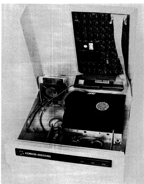
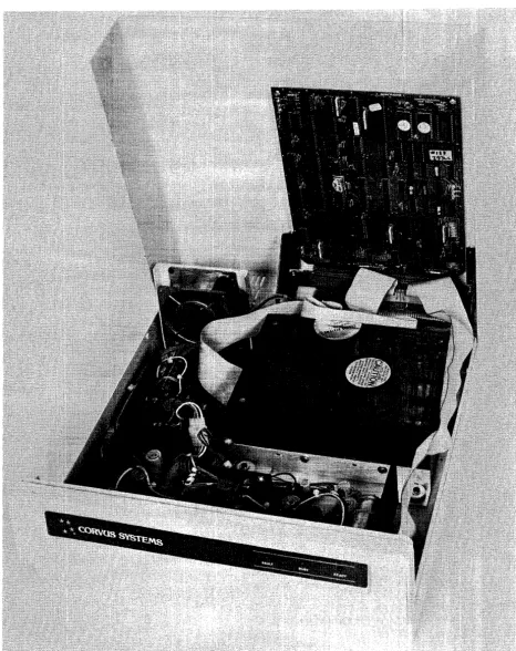
1.5 Corvus Disk Systems
The Corvus mass--storage disk system utilizes a sealed S.2S-inch Winchester disk mechanism manufactured by International Memories, Inc. (IMI)TM. The drive, with its Intelligent Controller, is designed as a plug-in device, requiring minimal software setup. Interfacing to host computers is via 34-pin flat cable interface. Installation and setup procedures are covered in the corresponding "Disk System User Guide" for the appropriate computer system. The Rev A drive consists of a S.2S-inch drive mechanism (with Read/Write PCA and Logic PCA), dual power supplies, Z-80 Controller PCA, and cooling fan mounted in the white metal cabinet. The later, Rev B drive consists of a different S.2S-inch drive mechanism (with Read/Write PCA), single power supply, Z-80 Controller PCA, and cooling fan mounted in the white metal cabinet. Rev C, Rev D and Rev E drives share these same components (as the Rev B), mounted in either a white (Rev C) or Concept-gray (Rev D and Rev E) cabinet.
Located in the bottom of the sealed unit is either one Read/Write PCA and one Logic PCA (Rev A drives) or one Read/Write PCA (Rev B through Rev E). These PC Assemblies are not field-serviceable items, and are not available as replacement parts. If the drive mechanism is diagnosed as defective, the entire drive sealed mechanism must be replaced.
The Mirror PCA (when installed) and the Z-80 intelligent Controller PCA are plugged into the two card slots of the backplane, inside the rear of the cabinet.
Although the Rev A and Rev B through Rev E drives are functionally identical (as far as the host microcomputer is concerned), no components are interchangeable, with the exception of the Mirror PCA.
1.5.1 Power Supplies
All 6-Megabyte drives operate from either 110-120VAC or 220-240VAC, SOHz or 60Hz single-phase power. Rev A drives have two power supplies and the Rev B through Rev E drives have a single power supply. These two different power supply configurations are not interchangeable.
1.5.2 Data Backup
Data backup is accomplished via the Corvus MIRROR™. The Mirror converts the data from digital format to video format which is then stored on video cassette tape, using one of many commercial VCRs. The Corvus Mirror option comes internal to the drive when it is ordered, or added as an external device later. Mirror troubleshooting and repair is covered in the Corvus Mirror Service Manual.
General Description CORVUS DEALER SERVICE
CORVUS DEALER SERVICE General Description
L6 Winchester Disk Drive
The Corvus disk drive uses the International Memories Inc. (IMI) Winchester disk mechanism. This new generation of disk drive utilizes a sealed environment, and low-load, low-mass, aerodynamically-suspended read/write heads which rest directly on the disk surface after powerdown. It is the contaminant-free environment that allows for reduction in clearance between head and recording media. This results in the heads riding on an 18-microinch air bearing, or air cushion" Since bit density is closely related to head-media clearance and head mass, disk drives utilizing Winchester technology can achieve large storage capacities at a premium of space. An added advantage of the Winchester sealed mechanism is that it requires no regular maintenance.
TMIMI is a registered trademark of International Memories Inc. ™ Z-80 is a registered trademark of Zilog, Inc.
™Corvus MIRROR is a registered trademark of Corvus Systems, Inc.
CORVUS DEALER SERVICE
CHAPTER
2
2.1 Scope of Chapter
CORVUS DEALER SERVICE
CHAPTER
2
INSTALLATION
Installation
This chapter discusses installation of the disk drive hardware as it applies to environmental requirements, to insure proper operation. Installation and operation procedures for the Corvus disk system are outlined in the "Corvus Disk Systems Installation Guide" and "Corvus Disk Systems User Guide."
2.2 Introduction
Upon receipt, each drive should be checked for shipping damage, and tested for proper function. This chapter contains these check-out procedures as well as those for installing single- and multiple-drive systems.
2.3 Receiving a Drive
Any time a drive is received, several checks should be performed before the drive is installed at the customer site. Each Corvus disk drive should be carefully unpacked and checked for shipping damage. External evidence of rough handling may be symptomatic of damage to fragile mechanisms within the drive.
NOTE:
Any damage claims must be reported to the local office of the shipper so an inspection may be made, and a damage report filed. If the damaged equipment is a new product, Corvus Order Processing Department must be contacted for proper return procedures.
If
the damaged equipment is a recently serviced product being returned under an RMA number (Return Merchandise Authorization number), contact Corvus Customer Service Department for proper return procedures.The disk drive mechanism in the Corvus Disk System is an extremely sensitive device. Subjecting the drive to a one-g force (one gravity) will be amplified and transmitted to the heads, impacting them onto the platter with a 100-g force. This necessitates very careful handling of the drive mechanism both in shipping and operation.
When a drive is received, check that all chips in the Z-80 Controller PCA are seated well in their sockets. Chips coming loose during shipping account for a large number of failures upon receipt.
1) Remove the screws securing the cabinet cover to the drive basepan (four on Rev A and B drives, two on Rev C, D and E drives), and remove the cover. Be careful not to stress the dc power cable and flatcables connecting the two halves of the drive cabinet.
2) Locate the Mirror PCA (if installed) plugged into the lower of the two card slots of the backplane, and remove it. 3) Locate the Controller PCA installed behind the Mirror PC A, and press firmly on all socketed chips, seating them
securely into their sockets.
4) Replace the Mirror PCA.
5) Replace the drive cover and secure it with screws.
2.3.1 Diagnostic Test
When a disk drive is received, its proper function must be verified. The following list of procedures provides a means of accomplishing this.
1) Verify the front bezel switch positions.
2) Verify the Mirror switch positions (on the rear of the drive).
3) Check Controller Firmware VERSION. 4) Check the power supply voltages. 5) Execute the CRC Test.
Installation CORVUS DEALER SERVICE
PROCESSOR
III
II DRIVE
II
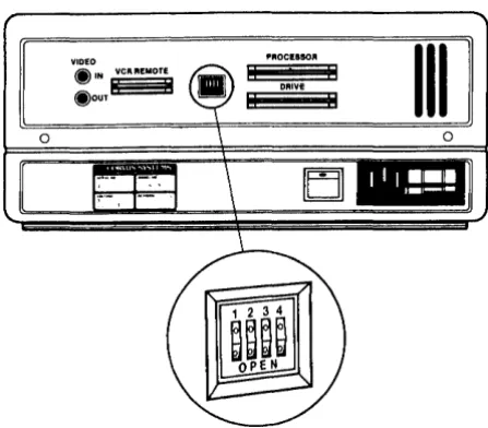
[image:24.615.198.422.144.340.2]EJ]
Figure 2-1. Mirror Switch Location
2 3 4 2 3 4
III
~./'/'---L-
Pushed in~~o
bJbJldo
OPEN
DRIVES WITH NO MIRROR OR EXTERNAL MIRROR:
OPEN DRIVES WITH PAUSECAM MIRROR:
OPEN
DRIVES WITH NTSC MIRROR:
[image:24.615.96.533.451.565.2]Shading indicates that the switch should be pushed in on that side.
figure 2-2. Mirror Switch Settings
6) Check the parameters (DRIVE and MUX) and record on paper. 7) Execute the EXERCISE utility.
8) Run the BURN-IN Diagnostic (this is DESTRUCTIVE to data on the drive).
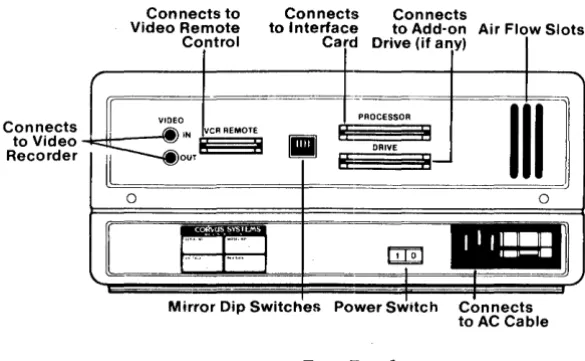
Connects to Video Recorder
CORVUS DEALER SERVICE
Connects to Connects Connects
Video Remote to Interface to Add-on Air Flow Slots
Control Card Drive (if any)
If VIDEO
PROCESSOR
III
1
MlIN VCR REMOTE
II
I: : I~o",l:
:1
DRIVE8
II0 0
II
..
llliil
r····
r-··
I ~,
... J'."'.'J
I,
,
MIrror DIp SWItches Power SWItch Connects
[image:25.615.168.461.115.295.2]to AC Cable
Figure 2-3. Rear Bezel
Installation
Any Corvus Disk Drive may be ordered with a Corvus Mirror PCA installed. In the S.2S-inch drive, the Mirror PCA plugs into the Backplane PCA alongside the Controller PCA, inside the cabinet cover. The drive has four DIP switches, located on the rear panel, which MUST be set to correctly reflect the internal Mirror configuration {whether installed or not}. If these switches are not set correctly, the drive may not function properly {refer to the chart above for proper switch configuration}. Drives using an external, or "Stand-Alone;' Mirror should use the "No Mirror Installed" switch combination.
Check the drive power supply voltages and adjust if necessary {refer to Chapter 6, "Adjustments and Maintenance" for details}.
Next, thoroughly test the drive, using the Dealer Service Diagnostics (as outlined in Chapter 7 "Diagnostics" of this manual). Execute a CRC-Format Check as well as verify the Drive Parameters (specifically the Spare Track Table and the Virtual Drive Offset Table). If either of these tables display values out of range, use the PARAMETERS diagnostic utility to reset them to their appropriate values.
A new drive may be shipped with up to four tracks spared. There are a total of seven spare tracks available, which leaves a minimum of three (and most likely more) for use in the field. When the Drive Parameters are first checked, the values should be noted, recorded on a label, and attached to the drive for future reference.
In the event that the drive format is disturbed in shipment, it may be necessary to reformat the drive. The FORMAT utility should be used only as a last resort. Using the PARAMETERS diagnostic utility, first try to restore the drive parameters before attempting the FORMAT utility. The FORMAT program will restore default parameters to the drive, and therefore necessitate re-initialization of these parameters with the original values (i.e. previously spared tracks).
Default parameters are:
Spare Track table: no tracks spared VDO table: Drive 1
=
0Interleave Spec: aU S.2S-inch, B-Series drives
=
12Be sure to check the drive parameters before and after formatting the drive. If the drive has ever had a track spared, the Spare Track table and VDO table may need reconstruction before the data is restored. Knowing which tracks are spared prior to formatting the drive will simplify this procedure. Note on the label, any future tracks spared.
Installation CORVUS DEALER SERVICE
2.4 Environmental Considerations
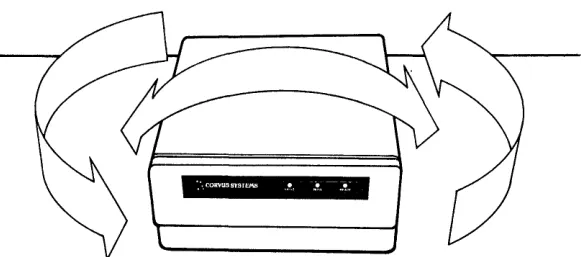
All electronic equipment needs cooling and the Corvus drive is no exception. When installing, do not "pigeon-hole" the drive. There should be sufficient open air both front and rear. Place the drive on a level, hard surface without foam or carpeting; the air intake slots are on the bottom of the cabinet, and must not be restricted. Do not place a video monitor on top of, or near the Corvus drive. Electromagnetic fields generated by this device may cause drive malfunction.
[image:26.613.162.453.226.355.2]:'. CORVUSSY5TEMB !I, ... T -::!~
Figure 2-4. Disk Drive Installation (Allow Ample Room Around the Drive Cabinet)
Be sure the proper line voltage has been selected and proper fuse size is installed.
Insure the interface cable is properly connected between the connector on the interface card in the host computer, and the PROCESSOR connector on the rear bezel of the Corvus disk drive cabinet. Be sure the "one" edge (edge with dark stripe) is to the right, when facing the rear of the drive unit.
Check that all four front panel switches are in the correct position. Run your finger along from right to left, under the switches. All switches should be to the left, unless the disk drive is connected to a Corvus Multiplexer Network system, or to a DEC LSI-IITM computer. In this case, the appropriate switches should be set.
CORVUS DEALER SERVICE Installation
2.5 Daisy-Chaining of Disk Drives
A maximum of four physical Corvus disk drives can be interfaced to the host computer. This is accomplished by using a common input/output interface bus, commonly refered to as daisy·-chaining. A maximum of 80 megabytes of on-line storage may be achieved by daisy-chaining four Model 20 drives. A special Corvus add-on drive flatcable is available specifically for this purpose. One add-on drive cable is required for each additional disk drive in the system.
All series and versions of disk drives may be daisy-chained together with the exception of the Rev A, 8-inch 11MB disk drive (Rev A drives may be daisy-chained only to other Rev A drives). When connecting H-Series drives in a daisy-chain, use controller firmware version CF18.3 (or newer) on all drives.
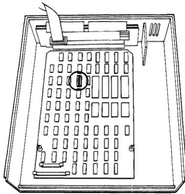
Changing the unit-select switches (positions 1-3) on the drive Z-80 Controller PCA for each add-on drive is required when daisy-chaining drives. New drives are shipped with the switches configured as drive 1. Additional drives should be set according to their position in the daisy-chain (2 through 7). Refer to the Corvus "Disk System User Guide" for the appropriate computer system.
For complete installation and initialization procedures, refer to the appropriate Corvus "Disk System Installation
Guide" and "Disk System User Guide:' .
00000000
OOm
OOOO
~B~DDDD
000000000
00000
000000000
o
0 ODD 0
0
WODDDO
[image:27.615.211.400.301.499.2]o
0 DOD
Figure 2-5. Controller Address Switch Location
™DEC and LSI-ll are registered trademarks of Digital Equipment Corporation
Installation CORVUS DEALER SERVICE
L'
/
1 2 3 4 5 6 7 8
~~
L - -_ _ _ _ _ _ _
V
~./---~/
1 2 3 4 5 6 7 8
~~
~
______
V
~~---,/
1 2 3 4 5 6 7 8
O~
t~~H'flln
~
______
I
~~---~/
1 2 3 4 5 6 7 8
~MM
L . . - - _ _ _ _ _ _
I
. / /
1 2 3 4 5 6 7 8
~~
V
/ " /
1 2 3 4 5 6 7 8
~~
V
~~---</
1 2 3 4 5 6 7 8
~nm-m
L . . - -_ _ _ _ _ _ /
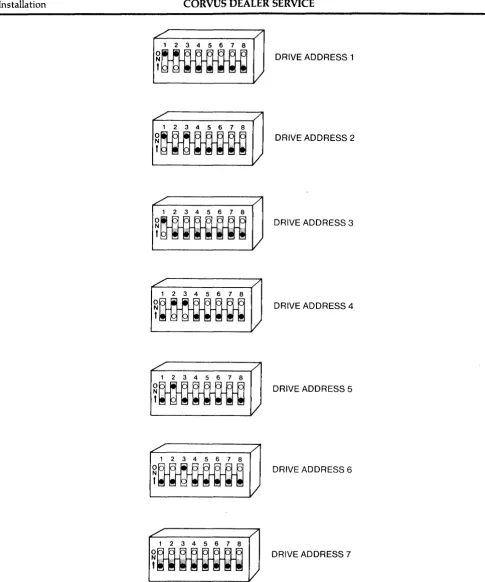
DRIVE ADDRESS 1
DRIVE ADDRESS 2
DRIVE ADDRESS 3
DRIVE ADDRESS 4
DRIVE ADDRESS 5
DRIVE ADDRESS 6
DRIVE ADDRESS 7
[image:28.615.63.549.66.649.2]Shading indicates that the switch should be pushed in on that side.
CORVUS DEALER SERVICE Installation
VIDEO @ IN VCR REMOTE
@OUT~ •
PROCESSOR
III
[image:29.617.194.418.188.496.2]o
Figure 2-7. Daisy-Chaining of Disk Drives
CORVUS DEALER SERVICE
CHAPTER
3
3.1 Scope of Chapter
CORVUS DEALER SERVICE
CHAPTER
3
OPERATION
Operation
This chapter describes operator controls and their use as applies to troubleshooting and repair of the drive. Front bezel control switches and Light Emitting Diodes (LEOs) are described, and their functions detailed. Environmental requirements are discussed, and recommended regular checks for the drive are given.
Operation and initialization instructions are detailed in the Corvus "Disk System User Guide" for the appropriate host operating system.
3.2 Introduction
All Corvus 5. 25-inch, 6-Megabyte drives have front bezel indicator lights and function switches. The switches must be set properly to reflect the system configuration in order for the drive to function correctly. Indicator LEOs on the front bezel display the state of the drive, and help in diagnosing the condition of the drive.
3.3 Controls
Operator controls are located on the front bezel of the enclosure. Three LEOs monitor the current state of the drive Controller. Four function switches are located under the LEOs. Rear bezel components consist of fuse and power selection unit (CORCOM), power switch, video connectors, Mirror configuration DIP switches, connectors for host processor, daisy-chained drive, and remote control VCR interface cables.
3.3.1 Front Bezel LEOs
The LEOs are labled READ~ BUS~ and FAULT. During the power-up sequence all LEOs are on, and BUSY blinks while the drive motor reaches operating speed. After the drive has completed the power-up sequence, the READY signal will be set, the READY LED will be on, and the BUSY and FAULT LEOs will be off.
During normal operation, the READY LED is active when the drive is ready to receive a command from the host processor. The BUSY LED is active when the drive is currently executing a command received from the host processor. The FAULT LED is active when command execution has been interrupted due to the occurrence of an error. The FAULT LED is an indicator of drive malfunction or operational error, although some software may cause this LED to light during normal operation. The FAULT LED function is accompanied by an error code displayed on the computer screen.
3.3.2 Front Bezel Switches
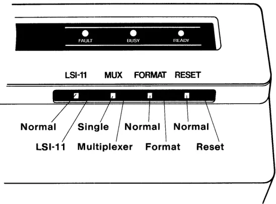
The function switches are located below the LEOs on the front bezel. These are (from left to right) LSI, MUX, FORMAf, RESET. During normal operation, in a single-user system without an LSI-II computer, all switches should be set to the left.
All switches except: for the RESET switch are software switches. The Controller ROM routine polls the switches to ascertain system configuration. Only the RESET switch directly affects the hardware. .
Located farthest to the left, the LSI switch is a two-position switch; the OFF (left) position is the normal position, the ON (right) position is for use with a DEC System LSI-II. At power-on time, the controller polls this switch. If a DEC LSI-II computer is attached, it loads the DEC RLOI™ and RLo2™ disk drive emulation routines from the Controller Firmware area into controller RAM.
The next switch, the MUX switch, is also a two-position switch; the OFF (left) position is the single-user position, the ON (right) position is for use with the Corvus Multiplexer Network TM. At power-on time, the controller polls this
switch to determine if a Multiplexer is attached. If a Multiplexer is connected, it then loads the Multiplexer polling routine from the Controller Firmware area into controller RAM.
Operation CORVUS DEALER SERVICE
•
•
•
FAULT BUSY nEADY
LSI-11 MUX
[image:32.612.179.453.100.302.2]LSI·11 Multiplexer Format Reset
Figure 3-1. Front Bezel Configuration Switches
The FORMAT switch is a two-position switch; left position is OFF (normal), right position is ON. This switch serves two functions. First, when the drive is turned on, the controller checks all front bezel switches. If the FORMAT switch is ON (right) at this time, the drive will come READY if the ROM-based self-test completes successfully. If, however, this switch is OFF, the controller reads the Controller Firmware from cylinders 0 and 1 into the on-board controller RAM. If this procedure is successful, the controller sets the READY signal, the READY LED is lit, and the BUSY and FAULT LEOs are extinguished. The drive is now ready to accept a command from the host system. Secondly, the FORMAT switch must be on for the diagnostic program F)ORMAT to execute (see chapter 7 "DIAGNOSTICS"). In this mode the switch acts only as a hardware safety switch. No one may execute the F)ORMAT program without having physical access to the drive. The switch being turned ON alone will not format the drive. Only the combination of the format software and the FORMAT switch will allow one to format the drive. If this switch is ON during normal operations, communication between the drive and the host system may be impaired.
Located farthest to the right, the RESET switch is a spring loaded, momentary-contact toggle switch. Toggling this switch initiates a reset signal which resets the intelligent controller in the drive to its original power-on state: the heads rezero and the disk Controller Firmware is again loaded from the disk intothe controller RAM. The drive is then ready to accept another command from the host processor.
3.4 Power-On Sequence
No specific sequence need be followed when powering on the Corvus Disk System, with one exception. If the Corvus
TM
disk drive is used with an OMNINET local network, power on the Disk Server first. Next power on the disk drive, then the host computer. This procedure supersedes all other procedures that may be found in previous Corvus publications.
3.5 Environmental Requirements
All working environments contain possible hinderances to proper operation of electronic equipment. The following are some environmental problems and their solutions.
3.5.1 Static Electricity
CORVUS DEALER SERVICE Operation
Static is most easily generated in a cool and dry enviromnent, usually associated with cold weather. Since increased humidity helps prevent static electricity buildup, some type of humidifying device can be helpful. Ideal relative humidity is 70 percent to 75 percent.
3.5.2 Line Noise
Electrical noise on the power line is a major cause of inconsistent equipment operation. Voltage spikes, "brownouts" and dropouts as well as low line voltage are just some of the common causes of drive malfunction.
ORVUS SYSTEMS • • •
II
[image:33.620.185.433.232.409.2]FAULT BUSY READY ,
Figure 3-2. Single-User Front Bezel Switch Positions
Located in the CORCOM power selection unit is a line filter capable of handling minor electrical noise on the power line. Also, the power supply is capable of handling dropouts of up to three complete power cycles.
If power is suspect, the problem may lie in poor continuity of the building wiring, noisy or high power-consumption devices on the same circuit, or poor external supply to the building. Power can be improved by including a constant voltage regulator or isolation transformer in the power circuit. The constant voltage regulator will help minimize the effect of line voltage fluctuations on the Corvus Drive, while the isolation transformer will be effective in protecting the Corvus Drive from line noise caused by other high-load electrical equipment such as photocopy machines, heating and cooling equipment, elevators, etc. To lessen the impact of frequent power interruption, the use of an uninterrupted power supply (UPS) is recommended.
3.5.3 Temperature
Although in most environments, the disk drive needs-no actual warm-up time, there are temperature limits that the drive must operate within (see specification chart at beginning of this manual). The temperature-change maximum for the Corvus disk is 15 degrees Fahrenheit per hour.
3.6 Periodic Maintenance
Inherent in the design of the Winchester technology disk devices, is the freedom from the need for regular preventive maintenance. The sealed disk mechanism of the Corvus disk drive requires no maintenance, and contains no field-serviceable components.
CAUTION:
Since contamination of the atmosphere in the mechanism necessitates replacement of the unit, removing the cover to the sealed mechanism voids all warranties.
Operation CORVUS DEALER SERVICE
3.6.1 Regular Checks
Each time the drive cabinet is opened, check the power supply voltages to verify that they are within specified tolerances (refer to chapter 6 for adjustment procedures). Power supply voltages will change with time, and should be checked periodically.
Due to slight oxidation buildup on cable connectors and
Ie
pins, reseating flat cable and power connectors and chips periodically will also help insure reliability.CORVUS DEALER SERVICE
CHAPTER
4
4.1 Scope of Chapter
CORVUS DEALER SERVICE
CHAPTER
4
DRIVE DESCRIPTION
Drive Description
This chapter provides a description of the components of the Corvus B-Series S.2S-inch, 6-Megabyte Disk Drive and their interactions. Some terms are defined to help provide a foundation for the descriptions.
4.2 Introduction
The Corvus 6-Megabyte Drive is divided into two basic revision groups: 1) Rev A Drive
2) Rev B through Rev E Drives
Each of these is further divided into three functional groups; Power Supply, Disk Sealed Mechanism, and Controller Electronics. These are defined as modules, and are field-replaceable as s,uch.
As mentioned elsewhere in this manual, five versions of the Corvus S.2S-inch, 6-Megabyte drive were manufactured. A drive may be identified by the revision noted on the serial numb.er tag located on the rear bezel.
4.3 Drive Revisions
All Revisions have:
- Disk Sealed Mechanism - Power Supply or Supplies -- Backplane PCA
- Con troller PCA
- Mirror PCA (if installed) - Paddleboard PCA - Drive Cabinet
4.3.1 Revision A Drive
The Rev A drive was shipped only in a metal drive cabinet, which contains the dual power supplies, as well as the early version sealed mechanism. This early disk mechanism can be identified by the two PCAs located on the underside of the sealed unit. The drive sealed mechanism, as well as the two PC As underneath it, is unique to the Rev A and may not be interchanged with units of another revision.
The Revision A drive uses two power supplies. All other Corvus drives use single power supplies. Neither of the Rev Ms power supplies is interchangeable with supplies of other revision Corvus drives. The dc power cable, originating at the power supplies, terminates with three power connectors which connect to the two pc boards underneath the drive mechanism, and the one on the Backplane PCA.
The Backplane PCA is attached to the drive cover with brackets. The Backplane has two card slots which accept the Controller PCA (nearest the cover) and the Mirror PCA (when installed). While physically similar, the Rev A Backplane is not interchangeable with other revisions of the 6-Megabyte drive.
LOGIC PCA
(REV A ONLy)
R/W PCA
HEAD-POSITIONING - STEPPER MOTOR
HEADSTACK
READ·WRITE HEADS
[image:37.792.66.732.100.483.2]BRUSH LESS DC DRIVE MOTOR
Figure 4-1. Disk Drive Sealed Mechanism
CORVUS DEALER SERVICE Drive Description
The Mirror PCA is located in the lower slot (farthest from the cover) of the Backplane PCA. The S.2S-inch Mirror is compatible with all versions of Corvus S.2S-inch disk drives. All Corvus 6-Megabyte drives have four DIP switches on the rear of the drive which MUST be configured to reflect the internal configuration of the Mirror PCA. If the drive has no Mirror PCA installed, the switches must be selected to reflect this configuration. Likewise, if a Mirror PCA is installed, the switches must be reset to reflect this change. See the table below for the proper switch settings.
External Mirror or No Mirror PAL/SWCAM Mirror NTSC Mirror
Switch 1
Closed
Closed Open
Mirror Switch Settings Switch 2
Closed
Open Open
Switch 3
Closed
Open Open
Switch 4 Closed
Open Open
The front bezel Paddleboard PCA contains the four function switches: FORMAT, RESET, MUX, and LSI-II, as well as three LEOs: FAULT, BUSY, and READY (see chapter 2 "Operation" for a full description of these components). The Paddleboard used on all S.2S-inch drives and on most 8-inch drives is compatible, and therefore interchangeable.
4.3.2 Revision B Drive
The Rev B drive retained the metal cabinet of the Rev A drive, but acquired all new internal components. The new drive sealed mechanism can be identified by the one Read/Write PCA located underneath the drive unit. This mechanism with its one Read/Write PCA is shared with the Rev B through Rev E S.2S-inch, 6-Megabyte drives, and are completely interchangeable.
The Rev B power supply is a single unit, the same one used in the later drive revisions supplying +12V and +sv, and is therefore completely compatible with the Rev C through Rev E drives. The Rev B power supply is not compatible with the Rev A model, and cannot be interchanged .
.",.---,.-
--/
"
~,
,.~
I ... - - ___ - - - - 1
I I
TRACK
PLATTER
I I
: , , _ - - - _ 1 -CYLINDER
( ' I
,
)
...
-
_ / [image:38.613.61.561.431.725.2]---
...Drive Description CORVUS DEALER SERVICE
The Rev B Backplane PCA is attached to the drive cover via standoffs. The Backplane PCA has two card slots which accept the Mirror PCA (when installed) and the Controller PCA (nearest the cover). The Rev B Backplane is the same one used in the Rev C through Rev E, B-Series 6MB drives and is interchangeable between these three later drive revisions. The Rev B Backplane PCA is not compatible with the Revision A drive and may not be interchanged. The Controller PCA is identical to the Rev C through Rev E, B-Series 6MB drives and is interchangeable between these four drive revisions. The Rev B Controller PCA is not compatible with the Rev A drive, and is not interchangeable.
The Mirror PCA used with 5.25-inch drives is interchangeable between all H-Series and B-Series drives of this size (5. 25-inch).
The front bezel Paddleboard PCA is the same PCA used in all revisions of the 5. 25-inch drive and most versions of the 8-inch drives, and is interchangeable between these drives.
4.3.3 Revision C, 0, and E Drives
With the exception of the cabinet, the Revision C drive is identical to the Revision B drive. The Rev C drive uses a white plastic cabinet, while the Rev 0 and Rev E drives use a gray plastic cabinet. Both drives contain the same components as the Revision B drive. Slight differences in mounting hardware may exist with the plastic cabinet, but all internal components of the Rev C, 0, and E drives are identical to the Rev B drive. (For details on the components of the Rev C, 0, and E drives, refer to the previous descriptions for the Rev B drive.)
4.4 General Description
[image:39.617.232.426.403.570.2]The recording media of the Corvus 5.25-inch Winchester disk drives consists of an nickel-oxide coating on aluminum disks called platters. There are two 5.25-inch platters in all B-Series 6-Megabyte drives, all four surfaces being utilized for data storage. One head rides above each surface on an 18-microinch air bearing (air cushion).
Figure 4-3. Sector Interleaving
Data is stored magnetically on circular tracks, which are configured as concentric circles on each platter. Each track is further divided radially into 20 sectors, each sector containing one 512-byte block of user data. The term track refers to a single head surface of a cylinder, each cylinder consisting of one track from each surface (four total), in common vertical alignment. There are 144 cylinders on the 5.25-inch, B-Series 6-Megabyte drive, with cylinder zero located farthest from the platter center.
A block is the smallest addressable quantity of data within the drive. Internally, each block consists of 512 bytes of data. Externally, the drive handles data in sectors as defined by the host computer.
CORVUS DEALER SERVICE Drive Description
Typically, each host operating system defines a sector as 128 bytes, 256 bytes or 512 bytes. The Corvus interface software uses the appropriate read and write commands (one each for writing and reading 128, 256 or 512 bytes) depending on the type of operating system.
This does not cause a conflict, since the drive simply stores 1,2 or 4 host-defined sectors for each block. Read and write commands of less than 512 bytes are transparent to the host system, due to the Intelligent Controller's ability to handle data blocking internally.
4.4.1 Disk Sealed Mechanism
The Corvus mass-storage disk mechanism uses a combination of both new Winchester technology and traditional disk design.
The 5.25-inch platters revolve on a common spindle, driven by a brushless dc motor at a speed of 4800 RPM. Motor speed is monitored and automatically adjusted at the motor, and is independent of line frequency. A sector disk is located at the lower end of the spindle, and is monitored by an LED and phototransistor which provide sector pulses to the drive electronics. A solenoid brake contacts the motor hub after po~er-off.
Each head glides 18-microinches (18 millionths of an inch) from the platter surface on an air bearing, or air cushion. A particle of smoke or dust, or a human hair could easily play havoc with with these critical tolerances, and cause catastrophic failure of the disk device. The seal on the drive cover keeps the internal atmosphere contaminant-free. BREAKING THIS SEAL FOR ANY REASON, VOIDS ALL WARRANTIES.
The heads are held by flexure arms, attached to a common head stack casting which moves on precision bearings and stainless steel rails. Positioning of the heads over the appropriate cylinder is done by a three-phase stepper motor, connected to the head stack by a stainless steel band. Seeking to a specific cylinder is accomplished by stepping the motor through three phases for each cylinder. Simply reversing the sequence of these motor phases will result in reversing the direction.
FLYING HEAD HEIGHT 20 MICRO-INCHES
SMOKE PARTICLE 250 MICRO-INCHES
I
HUMAN HAIR.003 INCHES
,
/OXIDE COATING 50 MICRO-INCHES
[image:40.617.59.551.451.720.2]DISK INTERIOR
Drive Description CORVUS DEALER SERVICE
Mounted beneath the drive mechanism is either one PCA (Revision B through Revision E drives) or two PCAs (Revision A drives). These are the Logic PCA, and the Logic PCA and Read/Write PCA, respectively. Since these are considered integral components of the sealed mechanism, individual replacements for these PC As are not available. If either of these PCAs are diagnosed as defective, the entire disk mechanism must be replaced.
4.4.2 Power Supply
Every Corvus 6-Megabyte Drive comes with a power supply(ies) to provide all voltages required by the drive mechanism and drive electronics. The two drive groups (Rev A, and Rev B through Rev E) have different drive mechanisms which require different voltages. The Rev A drive mechanism requires + 12Y, -12Y, +SY, and -SY, while the Rev B through Rev E drive mechanism requires only +12V and +SY.
4.4.2.1 CP134 (Rev A)
The CP134 is a black, open-chassis power supply (the larger of the two Rev A power supplies), which provides the +12Y, -12V and -SV voltages required by the drive. All three voltages are adjustable. The CP134 is mounted in the metal drive cabinet, along with the HBS power supply.
4.4.2.2 HBs (Rev A)
The HBS is the smaller of the two power supplies mounted in the Rev A metal cabinet, and provides +sV required by the drive. The +SV is adjustable.
4.4.2.3 CP417 (Rev B through Rev E)
The CP417is the only power supply required by the Rev B through Rev E 6-Megabyte Drives. Providing the +12Vand +SV required by the drive components, the CP417is used in the metal cabinet (Rev B) and the plastic cabinet (Rev C, 0, and E) drives.
4.4.3 de Power Cables
All power supplies connect to a de power cable which then connects to the disk mechanism and the drive Backplane PCA. All dc power cables attach to solder terminals on the power supply PCB.
4.4.3.1 Rev A de Cables
The Rev A power cable connects the two power supplies with the two PCAs on the underside of the drive mechanism, as well as the Backplane PCA connector. The power connectors for these PCAs are paralleled, and are interchangeable. These are polarized, to assist proper connection.
4.4.3.2 Rev B through Rev E dc Cables
In later drive revisions, the power supply cable connects the single power supply to the single PCA on the underside of the disk mechanism, and to the Backplane PCA. The power connectors are also polarized, to assist proper connection.
4.S Controller Firmware
Corvus reserves the first two cylinders of the drive for system information. This is referred to as Controller Firmware, and is not accessible to the host operating system. This firmware contains programming and system parameters needed by the 2-80 drive controller which is loaded into the disk drive RAM when the drive is powered on or the RESET switch is toggled. The MIRROR driver routines, spare track table, Multiplexer parameters and Semaphore status flags are a few examples of Controller Firmware. Identical copies of Firmware reside in each of the two cylinders. The rest of the disk area is available to the host system for data storage, the configuration of which depends upon the type of host operating system.
4.6 Data Storage
Data storage arrangement is by concentric tracks aligned in vertical cylinders. Each track is sectioned into 20 sectors, each sector has a capacity of S12 eight-bit bytes. Logical sectors are numbered by using an interleaving specification of twelve (for the B-Series, S.2S-inch drives), except for use with the DEC LSI-II which uses an interleaving specification of six (B-Series drives only).
CORVUS DEALER SERVICE Drive Description
All four surfaces are used for data storage. All four heads transfer digital information to and from the platters. Contained in the head stack is the microchip. This head select and driver microcircuitry is responsible for selecting which head is being used, and transmitting the signal to the drive electronics for further amplification.
4.7 Transportation Considerations
The Corvus B-Series 6-Megabyte, 5.25-inch Disk Drive has no locking device for the head carriage. This requires one careful consideration before transporting the drive; after powering off the drive, wait for the motor to stop spinning before moving the drive.
When the drive is powered off, the heads will not move. This means that heads rest on the data area of the media when the drive is shipped. If, when the drive is transported, it is subjected to rough handling, the heads will impact the disk surface in a critical area, possibly causing damage to the media. Gentle handling of the drive is essential for the drive to survive shipping.
4.8 Theory of Operation
The Revision A, and Revisions B through E 6-Megabyte, 5.25-inch drives are, though physically dissimilar, functionally similar. Controller Firmware version CF15.00r greater," and all associated drive initialization utilities, may be used.
4.8.1 Power-Up
As soon as the power supply voltages have stabilized, the Z-80 Controller board begins a routine which initializes the Z-80 microprocessor, and then executes a ROM-based self-test. The test checks the on-board RAM, and then a bit-sum check is done to the ROM. If the self-test fails, the Z-80 halts execution, leaving the FAULT and BUSY LEOs on, and READY LED off.
If the self-test executes successfully, the drive begins the firmware boot routine. This consists of first rezeroing the heads, bringing them over the first cylinder of the disk surfaces. The FORMAT switch is then sampled. If the switch is on, the Controller sets the READY signal. If it is off, the Controller Firmware is read from the first cylinder into the on-board RAM. If the firmware is successfully read the drive comes READY. If a bad block is encountered while reading the firmware, the Controller will attempt to read from the second copy any bad sectors found in the first. It will continue to read alternate copies from the disk until all Controller Firmware is successfully loaded into the Controller RAM.
4.8.2 Controller PCA
The Z-80 Drive Controller is responsible for interpreting commands sent from the host computer system and controlling the sub-assemblies; drive mechanism (with its Logic and/or Read/Write PC A) and Mirror PCA (when installed). The Controller reports back to the host computer the success of the command executed by means of a return code. During a write command, the Controller generates CRC bytes for each block of data written, and checks the block against the CRC value during the read command.
The Controller PCA contains the Z-80 CPU and support logic as well as Controller ROMs (containing procedural Z-80 code for the Intelligent Controller) and on-board RAM (used for buffering data to and from the disk, and utility code loaded from the Controller Firmware area of the disk). Also, four Z-80 PIa ICs are used to buffer signals to and from the Corvus Mirror, Multiplexer Network, and drive sealed mechanism. In addition, the CRC generatorlchecker error signal is monitored by one of the PIa ICs, and informs the Z-80 CPU in the case of a CRC error.
Drive Description CORVUS DEALER SERVICE
4.8.2.1 Controller During Seek Command
When the drive is requested to read or write a specific sector, the Controller first verifies the sector address as valid. Next, the Read/Write PCA is then commanded to strobe the stepper motor windings (phase 1-4). The Controller decrements the cylinder count one for each full motor phase sequence (1-4) and halts the stepper motor at the appropriate cylinder. The next sector to move past the heads is read to verify the success of the seek. If the incorrect cylinder was reached, the heads are rezeroed and the seek is attempted again. If the seek fails during the retry, the drive halts operation, and an error is returned to the host operating system.
4.8.2.2 Controller During Read and Write Commands
The write command begins when the command is received, along with the sector address(es). The Z-80 Controller determines whether the write command is for 128, 256 or 512 bytes, and relinquishes control to the DMA circuitry for transfer of the data from host memory to the onboard Controller RAM.
During host-to-drive transfer, the processor is put into a wait state while the DMA circuitry transfers the data from the host memory to the on-board RAM. The DMA circuitry uses the Z-80 processor as an address counter, and when the first byte is received from the host system, the DMA circuitry uses the address specified by the Z-80 to write the byte into on-board RAM. Between data byte transfers, the Z-80 is released from its wait state just long enough to increment its address counter.
Once the data is in RAM, control is returned to the Controller which performs a seek to the appropriate cylinder, if necessary, and reads the first available header to verify the seek. The DMA circuitry clears the CRC generator/checker, and waits for the proper sector to pass under the head. If the required write function is less than 512 bytes, the block is read in from the sector and the host information is overlaid into the appropriate locations of the block.
Next, preparations are made for writing that block out to the disk. When the proper sector comes around, the Controller again turns control over to the DMA circuitry. The Drive processor again is put into a wait state while the DMA transfers data bytes one at a time to the parallel-to-serial converter. A CRC value is generated from the serial data and inserted in the data stream, and both are then sent to the read/write circuitry for output to the heads. The CRC information is used for checking data integrity when read from the disk.
The disk write operation is concluded by reading in the block to verify its success. The bus direction is then reversed, and a status byte (return code) is sent to the host system indicating the result of the disk write.
4.8.3 Backplane PCA
The Backplane PCA is responsible for transferring power and signals between the Controller PCA, Mirror PCA, Paddleboard PCA, and the Host Interface PCA (via the rear bezel 34-pin connector). The upper slot of the Backplane is reserved for the Controller PC A, and the lower slot is reserved for the Mirror PCA. These two PCAs may not be in terchanged.
This two-piece PCA accepts flat cables from the front bezel Paddleboard PCA and the Drive Sealed Mechanism (Revision A only), as well as from the host computer System. A single dc power cable supplies voltage to the Backplane PCA via a four-pin connector.
The Backplane PCA for the Revision A drive is unique to that revision, and is not interchangeable with other revision drives. The Backplane PCA for the Revision B through E drives use the same Backplane PCA and is interchangeable between those four drives, but cannot be used in the Revision A drive.
4.8.4 Paddleboard PCA
The Paddleboard PC A, located on the front bezel of the drive enclosure contains switches and LEOs. The functions of these controls are detailed in chapter 2.
All Paddleboard PCA revisions are compatible with all drive revisions, and are interchangeable.
CORVUS DEALER SERVICE Drive Description
4.8.5 Interface PCA
The Corvus disk system may be configured for any of several different microcomputer systems, and may be purchased with one of many Corvus interface cards available.
The typical interface card contains address decoding, bidirectional data buffering, and handshaking circuitry. Some interface cards also have ROMs with boot routines for booting the microcomputer from the Corvus disk. Some do not, and these computers must boot from floppy diskette.
Connected to the 34-pin flat cable, the Interface PCA contains two input ports, and one output port and address decoder. One input port is an eight-bit tri-state data buffer, used for receiving data bytes during drive-to-host transfers. The other input port is the status port, used for determining the state of the disk drive. The output port is an eight-bit latch, used in host-to-drive data transfers.
When the host system needs to access the disk, it first checks the BUS DIRECTION signal, and if the bus is in the host-to-drive direction, and the READY signal is high, the drive is ready to accept a new command. The host now sends command bytes to the drive.
CORVUS DEALER SERVICE
CHAPTER
5
5.1 Scope of Chapter
CORVUS DEALER SERVICE
CHAPTER
5
DISASSEMBLY
Disassembly
With the possible exception of the cooling fan and Backplane PCB, the Revision A, and Revisions B through E drives' configurations differ significantly. Therefore, separate disassembly instructions are given for each of these two configurations.
These two configurations were installed in different cabinet designs. Disassembly of the metal cabinet drives is covered in section 5.3, while the plastic cabinet drives are covered in section 5.4.
5.2 Introduction
The Corvus B-Series 6-Megabyte 5.25-inch disk drives were manufactured in two basic functional revisions: the Rev A, and the Rev B thru Rev E. These drives were delivered in two basic packages: the white metal cabinet, and the narrower white or gray high-impact plastic cabinet. All Rev A and Rev B drives were delivered in metal cabinets, while Rev C drives used the white plastic case. The Rev 0 and Rev E drives are identical to the Rev C, except the case color
has been changed to grey. .
WARNING:
Before disassembling any disk equipment, be sure power Is disconnected.
5.2.1 Tools Required
The following tools are required for disassembly of the Corvus Revisions A through E 6-Megabyte drives: 1) #2 phillips screwdriver
2) 5/64-inch hex allendriver 3) 9/64-inch hex allen driver 4) 1/4-inch nutdriver 5) 5/16-·inch nutdriver
5.3 .Metal Package
The Rev
A
drive components differ from the Rev B components, but both use the white metal cabinet. The following instructions cover both metal packages; differences between the revisions are noted.5.3.1 Top Cover
1. Remove the six screws securing the top cover to the basepan.
2. Remove the cover straight up, being careful not to stress the ac wiring and flat cables connected to the cover.
5.3.2 Controller PCA 5.3.2.1 Rev A Drives
1. Remove the two screws securing the Controller PCA to the cover. 2. Remove the PCA by gently pulling it out of the Backplane slot.
5.3.2.2 Rev B Drives
1. Remove the drive mechanism flat cable from the upper connector of the Controller PCA noting its orientation. 2. Remove the two allen screws securing the PCA to the cover.