INVERTER CONTROLLER USING SYNCHRONOUS GENERATOR MATHEMATICAL MODEL
AHMED IBRAHEM NUSRAT
A project report submitted in partial
Fulfillment of the requirement for the award of the Degree of Master Electrical Engineering
Fakulti Kejuruteraan Elektrik dan Elektronik Universiti Tun Hussein Onn Malaysia
CHAPTER 1
1.1 Introduction
DC-AC converters are knows as inverters. An inverter is an electrical device that converts direct current (DC) to alternating current (AC), and this alternated power can be maintained in any frequency or voltage with the use of appropriate transformers, circuits and switches. Follow the lines to know about the advantages of inverters in our day to day life. The function of the inverter is to change a DC input to a symmetric AC output of desired magnitude and frequency. The output could be fixed or variable at a fixed or variable frequency. Variable output can be obtained by varying the input DC and maintaining the gain of the inverter constant. The inverter gain may be defined as the ratio of the AC output voltage to DC input voltage.
semiconductor devices the distortion contents of output voltage can be minimized or reduced significantly by switching techniques.
Inverter can be broadly classified into types. First single phase inverter and second three phase inverter. Also can be classified depending on the kind of the source of the feeding to voltage source inverters (VSI) and current source inverters (CSI).
Three phase inverters are normally used for high power applications. Three signal phase half or full bridge can be connected a three phase output can be obtained from a configuration of six transistors two types of the control signals can be applied to the transistors conduction or conduction. The conduction has
better utilization of the switches and is the preferred method.
There are many controller systems use in the inverter controller such as Proportional-Integral controller (PI controller), Proportional, Integral, and Derivative (PID controller) and fuzzy logic. The proposed of PI controller is to improve the performance of the soft switched inverter. The duty ratio of the inverter is controlled by PI controller. To provide optimal performance at all operating conditions of the system PI controller is developed to control the duty ratio of the inverter.
The PID controller algorithm involves three separate constant parameters, and is accordingly sometimes called three term control: the proportional, the integral and derivative values, denoted P, I, and D. Simply put, these values can be interpreted in terms of time: P depends on the present error, I on the accumulation of past errors, and D is a prediction of future errors, based on current rate of change [4]. The weighted sum of these three actions is used to adjust the process via a control element such as the position of a control valve, a damper, or the power supplied to a heating element.
logic, which operates on discrete values of either 1 or 0 (true or false, respectively) [3].
The alternator is a machine which produces alternating electricity. It is a kind of generators which converts mechanical energy into electrical energy. It is also known as synchronous generator (SG). Synchronous machines include alternators and motors which run at a constant speed in synchronism with the alternating current supply to which is connected. An alternator is a machine which has a stationary conductor system called stator and a rotating field system called rotor. The arrangement is very helpful to collect heavy currents at high voltages from stationary terminals.
Synchronous machine has two mechanical parts; a rotor and a stator. There are also have two electrical parts to the machine; a field source and an armature winding. These basic fundamentals of an electric machine are like those for a DC machine, with one significant difference. The field source of a synchronous machine is on the rotor, the armature winding of a synchronous machine is on the stator. Like DC machines, the field source creates a magnetic field the armature winding has a voltage induced in it by the field. Also like DC machines, the field can be produced using either a field winding or by using permanent magnets. Permanent magnet (PM) machines are common in small sizes, whilst large machines are usually made with field windings. Permanent magnet (PM) synchronous motors are widely used in low and mid power applications such as computer peripheral equipments, robotics and adjustable speed drives.
Figure 1.1: Project block diagram
1.2 Problem Statement
1.3 Project objectives
The objectives of this project are:
1- To design the inverter control using synchronous generator model. 2- To develop the current control for inverter control.
3- To investigate the current response at the load connection.
1.4 Scope of project
This project primarily development a new control strategy using mathematical model of SG in the inverter (DC-AC). In order to achieve these scopes of this project are:
1- The synchronous inverter control using synchronous generator equation will be designed in the MATLAB.
2- The modelling of current controller that suitable for DC-AC in order to control the current output is designed using MATLAB.
CHAPTER 2
LITERATURE REVIEW
2.1 Synchronous Generator
Synchronous generators are the primary source of all the electrical energy. It is known as synchronous machines because it operates at synchronous speed where the speed of rotor always matches supply frequency. These machines are the largest energy converters in the world. Where if converts mechanical energy into electrical energy.
enduring magnet engine is controlled by its rotor position such that the stator area is habitually (electrical) ahead of the rotor, the motor presentation can be very close to the accepted scrubbed DC engines, which is very much highly rated for variable hasten drives. The rotor place can be either noticed by utilising rotor place sensors or deduced from the induced emf in the stator windings. Since this type of motors does not need paint brushes, as are known as brushless DC engines [5].
2.2 Synchronous Machine Structures
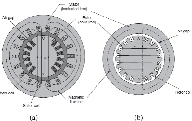
2.2.1 Stator and Rotor
Armature winding of alternators is different from that of DC machines. Basically three phase alternators carry three sets of windings arranged in the slots in such a way that there exists a phase difference of between the induced e.m.f.s in them.
In a DC machine, winding is brought out. In three phase alternators winding is open to two ends of each of set of winding is brought out. All the coils used for one phase must be connected in such a way that their e.m.f.s help each other. And overall design should be in such a way that the waveform of an induced e.m.f is almost sinusoidal wave form.
[image:8.595.162.470.507.701.2](a) (b)
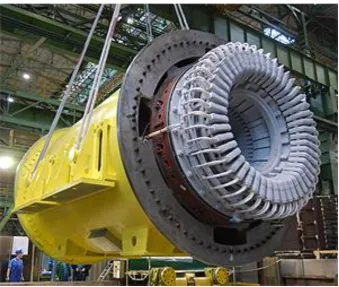
Figure 2.2: Stator of a 190-MVA three phase 12-kV 375 r/min hydroelectric generator. The conductors have hollow passages through which cooling water is
circulated (Brown Boveri Corporation)
[image:9.595.124.518.478.703.2]
Figure 2.4: End view of the stator a 26-kV 908-MVA 3600 r/min turbine generator with water-cooled winding. Hydraulic connections for coolant flow are provided for
each winding end turn (General Electric Company)
2.3 Synchronous Machines
The synchronous machines are classified into two types based on type of rotor used in construction. Synchronous machine rotor types:
1. Salient pole rotor: the individual rotor poles protrude from the center of the rotor, characterized by concentrated windings, non-uniform air gap, larger rotor diameters, used in applications requiring low machine speed and a large number of machine poles (example, hydroelectric generation).
2. Cylindrical rotor: the individual rotor poles are produced using a slotted cylindrical rotor, characterized by distributed windings, nearly-uniform air gap, smaller rotor diameters, used in applications requiring high machine speed and a small number of machine poles, typically 2 or 4 poles (example, steam or gas turbine generators).
The cylindrical rotor is typically a solid piece of steel (made from a single forging) for reasons of strength given the high rotational speeds to which the rotor is subjected. The salient pole rotor does not provide the mechanical strength necessary for these high speed applications. Also, the salient pole rotor presents too much wind resistance when rotating at high speeds [5].
2.3.1 Electrical Part
The field and the identical stator windings are distributed in slots around the periphery of the uniform air gap. The stator windings can be regarded as concentrated coils having self-inductance and mutual inductance
with a typical value , the negative sign is due to the phase angle), as shown in
Figure 2.5. Field (or rotor) winding can be regarded as a concentrated coil having self-inductance . Mutual inductance between the field coil and each of the three
Figure 2.5: Structure of an idealized three-phase round-rotor SG modified
where . The flux linkages of the windings are
where , and are the stator phase currents and is the rotor excitation current.
Denote
[
( )
] [
( )
]
Assume for the moment that the neutral line is not connected, then
(2.1)
It follows that the stator flux linkages can be rewritten as [1].
(2.2)
where = , and the field flux linkage can be rewritten as [1].
(2.3)
As it has been noted that the second term ( , ) (called armature reaction) is constant if the three phase currents are sinusoidal (as functions of ) and balanced.
To remind also mention that √ ( , ) is called the d-axis component of the
current.
Assume that the resistance of the stator windings is ; then, the phase terminal voltages = can be obtained from (1) as [1].
(2.4)
where = is the back electromotive force (EMF) due to the rotor movement given by [1].
The voltage vector is also called no-load voltage or synchronous internal voltage. From equation (2), the field terminal voltage is [1].
(2.6)
where is the resistance of the rotor winding. However, do not need the expression
for because will be use instead of as an adjustable constant input. This completes the modelling of the electrical part of the machine.
2.3.2 Mechanical Part
The mechanical part of a three phase synchronous generator consists mainly of a rotor core. The mechanical part of the generator is used to input mechanical power to the machine and its dynamic behavior affects the machines performance. In this part, the differential equations of the mechanical part of a three phase synchronous [8].
̈ ̇ (2.7)
where is the moment of inertia of all the parts rotating with the rotor, is the mechanical torque, is the electromagnetic torque, and is a damping factor.
can be found from the energy stored in the machine magnetic field, i.e [8].
From simple energy considerations:
|
Because constant flux linkages mean no back EMF, all the power flow is mechanical. It is not difficult to verify using the formula for the derivative of the inverse of matrix function that this is equivalent to [8].
|
Thus
(2.8)
To mention that √ is called the q-axis component of the current. Note that if or some arbitrary angle , then
Note also that if is constant (as is usually the case), then (2.8) with (2.5) yields
2.3.3 Per Phase Equivalent Electrical Circuit Model
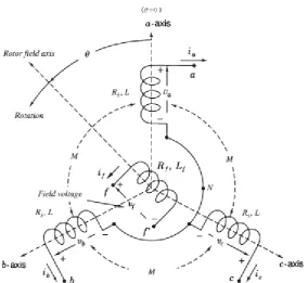
Figure 2.6 shows schematically the cross section of a three phase, two pole cylindrical rotor synchronous machine. Coils (aa', bb', and cc') represent the distributed stator windings producing sinusoidal mmf and flux density waves rotating in the air gap. The reference directions for the currents are shown by dots and crosses. The field winding (ff') on the rotor also represents a distributed winding which produces sinusoidal mmf and flux density waves centered on its magnetic axis and rotating with the rotor [5]. The electrical circuit equations for the three phase stator winding can be written by the Kirchhoff's voltage law as:
[image:16.595.192.454.324.721.2]
Where , and are the voltages across the windings, , , and are the winding resistances , and , , and are the total flux linkages of the windings of phases , , and , respectively. For a symmetric three phase stator winding, it has
= =
The flux linkages of phase windings , , and can be expressed in terms of
the self and mutual inductances as the following [5].
(2.9)
(2.10)
(2.11)
where
(2.12)
(2.13)
For a balanced three phase machine, , , is the flux that links all three phase windings, the flux that links only phase a winding and = + . When the stator windings are excited by balanced three
phase currents, it has
+ + = 0 (2.15)
The total flux linkage of phase a winding can be further written as [5].
( )
(2.16)
Similarly, can be write
(2.17)
(2.18)
where
is known as the synchronous inductance.
In this way, the three phase windings are mathematically de-coupled, and hence for a balanced three phase synchronous machine, in this case just need to solve the circuit equation of one phase. Substituting the above expression of flux linkage into the circuit equation of phase a, thus find that
(2.19)
In steady state, the above equation can be expressed in terms of voltage and current phasors as
(2.20)
where is known as the synchronous rectance , and
√
√ (2.21)
Is the induced phasor, noting that , is the
DC current in the rotor winding and the rotor magnetic flux in the air gap. It
should be noticed that the above circuit equation was derived under the assumption that the phase current flows into the positive terminal, i.e. the reference direction of the phase current was chosen assuming the machine is a motor. In the case of a generator, where the phase current is assumed to flow out of the positive terminal, the circuit equation becomes
(2.22)
Ea
Va
jXs
Ra
Ia
(b)
Ea
Va
jXs
Ra
Ia
(a)
Figure 2.7: Synchronous machine per phase equivalent circuits in (a) generator, and (b) motor reference directions.
2.4 Inverter
Power inverter, or inverter, is an electrical power converter that changes direct current (DC) to alternating current (AC). The converted AC can be at any required voltage and frequency with the use of appropriate transformers, switching, and control circuits.
2.4.1 Three Phase Inverter
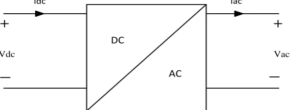
[image:21.595.178.479.239.717.2]The DC to AC converters more often known as inverters, depending on the kind of the source of feeding and the related topology of the power circuit, are classified as voltage source inverters (VSI) and current source inverters (CSI). The following Figure 2.8 shows the types of inverter.
Idc Iac
Vdc Vac
DC
[image:21.595.181.467.242.350.2] [image:21.595.179.476.404.528.2] [image:21.595.167.487.586.705.2]AC
Figure 2.8 :( a) General block diagram Idc
Iac
Vdc Load Voltage
C DC LINK
DC
AC
Figure 2.8 :( b) Voltage Source Inverter (VSI) Idc
I LOAD
Vdc Load Current
I DC L
DC
AC
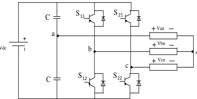
Three phase counterparts of the single phase half and full bridge voltage source inverters are shown in Figures 2.9 and 2.10. Single phase (VSI) cover low range power applications and three phase (VSI) cover medium to high power applications. The main purpose of these topologies is to provide a three phase voltage source, where the amplitude, phase and frequency of the voltages can be controlled. The three phase DC-AC voltage source inverters are extensively being used in motor drives, active filters and unified power flow controllers in power systems and uninterrupted power supplies to generate controllable frequency and AC voltage magnitudes using various pulse width modulation (PWM) strategies. The standard three phase inverter shown in Figure 2.10 has six switches the switching of which depends on the modulation scheme. The input DC is usually obtained from a single phase or three phase utility power supply through a diode bridge rectifier and LC or C filter [2]. There are many applications required DC-AC conversion especially in industrial. In example, motor control and renewable energy where the DC source will be inverted to AC output to suit the motor rating. The speed of the AC motor can be controlled by controlling the output voltage frequency and amplitude. Vdc Vcn Vbn Van n
S 12
S S
[image:22.595.154.483.494.659.2]S 11 21 22 C C a b c
Vdc
Vcn Vbn Van
n
S 22
S S
[image:23.595.159.477.73.235.2]S 21 31 32 S S 12 11 a b c
Figure 2.10: Three phase full bridge inverter
The load is fed form a voltage source inverter with current control. The control is performed by regulating the flow of current to load. Current controllers are used to generate gate signals for the inverter. Proper selection of the inverter devices and selection of the control technique will guarantee the efficacy of the drive. Voltage source inverters (VSI) are devices that convert a DC voltage to AC voltage of variable frequency and magnitude. They are very commonly used in adjustable speed drives and are characterized by a well-defined switched voltage wave form in the terminals [15]. Figure 2.8(b) shows a voltage source inverter. The AC voltage frequency can be variable or constant depending on the application.
Vdc
S 22
S S
S
21 31
32
S S
12 11
a
b
[image:24.595.218.444.69.239.2]c
Figure 2.11: Voltage Source Inverter
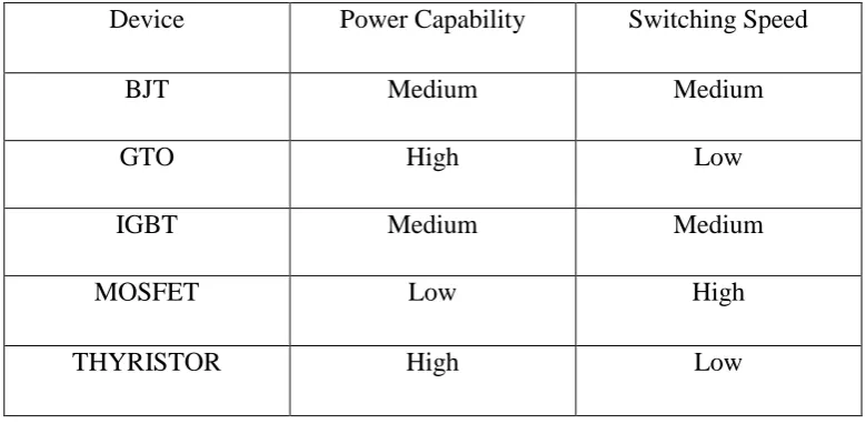
While MOSFET is considered a universal power device for low power and low voltage applications, IGBT has wide acceptance for motor drives and other application in the low and medium power range. The power devices when used in motor drives applications require an inductive motor current path provided by antiparallel diodes when the switch is turned off [20].
Table 2.1: Devices Power and Switching Capabilities
Device Power Capability Switching Speed
BJT Medium Medium
GTO High Low
IGBT Medium Medium
MOSFET Low High
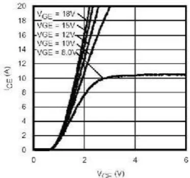
[image:24.595.124.514.467.658.2]2.4.2 IGBTs
IGBTs provide high input impedance and are used for high voltage applications. The high input impedance allows the device to switch with a small amount of energy and for high voltage applications the device must have large blocking voltage ratings. The device behavior is described by parameters like voltage drop or on resistance, turn on time and turn off time. Figure 2.13 shows the characteristic plot of the device. Inverter with IGBTs is shown in Figure 2.12.
Vdc
S 22
S S
S
21 31
32
S S
12 11
a
b
[image:25.595.202.430.300.464.2]c
Figure 2.12: Inverter with IGBTs and Antiparallel Diodes
[image:25.595.223.410.551.726.2]REFERENCES
[1] Zhong, Qing-Chang, and George Weiss. "Synchronverters: Inverters that
mimic synchronous generators." Industrial Electronics, IEEE Transactions on 58.4 (2011).
[2] Salam, Zainal, Abdul Aziz, and Mohd Junaidi. "The Design and
Development of a High Performance Bi-directional Inverter for Photovoltaic Application." (2003).
[3] " FPGA based Fuzzy Logic Control for Single Phase Multilevel Inverter.” international Journal of Computer Applications (0975 – 8887), Volume 9 No.3, November, 2010.
[4] Zhong, Jinghua. "PID controller tuning: a short tutorial." Mechanical Engineering, Purdue, University (2006).
[5] Bakshi, MV Bakshi UA.” Dc Machines and Synchronous Machines”.
Technical Publications, 2007.
[6] J. J. Grainger and W. D. Stevenson, Power System Analysis. NewYork:McGraw-hill,1994.
[7] D. P. Kothari and I. J. Nagrath, Electric Machines, 3rd. New Delhi, India:McGraw-Hill, 2004.
[8] Zhong, Qing-Chang, and Tomas Hornik. Control of Power Inverters in Renewable Energy and Smart Grid Integration. Wiley-IEEE Press, 2012.
[9] Chan, Tze-Fun. "Synchronous Machines." Encyclopedia of Life Support Systems (EOLSS), Eolss Publishers, Oxford UK (2003).
[10] Karuppanan, P., and K. Mahapatra. "PLL with PI, PID and Fuzzy Logic Controllers based Shunt Active Power Line Conditioners." Power Electronics, Drives and Energy Systems (PEDES) & 2010 Power India, 2010 Joint International Conference on. IEEE, 2010.
converter of PV module." Electric Machines & Drives Conference (IEMDC), 2011 IEEE International. IEEE, 2011.
[12] Cecati, Carlo, Fabrizio Ciancetta, and Pierluigi Siano. "A multilevel inverter for photovoltaic systems with fuzzy logic control." Industrial Electronics, IEEE Transactions on 57.12 (2010).
[13] Chan, Tze-Fun, Pieter Borsje, and Weimin Wang. "Application of Unscented Kalman filter to sensorless permanent-magnet synchronous motor drive."Electric Machines and Drives Conference, 2009. IEMDC'09. IEEE International. IEEE, 2009.
[14] Ma, Zhenyu, Qing-Chang Zhong, and Joseph D. Yan. "Synchronverter-based Control Strategies for Three-phase PWM Rectifiers."IEEE2012.
[15] B. K. Bose, Power Electronics and Variable Frequency Drives, 1 ed: Wiley, John &Sons, 1996.
[16] Jadric, Ivan, Dusan Borojevic, and Martin Jadric. "Modeling and control of a synchronous generator with an active DC load." Power Electronics, IEEE Transactions on 15.2 (2000): 303-311.
[17] Prabha Kundur, “Power System Stability and Control”, 2007
[18] Zhong, Qing-Chang, and Tomas Hornik. "Synchronverters: Grid Friendly Inverters That Mimic Synchronous Generators." Control of Power Inverters in Renewable Energy and Smart Grid Integration (2013).
[19] Zhong, Qing-Chang. "Four-quadrant operation of AC machines powered by inverters that mimic synchronous generators." Power Electronics, Machines and Drives (PEMD 2010), 5th IET International Conference on. IET, 2010.
[20] Arroyo, Enrique L. Carrillo. Modeling and simulation of permanent magnet synchronous motor drive system. Diss. UNIVERSITY OF PUERTO RICO, 2006.
[21] Younis, M. A. A., N. A. Rahim, and S. Mekhilef. "Harmonic reduction in three-phase parallel connected inverter." World Academy of Science, Engineering and Technology 38 (2009)
[22] NEAMŢU, Ovidiu. "Three-Phase Inverter with Two Bridges Optimized on Simulations."
[23] T. Sebastian, G. Slemon, and M. Rahman, "Modelling of permanent magnet