International Journal of Emerging Technology and Advanced Engineering
Website: www.ijetae.com (ISSN 2250-2459,ISO 9001:2008 Certified Journal, Volume 5, Issue 3, March 2015)
24
No Load Performance of a Novel Synchronous Permanent
Magnet Generator with Soft Magnetic Composite
Hani Fekri
1, S. Mahmoud HashemiNejad
2 1Dept. of Electrical Engr., Azad University, Bam Branch, Iran
2PhD, Dept. of Energy, Material & Energy Research Center, Karaj, Iran
Abstract— This paper introduces a new axial field flux synchronous permanent magnet generator for small wind turbine applications. 3D finite element analysis used to investigate, design and optimize a 3-phase 12/10-pole machine analysis used to investigation the back-EMF, open circuit flux linkage, winding inductance, cogging torque etc. After construction of the designed proposed machine the practical results compared with the simulation results. A good compliance between these two criteria were observed. Soft magnetic composite (SMC) material are introducing a new window to construction of both cores and rotors of the electrical machinery. This structure in conjunction with SMC facilitates design and construction and well fitted to the fast prototyping and economic manufacturing, compatible with growing need to reduce both cost and environmental impacts.
Keywords— Axial field (AF), renewable energy, flux switching (FS) finite element method (FEM), permanent magnet synchronous generator (PMSG).
I. INTRODUCTION
Wind is one of the most available clean energies in the world. Wind energy is originated by the power of sun but, even when the sun on the night or cloudy days is not available, one may use its energy indirectly via a wind energy capturing system. If in a region you have dominant wind then you may use this clean energy. Small wind turbine is a very good candidate for promoting the usage of renewable energies among the communities. In the other hand generating & consuming energy locally is one of the best ways to reduce the power transmissions loss and to make environmental improvements. One of the main parts of the wind turbines is a generator. Traditional laminated cores have been improved in recent years and soft magnetic composite (SMC) is among the tools for this progress. It facilitates faster construction period, less loss of materials in cheaper prices. [1-6] This kind of generators are not only suitable for wind energy applications but also are being proposed for new applications such as hybrid electric vehicles.[7] Widely Soft magnetic composite (SMC) materials are especially suitable for developing electrical machines with three-dimensional (3-D) magnetic flux path.[8]
II. METHODS AND ANALYSIS
Direct drive generator (DDG) are gaining more and more attention. Due to gearless functioning they reduce the maintenance and operational costs. [9] Generators with permanent magnet excitation have special place among DDGs. Caricchi and coauthors proposed a simple disk shape stator without any slot, and put permanent magnets on the stator disk directly. Although this structure is easy to construct, but due to the created comparatively large air gaps reduced the efficiency of the generator. [10] In this research we constructed our recently proposed novel axial flux synchronous permanent magnet (AFSPM) generator. [11] This machine has single stator and double rotors. Finally, after several different structure which tried, we reached to this present design for a simpler stator segments which are both easy to take from the mold and avoiding any complicated mold for pressing the SMC powder. Permanent magnets or located between the stator segments which is depicted in the Figure 1. The windings are placed on the middle, part of the drawing, or on the stator.
Unlike the other types of this category, construction of this generator is straightforward and simple due to slotless stator segments. Among Permanent Magnet (PM) generators, axial flux machines have high power density and excellent efficiency. [12] In fact the first electrical machine which was built in 1831 by Faraday had AFPM structure and yet it is among the best introduced structure for variety of applications. [13]
International Journal of Emerging Technology and Advanced Engineering
Website: www.ijetae.com (ISSN 2250-2459,ISO 9001:2008 Certified Journal, Volume 5, Issue 3, March 2015)
[image:2.612.75.270.148.329.2]25
Figure 1 – 3-D view of the proposed axial flux PM generatorThe periodical variation of flux linkage which is in harmony with rotor position will induce sinusoidal back-EMF in the coils.
Figure 2 – Main flux passage routes (a) between down side rotor segment and stator (b) between upper side rotor segment and stator.
There are many methods introduced to choose the ratio of the number of stator segments and rotor poles in PM machines [14-16], we used one of the most accepted combinations of 12/10 AFFSPMG based on [17] which is shown in Equation (1).
{
(1)
Where , and m is stator pole number, rotor pole number and phase number respectively.
In this way we could get a better result firstly for the no load output voltages and consequently for the cogging torques and output power. The flux switching occurs times per each cycle therefore we may write it in Equation (2):
(2)
III. FINITE ELEMENT ANALYSIS
Finite element (FE) is an accepted numerical method which properly linked to computer science and engineering. In the electromagnetic problems, FE analysis consist of discretization and solving of complicate and nonlinear Maxwell‘s equations in the both 2D and 3D dimension spaces. The important equation that uses in this method is shown as (3). [18]
𝛻 (
𝛻
⃑⃑ )
(3)
Where A is potential vector, Js is current density and µ is
permeability of the medium and is the conductivity. Other quantities such as flux (Equation 7) density, torque, voltage (Equation 8) …etc. can be calculated by this quantity:
∬ ∮ (
)
(7)
(8)
The inputs data for 3D finite element analysis for the stator, which was used in simulation of this structure are given in table I.
The outputs shows proper result for wind energy applications. Figure 3 shows flux distribution of no load voltage in the stator segment. In the Figure 4 distribution of the flux and its passage from the stator segments to rotor segment is depicted. Simulation shows the critical regions that may cause saturation in the SMC material.
(a)
[image:2.612.70.262.390.533.2]International Journal of Emerging Technology and Advanced Engineering
Website: www.ijetae.com (ISSN 2250-2459,ISO 9001:2008 Certified Journal, Volume 5, Issue 3, March 2015)
26
TABLEISPECIFICATION AND DIMENSIONS OF PROPOSED GENERATOR
Item Designparameter Value
1 Outer diameter 180mm
2 Inner diameter 100mm
3 Stator numer of segments 12
4 Number of rotor poles (each side) 10
5 Rated speed 300rpm
6 Width of stator Back iron 20mm
7 Width of rotor pole 10mm
8 Rotor pole arc 26°
9 Number of turns per coil 100 turn 10 Permanent magnet dimension 40×10×10mm
11 Remanence 1.2T
12 Magnetic coercivity 890000 A/m
The outputs shows proper result for wind energy applications. Figure 3 shows flux distribution of no load voltage in a stator segment. In the Figure 4 distribution of the flux and its passage from the stator segments to rotor segment is depicted. Simulation shows the critical regions that may cause saturation in the SMC material.
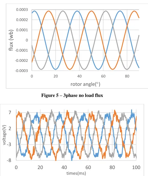
Figure 5 and 6 shows the 3 phase results of no load flux and voltage for three phase windings respectively.
Figure 3 – Magnetic flux distribution through the stator segments
[image:3.612.324.570.303.595.2][image:3.612.50.276.452.608.2]
Figure 4 – Flux distribution and passage from the stator segments (down side) to rotor segment (upper side)
Figure 5 – 3phase no load flux
Figure 6– simulated 3phase no load voltage
-0.0003 -0.0002 -0.0001 0 0.0001 0.0002 0.0003
0 20 40 60 80
flu
x
(w
b
)
rotor angle()
-8 -3 2 7
0 20 40 60 80 100
vo
lt
ag
e(
V)
International Journal of Emerging Technology and Advanced Engineering
Website: www.ijetae.com (ISSN 2250-2459,ISO 9001:2008 Certified Journal, Volume 5, Issue 3, March 2015)
27
IV. CONSTRUCTION OF THE GENERATOR
Making a core with traditional laminated steel sheets and/or similar soft composite material segments needs extensive efforts such as providing several complicated molds which each of them takes lots of time to design and construct. This project took three years of time, in the initial two years, we tried a preliminary design for stator core with slots for windings. In that stage, it took lots of time and budget to make the needed mold. Then taking out the finished pressed composite powder from the mold was very difficult, and most of the time we were witnessing some cracks around the slots of the place for winding, in the stator segments.
[image:4.612.327.560.128.310.2]This made us to find a simpler structure both for mold making and taking out from the mold. In the Figure 7 twelve proposed stator segments of the generator is shown. It is placed in the middle of the figure. Also twenty segments of the side rotors which will be placed in the left and right of stator is shown, before it‘s assembling. For better recognition, there is no permanent magnet and winding in this figure.
Figure 7 – Stator pieces in the middle two rotors in the sides of the stator.
[image:4.612.49.288.386.565.2]In the Figure 8 the finished stator is indicated. Between the segments of the stator permanent magnets are placed. The winding is not seen as they are placed in the simple slots, in the both ends of the stator segments. The whole stator is fixed by special resin and at the most outer bound a circular aluminum yoke is designed and constructed to held stator set.
Figure 8– Stator of the generator which is fixed in a special resin
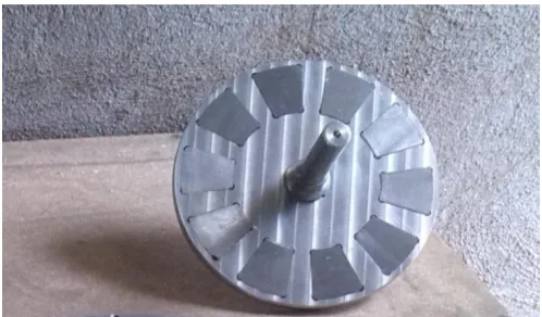
In the Figure 9 the rotor is indicated. This is one of two rotors which will be placed latter, in the both sides of the stator of the generator. The 10 pieces of the rotor is fixed in the slot of an aluminum made disk. A steel shaft is placed in the center of this aluminum disk for coupling it with driving electric motor as tested prime mover.
Figure 9 – One of two rotors which will be placed in both side of the stator
[image:4.612.323.572.404.550.2]International Journal of Emerging Technology and Advanced Engineering
Website: www.ijetae.com (ISSN 2250-2459,ISO 9001:2008 Certified Journal, Volume 5, Issue 3, March 2015)
[image:5.612.320.570.113.272.2]28
Figure 10 – Experimental setup for the proposed generatorV. EXPERIMENTAL RESULTS
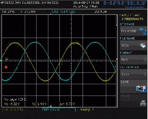
In order to validate the computational result with experimental data, the output of the measurement instruments are extracted (Figure 11) and compared. Figure 12 shows the one phase simulated and actual waveform of no load voltage and harmonic analysis of them is depicted in Figure 13.
[image:5.612.53.288.131.314.2]Figure 11 – two phase of three phase no load voltage
Figure 12 – Actual and simulated no load voltage
Results show good agreement between the outputs of FE analysis and actual measurements.
Figure 13 – Harmonic spectrum of no load voltage
VI. CONCLUSION
A newly 3-phase 12/10-pole AFSPM generator structure is developed. The electromagnetic properties, including the open-circuit flux, the air-gap flux density distribution, the linkage, the EMF, and the winding inductance, etc., are analysed by 3-D finite elements method. A prototype is built to verify the characteristics under open-circuit situation. The simulation and measured results agree with each other very well. The results show both flux linkage and phase EMF are essentially sinusoidal. The synchronous machine can serve as a proper candidate for wind power generator as well as other vehicular applications.
-10 -5 0 5 10
0 20 40 60 80 100
vo
lt
ag
e(
V)
times(ms)
Simulated Actual
0 2 4 6
0 50 100 150 200 250 300 350 400
vo
lt
ag
e(
v)
frequency (Hz)
[image:5.612.323.566.320.452.2] [image:5.612.50.289.430.623.2]International Journal of Emerging Technology and Advanced Engineering
Website: www.ijetae.com (ISSN 2250-2459,ISO 9001:2008 Certified Journal, Volume 5, Issue 3, March 2015)
29
REFERENCES
[1] Cvetkovski, G. ; Petkovska, L. ; Cundev, M. Gair, S. ―Improved design of a novel PM disc motor by using soft magnetic composite material‖; Magnetics Conference, 2002. INTERMAG Europe 2002. IEEE International DOI: 10.1109/INTMAG. 2002. 1001049 Publication Year: 2002
[2] Yicheng Chen; Pillay, P. ―Axial
flux PM wind generator with soft magnetic composite core ‖ Industry Applications Conference, 2005. Fourtieth IAS Annual Meeting. Conference Record of the 2005 Volume: 1 Publication Year: 2005 , Page(s): 231 - 237 Vol. 1 [3] Khan, M.A.; Pillay, Batane, N.R.; Morrison, D.J.P.
"Prototyping a Composite SMC/Steel Axial-flux PM Wind
Generator‖ ; Industry Applications Conference, 2006. 41st IAS
Annual Meeting. Conference Record of the 2006 IEEE Volume: 5 Publication Year: 2006 , Page(s): 2374 - 2381
[4] Ahmed Chebak, Philippe Viarouge, Jérôme Cros,"Optimal design of a high-speed slotless permanent magnet synchronous generator with soft magnetic composite stator yoke and rectifier load‖, Mathematics and Computers in Simulation,2010,pp 1-13
[5] Youguang Guo ; Jianguo Zhu ; Haiyan Lu ; Zhiwei Lin ; Yongjian Li "Core Loss Calculation for Soft Magnetic Composite Electrical Machines‖ Magnetics, IEEE Transactions on Volume: 48 , Issue: 11 DOI: 10.1109/TMAG.2012.2197677 Publication Year: 2012 , Page(s): 3112 - 3115
[6] Kolano, R. ; Kolano-Burian, A. ; Polak, M. ; Szynowski, J. "Application of Rapidly Quenched Soft Magnetic Materials in Energy-Saving Electric Equipment Magnetics‖, IEEE Transactions
on Volume: 50 , Issue: 4 , Part: 1
DOI: 10.1109/TMAG.2013.2283918 Publication Year: 2014 , Page(s): 1 – 4
[7] Maloberti, O. ; Figueredo, R. ; Marchand, C. ; Choua, Y. ; Condamin, D. ; Kobylanski, L. ; Bomme, E. "3-D–2-D Dynamic Magnetic Modeling of an Axial Flux Permanent Magnet Motor With Soft Magnetic Composites for Hybrid Electric Vehicles‖ Magnetics, IEEE Transactions on Volume: 50, Issue: 6 , Part: 2 DOI:10.1109/TMAG. 2014.2300152 Publication Year: 2014, Article#: 8201511
[8] Youguang Guo ; Jianguo Zhu ; Haiyan Lu ; Zhiwei Lin, Yongjian Li, ―Core Loss Calculation for Soft Magnetic Composite Electrical Machines‖; Magnetics, IEEE Transactions on Volume: 48, Issue:11 DOI: 10.1109/TMAG. 2012.2197677 Publication Year: 2012 , Page(s): 3112 – 3115
[9] Polinder, H. ; Ferreira, J.A. ; Jensen, B.B. ; Abrahamsen,
A.B. ; Atallah, K. ;McMahon, R.A.
"Trends in Wind Turbine Generator Systems‖ Emerging and Selected Topics in Power Electronics, IEEE Journal of Volume:1, Issue: 3 DOI: 10.1109/JESTPE.2013. 2280428 Publication Year: 2013 ,Page(s): 174 - 185
[10] Caricchi, F. ; Maradei, F. ; De Donato, G. ; Capponi, F.G. "Axial-Flux Permanent-Magnet Generator for Induction Heating Gensets‖ Industrial Electronics, IEEE Transactions on Volume:57, Issue:1 DOI:10.1109/TIE.2009. 2028292 Publication Year: 2010 , Page(s): 128 - 137
[11] S. M. HashemiNejad, Hani Fekri ‗Switching Permanent Magnet Generator for Small Wind Turbine‘ International Journal of Inventive Engineering & Sciences (IJIES), ISSN: 2319-9598 (Online), Volume-2 Issue-10, Page No.: 5-8, September 2014. [12] Axial-Flux PM Machines With Variable Air Gap Vansompel,
H. ; Sergeant, P. ; Dupre, L. ; van den Bossche, A. Industrial Electronics, IEEE Transactions on Volume: 61 , Issue: 2 DOI: 10.1109/TIE.2013.2253068 Publication Year: 2014 , Page(s): 730 - 737
[13] A Comprehensive Review of Axial-Flux Permanent-Magnet Machines Kahourzade, S. ; Mahmoudi, A. ; Hew Wooi Ping ; Uddin, M.N. Electrical and Computer Engineering, Canadian Journal
of Volume: 37 , Issue: 1
DOI: 10.1109/CJECE.2014.2309322 Publication Year: 2014 , Page(s): 19 – 33
[14] Z. Q. Zhu, J. T. Chen, ‖Advanced Flux-Switching Permanent Magnet Brushless Machines‖, IEEE Trans on magnetics, vol 46, no 6, pp 1447-1453, June 2010
[15] Emmanuel Hoang, Abdel Hamid Ben Ahmed, Jean Lucidarme, ‖Switching flux permanent magnet polyphased synchronous machines ‖,In Proceeding. Of 7th European .Conference of. Power Electron. Application. 1997, vol. 3, pp. 903–908.
[16] Jianzhong Zhang, Ming Cheng, Zhe Chen, ―Optimal design of stator interior permanent magnet machine with minimized cogging torque for wind power application‖, Journal of Energy Conversion and Management.49,(2008), pp 2100–2105
[17] Jianzhong Zhang, Ming Cheng, Zhe Chen ―A Novel Stator Interior Permanent Magnet Generator for Direct-Drive Wind Turbines‖, Proceeding of International Conference on Electrical Machines and Systems,2007, pp723-728
[18] Ahmed Chebak, Philippe Viarouge, Jérôme Cros,"Optimal design of a high-speed slotless permanent magnet synchronous generator with soft magnetic composite stator yoke and rectifier load", Mathematics and Computers in Simulation, 2010,pp 1-13
Acknowledgement