International Journal of Emerging Technology and Advanced Engineering
Website: www.ijetae.com (ISSN 2250-2459,ISO 9001:2008 Certified Journal, Volume 4, Issue 10, October 2014)
16
Data Throughput Maximization Using Adaptive Modulation for
Single Carrier Base Band Transmission System
Mohammed B. Shukur
1, Younis M. Abbosh
21Communication Engineering Department/College of Electronics Engineering/University of Mosul/Mosul/Iraq
2Computer Engineering Department/College of Electronics Engineering/University of Mosul/Mosul/Iraq
Abstract—This paper examines the benefits of using
adaptive modulation in terms of spectral efficiency and probability of bit error in single carrier baseband systems. Specifically, the performance enhancement has been examined using channel quality indicator in conjunction with adaptive modulation. The paper investigates the output (best modulation scheme) on basis of channel quality indicators (SNR, Doppler shift, and BER) of different modulation types (BPSK, QPSK, and M-QAM) from the point of view of higher data rates. The channel used here is the Rayleigh fading channel corrupted by AWGN. The findings regarding the advantages of using predictive measures to foresee the state of the channel is used for the adjustments to transmissions accordingly. This work gives an idea when channel prediction is most valuable to adaptive modulation and when it is weak. Matlab program has been used to implement the whole system.
Keywords—Adaptive Modulation, Bit Error Rate (BER), Signal to Noise Ratio (SNR), Digital Modulation Schemes, Equalization and channel estimation, Rayleigh Fading Channel, Doppler Effect and Additive White Gaussian Noise (AWGN).
I. INTRODUCTION
The need for communication with high data rate and accepted bit error rate (BER) led to look for and investigate new techniques of digital communication, and to use the available bandwidth in efficient ways. The spectrum efficiency can be increased by using a good channel estimator with high order modulation schemes [1].
Adaptive modulation scheme which depends on link quality indicator (LQI) reports can be used to maximize the data throughput [2]. The modulation scheme of the adaptive modulator is chosen to achieve a maximum data throughput with accepted BER. The modulation scheme of the adaptive modulator is chosen according to the channel state.
The high order modulation schemes are used with good conditions of the channel. The lower order modulation schemes (BPSK, QPSK) are used with bad conditions of the channel [3].
The multipath fading channel can be expressed as a Rayleigh fading channel if there is no line of sight between the transmitter and the receiver [4]. The Rayleigh fading channel distorts the amplitude and the phase of the modulated signal. A high accuracy channel estimator is needed to overcome the rapid fading introduced by Rayleigh fading channel [1]. Even a good channel estimator is used, the BER performance will degrade due to rapid fading [2].
The relative movement between the transmitter and the receiver introduces another channel effect known as Doppler effects [4]. Doppler effects introduce a shift in the received signal frequency. Also Doppler effects lead to time varying channel (time selectivity channel). The coherence time is inversely proportional to the Doppler shift frequency. The coherence time is the time over which the channel is still can be considered constant.
The channel estimation can be done by inserting defined symbols at known instants of time. The inserted symbols are known as pilots. The pilots should be inserted periodically. The time period of the pilot should be smaller than the coherence time in order to track the channel variation. If the pilot time period is greater than the coherence time then the estimator cannot track the channel variation. James K. Cavers proposed a pilot symbol assisted modulation (PSAM). The channel effect on the amplitude and phase of the modulated symbols can be found by using PSAM. If there is no more one path between the transmitter and receiver then the channel effect on the received signal can be removed by multiplying the received signal by the inverse of estimated channel effect parameters; therefore the original transmitted pulse shape will be recovered keeping the peak to average ratio as it was [5].
International Journal of Emerging Technology and Advanced Engineering
Website: www.ijetae.com (ISSN 2250-2459,ISO 9001:2008 Certified Journal, Volume 4, Issue 10, October 2014)
17
In this work different digital modulation techniques are experienced to find the optimum modulation scheme for the instantaneous Rayleigh fading channel. Also, the effect of non-ideal channel estimation and Doppler shift are taken into account.
II. SINGLE CARRIER WIRELESS COMMUNICATION SYSTEM
2.1 Additive White Gaussian Noise (AWGN)
The received signal of any communication system is affected by AWGN in additive way. The AWGN consists of a large number of random independent components. The power spectral density (PDF) of the AWGN is constant [6].
( ) ( ) ( )
(1)
Where ( ) is the transmitted signal, ( ) is the noise, and ( ) is the received signal.
2.2 Multipath Fading Channel
In any wireless communication system, the receiver receives multiple copies of the transmitted signal with different time delays. The signal copies are created from the original transmitted signal due to reflection, refraction, scattering and deflection. The time delays between the signal copies appear as constructive or destructive interference at the receiver. The constructive or destructive interference are known as multipath fading effect. The multipath fading results in inter symbol interference (ISI). Equation (2) represents the effect of the multipath on the received signal strength [4].
( ) ( ) ( ) ( ) (2) Where ( ) are the complex channel coefficients.
[image:2.612.53.287.484.605.2]Transmitter X(t) Channel X(t)ӿh(t,T) Receiver X(t)ӿh(t,T)+n(t) AWGN N(t)
+
Figure 1 System model for transmitting information through a channel with additive white Gaussian noise [4].
2.3 Rayleigh Fading Channel
In Rayleigh fading channel, there are large number of signal copies at the receiver and there is no line of sight between the transmitter and the receiver. This kind of channel called Rayleigh fading channel because “the envelope of such received signal is statically described by Rayleigh probability density function PDF”. The following equation represents the Rayleigh PDF [7].
( ) { [ ]
(3)
Where is the prediction mean power of the multipath signal.
2.4 Fast Fading versus Slow Fading Viewed In the Time Domain
The channel can be characterized as fast fading channel if , (where is the channel coherence time, and is the time duration of the transmitted symbol). If then the channel can be characterized as slow fading channel. The fast fading channel has low autocorrelation values, so that the channel characteristics change several times during the time duration of the transmitted symbol. Whereas, the slow fading channel has high autocorrelation values and the channel characteristics remain approximately constant during the symbol duration. ”The primary degradation in a slow fading channel, as compared with fast fading, is loss in SNR” [7].
2.5 Maximum Doppler Frequency Shift (Jakes model)
The relative movement between a transmitter and receiver leads to a frequency shift in the received signal. The received signal frequency shift is known as Doppler shift. The Doppler shift for moving receiver and stationary transmitter can be calculated as shown in the following equation [6]
| ⃗ |
( ) (4) Where is the receiver velocity, is the speed of light, is the carrier frequency of the signal and is the angle between directions of the receiver velocity and the arriving signal. Equation (4) shows that when the receiver moves toward the transmitter, a maximum positive Doppler shift occurs. And when the receiver moves away from the transmitter then a maximum negative Doppler shift occurs [6].
Doppler spectrum gives a full understand about how fast the channel characteristics are changing with respect to time. The Doppler spectrum ( ) is found by taking the Fourier transform of the channel time correlation function ( ). Therefore, Doppler spectrum is completely associated with the channel characteristics that are varying with respect to time. The following equation shows the normalized ( )[7]
International Journal of Emerging Technology and Advanced Engineering
Website: www.ijetae.com (ISSN 2250-2459,ISO 9001:2008 Certified Journal, Volume 4, Issue 10, October 2014)
18
Where, ( ) is the zero order Bessel function of the first kind, is distance traversed, and is the free space phase constant. Taking the Fourier transform of the above equation, a Doppler spectrum (Doppler PDF) is found. Doppler PDF is plotted as a function of Doppler frequency shift [7].
( )
√ (
)
(6)
[image:3.612.68.271.298.382.2]The Doppler spectrum of the above equation is also called Jakes spectrum. Figure 2 shows the duality relation between multipath intensity profile (time varying channel) and Doppler power spectrum [7-p969].
Figure 2. Relationship between the channel correlation and power density function [7].
Due to multipath effect, the transmitted signal travels over multiple paths to reach the receiver with different times and different angles. Each arriving signal is affected by a different Doppler shift subjected statically to the Jakes model [7]. The Doppler spread ( ) is inversely proportional to the coherence time as shown in equation (7)
(7)
2.6 BER performance for M-array quadrature amplitude modulation (M-QAM)
The data throughput for any communication system can be increased by increasing the bandwidth used to transmit data. Normally in wireless communication system the bandwidth is specified by a national and local license. Due to this specification of the bandwidth a new technologies appear to increase the data throughput without increasing the bandwidth. One of these technologies is to use high order modulation schemes. The high order modulation schemes use the available bandwidth in an efficient way [8].
Gray code constellation [9] is used to perform the square QAM modulation schemes. Cho and Yoon have driven in [2] an expression to show the BER performance of M-array QAM modulation schemes through AWGN channel with respect to SNR as shown in equations (8), (9) and 10.
( ) ∑ ( )
√
( )
( )
√ ∑ { ( ) ((
( )√
)√
( ))} ( )
Where
( ) ( )*
√ + (
*
√ +) ( )
Where ⁄ denotes the signal-to-noise ratio (SNR) per bit.
2.7 BER performance for M-array quadrature amplitude modulation (M-QAM) through Rayleigh fading channel
For M-array QAM modulation schemes passing through a flat fading Rayleigh channel, Waslon T. A. Lopes, WambertoJ.L.Queiroz, Francisco Madeiro and Marcelo S. Alencar have driven an expression to find the BER performance through Rayleigh fading channel as shown in equations (11) and (12) respectively [8].
( ) ∑ ( )
√
( )
( ) √ ∑( { ( ) (
)√
√ ( ) ( )
√ ( ) ( ) )} ( )
2.8 Link adaptation: power and rate control
International Journal of Emerging Technology and Advanced Engineering
Website: www.ijetae.com (ISSN 2250-2459,ISO 9001:2008 Certified Journal, Volume 4, Issue 10, October 2014)
19
In poor channel conditions the power controller transmits a high power and vice versa. The constant SNR at the receiver leads to a nearly constant BER which is needed in many communication systems. Figure (3.a) shows a power control signal. However, in many wireless communication systems there is no need to constant data rate at the receiver. The data throughput of such systems is set to be maximum without increasing the transmission bandwidth. To achieve a high data throughput with accepted BER a data rate controller at the transmitter is needed. The data rate controller is used to control the data throughput according to the channel conditions state. For a good channel conditions a high order modulation schemes are used to achieve a high data throughput and high spectral efficiency. For a poor channel conditions a low order modulation schemes are used to achieve an accepted BER and to maintain the link between the transmitter and the receiver. Figure (3.b) shows a rate control signal [10].
Figure 3. (a) Power control (b) rate control [10].
2.9 Equalization and channel estimation
Due to multipath effects of mobile digital communication systems the problem of the ISI arises. ISI causes a broadening in the received pulse shape with respect to time. This broadening in pulse shape makes the pulse interferes with the adjacent pulses and distorts them. As the data rate increases the ISI also increases and causes a higher BER at the receiver. So ISI is the main problem that prevents the wireless communication system to transmit data with high rates.
The effects of ISI can be minimized at the receiver by using equalizer. For time varying channel an adaptive equalizer is needed to track the channel characteristics variation and to ensure a high transmitting data rate with accepted BER. If ( ) is the original information signal and
( ) is the combined complex baseband impulse response of the channel then the signal received by the equalizer is [11].
( ) ( ) ( ) ( ) (13) Where ( ) is the complex conjugate of ( ), ( ) is the baseband noise at the input of the equalizer, and denotes the convolution operator. If the impulse response of the equalizer is ( ), then the output of the equalizer is [11]
̂( ) ( ) ( ) ( ) ( ) ( ) ( ) ( ) ( ) (14)
The aim of the equalizer is to get
( ) ( ) (15) Where ( ) and F( ) are the Fourier transforms of ( ) and ( ), respectively.
Modulator Tramsmitter Radio Channel
Σ
Equalizer heq(t)
IF Stage Detector Matched Filter IF Receiver Front End Decision Maker +
f(t)=combined impulse response of transmitter, multipath radio channel, and receiver RF/IF
Original Baseband
Message X(t)
Equivalent Noise nb(t)
Equalizer Prediction Error
[image:4.612.54.281.348.570.2]Reconstructed Message Data d(t) f(t) y(t) e(t) - + ^
Figure 4. Block diagram of a simplified communication system using an adaptive equalizer at the receiver [11].
A flat fading channel can be characterized as multipath channel which has only one path and represented as a single tab filter. Therefore, the convolution operation between the signal and channel can be converted into multiplication as shown in equation (16)
[image:4.612.327.554.389.576.2]International Journal of Emerging Technology and Advanced Engineering
Website: www.ijetae.com (ISSN 2250-2459,ISO 9001:2008 Certified Journal, Volume 4, Issue 10, October 2014)
20
III. PRACTICAL WORK PROCEDURE
For a single carrier base band transmission system, totally 107 random bits have been generated by using MATLAB function. The generated bits have been divided into 100 frames each frame contains 105 bits. Six modulation types (BPSK, QPSK, 16QAM, 32QAM, 64QAM and 128QAM) have been used to modulate the randomly generated bits. All the calculated bit error rates are in physical layer and without any error correction. The modulated symbol duration was chosen to be (66.7µsec) so that the symbol bandwidth is much less than the coherence bandwidth. The carrier frequency is set to 2.6GHz and the maximum allowable speed of receiver equipment is 160 Km/h so the maximum Doppler shift frequency becomes 385Hz. The generated symbols have been transmitted through Additive Wide Gaussian Noise (AWGN) channel as well as through Rayleigh flat fading channel with the effect of Additive Wide Gaussian Noise. Each symbol has been transmitted separately through these two channels. At the receiver, an ideal channel estimation has been done to find the Rayleigh fading channel parameters. The ideal Rayleigh fading channel parameters have been used with a single tab equalizer (zero forcing equalizer) to compensate for the effect of Rayleigh fading channel on the received symbol. After that the received symbols were demodulated by a proper demodulation scheme which matches the modulation scheme that was used at the transmitter side to get the received bits. From the received signal, the bit error rate performance is calculated.
IV. RESULTS AND DISCUSSIONS
Figure 5 shows the relation between SNR and BER performance for BPSK modulation/demodulation types at different receiver equipment speed.
Figure5: BER curves for BPSK with ideal channel estimation through Rayleigh and AWGN channels.
Figure 5 shows that the bit error rate performance of moving receiver for different speeds is the same as the performance of static receiver that is affected by Rayleigh multipath channel with AWGN but without any effect of the Doppler shift frequency. The effect of the Doppler shift frequency on the received signal has been completely removed since the prefect Rayleigh fading channel parameters are considered in calculating the received signal. The received signal is calculated by multiplying it by the inverse of the perfect Rayleigh fading channel parameters because a flat fading channel is assumed.
International Journal of Emerging Technology and Advanced Engineering
Website: www.ijetae.com (ISSN 2250-2459,ISO 9001:2008 Certified Journal, Volume 4, Issue 10, October 2014)
21
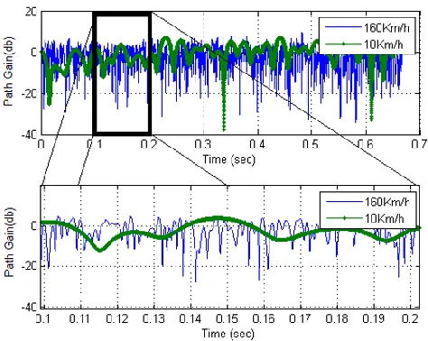
[image:6.612.49.286.219.408.2]The effects of such a speed are expected to be as when the receiver is in a static situation where the signal experiences a flat fading multipath effect. In the second case, the receiver equipment was assumed to be moved in a speed of 160Km/h as a maximum speed of the moving vehicle. Figure 6 shows the effects of the two speeds on the received signal strength.
Figure 6. Actual Rayleigh Fading channel for the two speeds of receiver 10Km/h and 160Km/h.
Figure 6 shows for high moving speed, the received signal has severe fluctuations in the signal power strength (i.e. fast fading) due to effect of the high value of Doppler frequency shift. But for low moving speed of the receiver equipment, the signal has slow fading in the signal power strength.
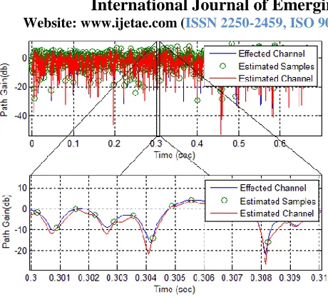
In other case for practical system, Rayleigh fading channel parameters have been estimated by dedicating 10% of the transmitted data as pilot bits. The pilot bits are inserted between the transmitted data. Therefore 10% of Rayleigh faded channel parameters can be estimated at equal time spaced. The remaining 90% of the Rayleigh fading channel parameters are interpolated as shown in figure7.
Figure7: difference between actual channel and estimated channel.
The practical effect of Rayleigh fading channel, samples of estimated Rayleigh fading channel and the estimated Rayleigh fading channel are shown in figure8 and figure9. The two figures are plotted for two different speeds of receiver and they show that for only one transmitted frame. The estimated channels in the two cases are interpolated to functions of 9th degree.
[image:6.612.328.556.433.614.2]International Journal of Emerging Technology and Advanced Engineering
Website: www.ijetae.com (ISSN 2250-2459,ISO 9001:2008 Certified Journal, Volume 4, Issue 10, October 2014)
[image:7.612.51.281.109.317.2]22
[image:7.612.337.551.192.366.2]Figure 9. Channel estimation by using 10% of data as a pilot for 160Km/h receiver speed.
Figure 8 shows that at 10Km/h moving speed of receiver equipment, the actual and the practical estimated Rayleigh fading channels are approximately the same. Figure 9 shows that at 160 Km/h moving speed of receiver equipment there is a difference between the actual and the estimated Rayleigh fading channels which causes a degradation and limitation in BER performance of the received signal as shown in figure10 to figure 15. The difference between the actual and the estimated Rayleigh fading channels at 160Km/h speed is due to high Doppler effect which causes a high fluctuation in the actual Rayleigh fading channel as shown in figure9. In the other word when the receiver equipment speed is 160Km/h, the number of transmitted pilots are not enough to estimate the actual Rayleigh fading channel exactly.
The relationships between signal to noise ratio (SNR) and bit error rate (BER) performance for (BPSK, QPSK,
16QAM, 32QAM 64QAM and 128QAM)
modulation/demodulation types and at different receiver equipment speed have been found. And by using 10% of the transmitted data as pilots to estimate the actual Rayleigh fading channel coefficients. The effect of the Rayleigh fading channel has been nearly removed by considering the estimated Rayleigh fading channel coefficients in the single tab equalizer.
[image:7.612.339.550.397.576.2]Then the output of the equalizer is applied to proper demodulation schemes to recover the transmitting bits with a bit error rate as shown in figure10, figure11, figure12, figure13, figure14 and figure15.
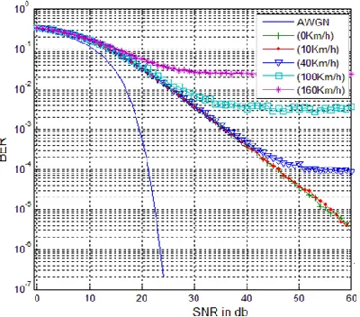
Figure 10. BER curves for BPSK for different speeds, 10% of
transmitted data are used for channel estimation.
International Journal of Emerging Technology and Advanced Engineering
Website: www.ijetae.com (ISSN 2250-2459,ISO 9001:2008 Certified Journal, Volume 4, Issue 10, October 2014)
[image:8.612.59.269.144.347.2]23
[image:8.612.342.546.147.337.2]Figure 12. BER curves for 16QAM for different speeds, 10% of transmitted data are used for channel estimation.
[image:8.612.341.549.376.578.2]Figure 13. BER curves for 32QAM for different speeds, 10% of transmitted data are used for channel estimation.
Figure 14. BER curves for 64QAM for different speeds, 10% of transmitted data are used for channel estimation.
[image:8.612.67.267.394.570.2]International Journal of Emerging Technology and Advanced Engineering
Website: www.ijetae.com (ISSN 2250-2459,ISO 9001:2008 Certified Journal, Volume 4, Issue 10, October 2014)
24
Figure10 to figure15 show that, the worse BER performances of the used modulations have been occurred at the maximum moving receiver speed which is 160Km/s. The BER performance improves as the speed of receiver equipment decreases.
The choice of best modulation scheme for the instantaneous channel conditions, to achieve the desired BER, depends on the values of signal to noise ratio and Doppler frequency shifts (speed of receiver) which are known for the receiver. The following tables show the best modulation scheme used for the instantaneous SNR and receiver speed. As shown from the tables, it is recommended the shadowed values associated with the type of modulation and speed to be considered for a reliable transmission.
Table1.
BER for 0db SNR.
Table2. BER for 10db SNR
Table3. Best BER for 20db SNR
Table4. BER for 30db SNR
Table5. BER for 40db SNR
Table6. BER for 50db SNR
Table 7. BER for 60db SNR
V. CONCLUSIONS
This work identifies the best modulation scheme used with the instantaneous channel conditions (SNR and Doppler effects). Although at any SNR, the BPSK modulation is the best and the 128QAM is the worst in term of BER, but for good channel conditions and low speed of receiver, high order modulation schemes such as 32QAM 64QAM and 128QAM can be used. If the desire BER in physical layer at the receiver is 10^-3, it’s found that for 160Km/h speed of receiver, the BPSK modulation should be used. For 100Km/h, the BPSK and QPSK can be used on condition that the SNR is greater than 30db. For 40Km/h, the 16QAM and 32 QAM can be used on condition that the SNR is greater than 40db. For 10Km/h, the 64 QAM can be used on condition that the SNR is greater than 40 db. And for stationary receiver, the 128 QAM can be used on condition that SNR is around or grater greater than 50db.
REFERENCES
[1] Chang-Joo Kim, Goo-Young Jeong, Han-Kyu Park and Sang-sam Choi, “New Rayleigh Channel Estmator Based On PSAM Channel sounding Technique,” ETRI, Taejeon, Korea, 1997 IEEE, pp. 1518-1520.
[2] Kyongkuk Cho and Dongweon Yoon, “On the General BER Expression of One- and Two-Dimensional Amplitude Modulations,” IEEE Transactions on Communications, vol. 50, no. 7, pp. 1074-1080, july 2002.
[3] Sami H. O. Salih and Mamoun M. A. Suliman1, “Implementation of Adaptive Modulation and Coding Technique using,” International Journal of Scientific & Engineering Research Volume 2, Issue 5, pp.1-4 May-2011.
[4] Oyetunji S. A and Akinninranye A. A, “Performance Evaluation Of Digital Modulation Techniques In Awgn Communication Channel,” International Journal of Engineering Research & Technology (IJERT), Vol. 2 Issue 5, pp. 2100-2106, May-2013
International Journal of Emerging Technology and Advanced Engineering
Website: www.ijetae.com (ISSN 2250-2459,ISO 9001:2008 Certified Journal, Volume 4, Issue 10, October 2014)
25
[6] Evgenii Krouk and Sergei Semenov, “Modulation and CodingTechniqes in Wireless Communication,” John Wiley & Sons Ltd, 2011.
[7] Bernard Sklar, “Digital Communication Fundamentals and Applications,” Second Edition, Prentice Hall, January-2001. [8] Waslon T. A. Lopes, WambertoJ.L.Queiroz, Francisco Madeiro and
Marcelo S. Alencar, “On the General BER Expression of One- and Two-Dimensional Amplitude Modulations,” IEEE Transactions on communication, Vol. 50, No. 7 , pp. 1074-1080,July 2002.
[9] P. J. Lee. “Computation of the Bit Error Rate of Coherent M-ary PSK with Gray Code Bit Mapping”.IEEE Transactions onCommunications, vol. 34, no. 5, pp. 488–491, May 1986. [10] Erik Dahlman, Stefan Parkvall, Johan Sköld and Per Beming, “3G
Evolution: HSPA and LTE for Mobile Broadband,” second edition, Elsevier, Second edition 2008.
![Figure 1 System model for transmitting information through a channel with additive white Gaussian noise [4]](https://thumb-us.123doks.com/thumbv2/123dok_us/8707563.881073/2.612.53.287.484.605/figure-model-transmitting-information-channel-additive-white-gaussian.webp)
![Figure 2. Relationship between the channel correlation and power density function [7]](https://thumb-us.123doks.com/thumbv2/123dok_us/8707563.881073/3.612.68.271.298.382/figure-relationship-channel-correlation-power-density-function.webp)
![Figure 3. (a) Power control (b) rate control [10].](https://thumb-us.123doks.com/thumbv2/123dok_us/8707563.881073/4.612.54.281.348.570/figure-a-power-control-b-rate-control.webp)