International Journal of Emerging Technology and Advanced Engineering
Website: www.ijetae.com (ISSN 2250-2459,ISO 9001:2008 Certified Journal, Volume 5, Issue 7, July 2015)
59
Thermal Analysis and Optimisation of a Ventilated Disk
Brake Rotor using CFD Techniques
Sagar Khivsara
1, Rucha Bapat
2, Nikhil Lele
3, Ameya Choudhari
4, Mahesh Chopade
5 1Department of Mechanical Engineering, Indian Institute of Science, Bangalore, India2Department of Mechanical Engineering, University of Illinois at Chicago, U.S. 3,4,5Department of Mechanical Engineering, MAAER’s MIT College of Engineering, Pune, India Abstract — The aim of this investigation is to achieve
thermal optimisation of a Ventilated Disc Brake Rotor (VDBR) by the use of Computational Fluid Dynamics (CFD) techniques. The analysis of an existing VDBR model is first presented. Literature suggests that the prime cause of failure is overheating and large thermal stress which arises due to ineffective heat transfer. In this paper, we present a comparative study to optimize the heat transfer rate by simple modifications. These simple modifications are considered due to their ease of manufacturing. It was found that a considerable enhancement in the heat transfer rate can be attained when the proposed modifications are incorporated in the design.
Keywords— Computational Fluid Dynamics (CFD), Heat Transfer, Optimization, Ventilated Disc Brake Rotor (VDBR),
I. INTRODUCTION
Conventional high speed vehicles are typically equipped with a Ventilated Disc Brake Rotor (VDBR). As shown in figure 1, a VDBR consists of two discs with multiple radial fluid flow passages (vanes) between the discs. When brakes are applied, hydraulically actuated pistons cause the brake pads to exert a pressure on the outer surface of the discs [1]. The kinetic energy of the vehicle is converted into heat due to friction between the brake pads and disc surfaces. This thermal energy is primarily dissipated by convection through the vanes of the VDBR.
[image:1.612.344.521.246.371.2]Insufficient heat transfer leads to overheating of the rotor and eventual failure. This is more likely in extreme applications like emergency braking or excessive repetitive braking [2]. Analytical modelling of the actual situation is very complex and time consuming [3, 4]. There are a lot of assumptions involved with respect to the fluid flow and heat transfer parameters.
Figure 1: Ventilated Disc Brake Rotor (VDBR) arrangement
Experimental evaluation of a VDBR is very expensive. It yields results which are very accurate and realistic [5], but this approach is not feasible in the development stage. In contrast, computational modelling offers a lucrative alternative for thermal analysis of a VDBR. Powerful computational facilities enable the heavy number crunching required for numerical solutions. For this analysis, commercial software ANSYS has been used.
A suitable discretization strategy is essential for a successful Computational Fluid Dynamics (CFD) analysis. ANSYS ICEM CFD is used as a pre-processor for obtaining an appropriate mesh.
International Journal of Emerging Technology and Advanced Engineering
Website: www.ijetae.com (ISSN 2250-2459,ISO 9001:2008 Certified Journal, Volume 5, Issue 7, July 2015)
60
II. PHYSICS OF THE PROBLEM AND ASSUMPTIONS FORNUMERICAL MODELLING
A VDBR is attached to the wheel hub and rotates with the wheel. Heat generated due to the friction between brake pads and the disc outer surface increases the temperature of the rotor. This heat is then dissipated due to forced convection by air flowing through the vane passages. It can be modelled as a rotating duct system with heat flux applied on the walls.
The pressure distribution of the pad over the disc is not uniform in reality. Factors like pressure distribution, reduction in velocity and duration of brake activation influence the distribution of heat generation and structural stability [8]. Due to these factors, specifying a constant heat flux boundary condition [9] is not appropriate. For this comparative study, we use the constant temperature boundary condition.
The axisymmetric nature of the geometry of the disc allows the modelling of a sector and use of periodic boundary condition in ANSYS Fluent [4].
The total heat transfer rate is obtained by the multiplying the heat transfer rate for one vane with the total number of vanes.
This analysis being of a comparative nature, heat transfer due to natural convection and radiation are neglected [4]. Additionally, the geometry is simplified by excluding the wheel hub in geometry since its influence on heat transfer for different internal geometries within the two discs would be similar. Identical boundary conditions and mesh were employed for comparative studies of different vane parameters.
To obtain the optimum geometric configuration from the point of heat transfer, design parameters are varied in a stepwise manner. For this investigation, the following assumptions are made based on engineering estimates and the surveyed literature:
1.A constant temperature boundary condition was specified instead of a constant/variable flux boundary condition. Although this boundary condition is not very close to the real situation, it gives an accurate estimation of the relative efficacy of different geometries for dissipation of the generated heat and also significantly simplifies the analysis.
2.Since the rotor material and boundary condition remains identical for the cases under comparison, the effect of conduction through the rotor will remain comparable, and hence, is ignored.
3. The contribution of radiation heat transfer has been neglected for comparative study, as the disc temperature distribution is identical due to specification of same boundary conditions for different cases under consideration. Also, the contribution of radiation heat transfer compared to forced convection heat transfer can be expected to be low at high rotational speeds.
4. Steady state equations are solved for constant rotational speed of the rotor. The transients are not modelled in this investigation.
5. A single flow passage with periodic boundary condition is modelled to account the influence of adjacent flow passages.
6. Due to identical wall temperatures, the contribution of natural convection heat transfer will be similar for cases under consideration [4]. Hence, it is not modelled in this analysis.
III. CFDANALYSIS OF EXISTING VDBRMODEL
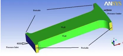
[image:2.612.339.547.479.575.2]A preliminary analysis was performed on the geometry of an existing VDBR model used commonly in commercial vehicles. Actual dimensions of the vane were measured. The rotor consists of 36 vanes for air passage. As already mentioned, the axisymmetric nature of the geometry simplified the model. Only one vane was modelled and meshed for further analysis.
Figure 2 shows the geometry that was used for meshing and the boundary conditions specified in the solver.
Figure 2: 3D geometry with boundary conditions
The blocking technique in ASYS ICEM CFD was utilized for generation of a structured hexahedral mesh. The number of nodes on various edges of the geometry can be easily changed to control the mesh size and distribution.
Hexahedral mesh was chosen as it offers several advantages over a tetrahedral mesh; such as better control over size and skewness of the mesh elements [10, 11].
International Journal of Emerging Technology and Advanced Engineering
Website: www.ijetae.com (ISSN 2250-2459,ISO 9001:2008 Certified Journal, Volume 5, Issue 7, July 2015)
[image:3.612.64.274.135.272.2]61
Figure 3: A typical meshGrey cast iron was used as the material of the rotor and its thermo physical properties were specified.
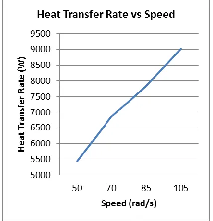
The boundary condition for fluid inlet was specified as a pressure-inlet and the fluid outlet as a pressure-outlet. The wall was assigned a temperature of 900 K. A frame motion [12] of 70 rad/s (which is equivalent to 80 kilometres per hour linear speed) was specified for the rotor mesh. Cases with frame motion speeds of 50 rad/s, 70 rad/s, 85 rad/s and 105 rad/s were analysed.
The results for these simulations were found to be qualitatively in agreement with the experimental observations in the literature. It can be seen in figure 4 that as expected, the heat transfer rate increases with an increase in the rotational speed of the rotor.
Figure 4: Effect of rotor speed on the heat transfer rate
IV. MODIFICATIONS AND TRENDS OBTAINED IN 2D
ANALYSIS
For studying the effects on heat transfer rate, geometric parameters of the rotor were varied and the models were analysed using CFD.
A. Number of vanes
[image:3.612.373.514.296.399.2]Keeping the diameter of the rotor constant, it was observed that with increase in number of flow passages, heat transfer rate also increased. Beyond a certain number of vanes, the flow passage starts constricting and reducing the flow rate of air, thus causing a reduction in the heat transfer rate.
Figure 5: Typical velocity vector plot for the straight vanes geometry
B. Inclination of vanes
Figure 6: Typical temperature contours for an inclined vane geometry
As seen in figure 7, an increase in the inclination angle was seen to be detrimental to the fluid flow resulting in the decrease in heat transfer rate.
This was the case for both forward (inclined in the direction of rotation) and backward (inclined against the direction of rotation) inclination.
[image:3.612.324.514.428.526.2] [image:3.612.62.276.446.668.2]International Journal of Emerging Technology and Advanced Engineering
Website: www.ijetae.com (ISSN 2250-2459,ISO 9001:2008 Certified Journal, Volume 5, Issue 7, July 2015)
[image:4.612.76.264.137.263.2]62
Figure 7: Effect of backward inclination angle on the heat transferrate
C. Curving of vanes
Figure 8: Typical velocity contour plot for the curved vane geometry
The curve was obtained by offsetting the midpoint of the radial length of the vane in either forward (curved in the direction of rotation) or backward (curved in the direction opposite to the direction of rotation) direction. It was seen that curving the vane increased the heat transfer rate. Backward curved vanes gave better results as compared to forward curved vanes.
These results are in agreement with the trend that is expected theoretically [13]. This modification is considered for further enhancement of heat transfer rate.
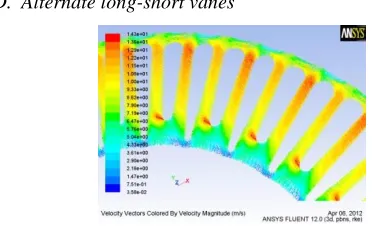
[image:4.612.353.532.212.311.2]D. Alternate long-short vanes
Figure 9: Typical velocity contour plot for the long-short vane geometry
[image:4.612.49.236.296.405.2]Rotor design with alternate long and short vanes was also analysed. In this modification, the vane radial lengths were kept constant for alternate vanes. As seen in figure 10, this design modification did not enhance the heat transfer rate. Hence, this modification was not considered for further study.
Figure 10: Comparison of heat transfer rate between straight and long-short vanes
V. PROCEDURE FOR OPTIMISATION OF VDBR
Basic trends obtained from the 2D analysis described in the previous section were used as a guideline for detailed 3D analysis and optimization. The results obtained in 3D investigations were consistent with the 2D results.
The following modifications found effective in heat transfer enhancement:
a) Curving of vanes
b) Increasing the number of vanes.
These two modifications were first explored independently and then their combined effect was investigated by employing combination of number of vanes and curvature of the curved vanes.
VI. RESULTS
A. Number of vanes
Nine different rotors with 32, 36, 40, 44, 48, 52, 53, 54 and 55 vanes were chosen to evaluate the effects of vane number on the heat transfer rate.
[image:4.612.52.238.552.665.2]International Journal of Emerging Technology and Advanced Engineering
Website: www.ijetae.com (ISSN 2250-2459,ISO 9001:2008 Certified Journal, Volume 5, Issue 7, July 2015)
[image:5.612.334.555.124.260.2]63
Figure 11: Effect of number of vanes on the heat transfer rateB. Effect of curvature
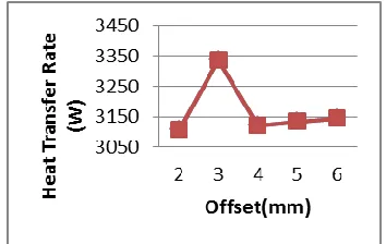
Different offsets ranging from 1 mm to 6 mm were chosen to analyse the case. The results for the heat transfer rate are shown in figure 12.
Figure 12: Effect of offset (curvature) on the heat transfer rate
As the offset increased, the heat transfer rate increased till 3mm and then started decreasing for values above that. It was found that the maximum heat transfer rate is obtained for an offset of 3 mm for the 36 vane configuration.
C. Combination of A and B
Combinations of the two modifications mentioned above were studied. The vane numbers taken for this were varied from 40 to 56 and the offsets from 1 mm to 4 mm. The results in figure 13 are shown for vane numbers 52 to 55, since these yielded the best heat transfer rates.
[image:5.612.94.246.134.248.2]Figure 14 provides the surface plot obtained by simulating all the combinations mentioned above. It shows that the maximum heat transfer rate was obtained for 53 vanes using a backward curvature with an offset of 3 mm. It is thus the optimum design point within the range of this analysis.
Figure 13: Plot of heat transfer rate with varying number of vanes and offset (curvature)
Figure 14: 3D surface plot of heat transfer rate with varying number of vanes and offset (curvature)
VII. CONCLUSIONS AND DISCUSSIONS
1. Increasing the vane number from 36 to 53 yields an increase of 8.93% in the heat transfer rate in comparison with the non-modified rotor.
2. Increasing the curvature to 3 mm for a 36 vane rotor yields an increase of 8.76% in the heat transfer rate in comparison with the non-modified rotor.
[image:5.612.336.551.292.443.2] [image:5.612.79.256.322.434.2]International Journal of Emerging Technology and Advanced Engineering
Website: www.ijetae.com (ISSN 2250-2459,ISO 9001:2008 Certified Journal, Volume 5, Issue 7, July 2015)
64
4.A rotor with cross-drilling on its surface above the flow passage may give higher heat transfer rates due to influence of the flow through the holes. But this modification would require extensive structural analysis. Hence it is not considered in this work. Modifications like providing circular or helically grooved baffles between the two discs instead of regular flow passages are suggested in the literature [14, 15]. However, due to the complex manufacturing procedures required for implementation, these are not investigated in this work.
REFERENCES
[1] Li, Sun, and Liu Yong-chen. "The disc brake design and performance analysis. "Consumer Electronics, Communications and Networks (CECNet), 2011 International Conference on. IEEE, 2011.
[2] Adamowicz, Adam, and Piotr Grzes. "Influence of convective cooling on a disc brake temperature distribution during repetitive braking." Applied Thermal Engineering 31.14 (2011): 2177-2185.
[3] Mazidi, H., et al. "Mathematical modeling of heat conduction in a disk brake system during braking." Asian Journal of Applied Sciences 4.2 (2011): 119-136.
[4] Kapil Shelar, Shivprakash Barve, Mahesh Chopade and Pramod Chaudhari. "Thermal Analysis of Automotive Brake Rotors." International Journal of Current Engineering and Technology Special Issue-3 (2014): 129-132.
[5] McPhee, Adam D., and David A. Johnson. "Experimental heat transfer and flow analysis of a vented brake rotor." International journal of thermal sciences 47.4 (2008): 458-467.
[6] Cengel, Yunus A. Fluid mechanics. Tata McGraw-Hill Education, 2010.
[7] Anderson, John David, and J. Wendt. Computational fluid dynamics. Vol. 206. New York: McGraw-Hill, 1995.
[8] Song, B-C., and K-H. Lee. "Structural optimization of a circumferential friction disk brake with consideration of thermoelastic instability." International Journal of Automotive Technology 10.3 (2009): 321-328.
[9] Adamowicz, Adam, and Piotr Grzes. "Analysis of disc brake temperature distribution during single braking under non-axisymmetric load." Applied Thermal Engineering 31.6 (2011): 1003-1012.
[10] Agarwal, Pulkit, Mayur Shrikhande, and P. SINIVASAN. "Heat transfer simulation by CFD from fins of an air cooled motorcycle engine under varying climatic conditions." Proceedings of the World Congress on Engineering. Vol. 3. 2011.
[11] ANSYS, ICEM CFD. "13.0, User’s Manual, ANSYS."
[12] Fluent, ANSYS. "13.0 Documentation." Ansys Inc.
[13] Yahya, S. M. Turbines compressors and fans. Tata McGraw-Hill Education, 2010.
[14] Mokheimer, Esmail MA. "Performance of annular fins with different profiles subject to variable heat transfer coefficient." International Journal of Heat and Mass Transfer 45.17 (2002): 3631-3642. [15] Bergman, Theodore L., Frank P. Incropera, and Adrienne S. Lavine.