© 2016, IRJET ISO 9001:2008 Certified Journal Page 241
Performance Evaluation of FPGA Based Runtime Dynamic Partial
Reconfiguration for Matrix Multiplication
Mr. Chakradhar V. Borkute, Prof. A. Y. Deshmukh
M.E. (Electronics) Student, G.H.Raisoni College of Engineering, Nagpur-440016
Head-Electronics Engg Deputy Director & Dean(Planning& Quality Assurance) G.H.Raisoni College of Engineering
Nagpur-440016
---***---Abstract-
As the speed and size of FPGA reconfigurablefabric has grown the ability to perform multiple complex parallel applications on a single device has become a reality. Currently, when a device is partially reconfiguring an area of the fabric, the fabric resource is not available to the system. Therefore, increasing the speed at which the device is reconfigured increases the availability of the reconfigurable resource [3].In this paper, the implementation of matrix multiplication using FPGA-Based computing platform is investigated. This matrix multiplier is modeled in Verilog. The design is reconfigured by changing partial modules at run time.ISE13.1 & Planahead is used for partial reconfiguration of FPGA. The complete hardware implementation is done on Xilinx VIRTEX -5 ML506 Platform. The comparative results shown in terms of speed & frequency. The Results shows the static and dynamic areas partitioning in planahead. The test setup and flow for the Dynamic partial reconfiguration is explained in detail. The implementation platform and hardware architecture differences are outlined. Result shows that Transmission and reception Speed Microblaze processor on ML506 platform is high compared to PPC (PowerPC) on ML410 platform.
Keywords:
Partial
Reconfiguration,
Field
Programmable Gate Array (FPGA), Virtex-5, Truncated
Multiplier VHDL
1.
INTRODUCTION
Xilinx partial reconfiguration extends the inherent flexibility of the FPGA by allowing specific regions of the FPGA to be reprogrammed with new functionality while applications continue to run in the remainder of the device. Partial reconfiguration addresses three fundamental needs by enabling [1]
Reduce cost and/or board space Change a design in the field
Reduce power consumption
The two most prevalent user problems, addressed by partial reconfiguration are:
Fitting more logic into an existing device
Fitting a design into a smaller, less expensive device
Historically, designers have spent days, if not weeks, trying new implementation switches, reworking code,
And reengineering solutions to squeeze them into the smallest possible FPGA.
© 2016, IRJET ISO 9001:2008 Certified Journal Page 242 While synthesis and implementation tools coupled with
appropriate design techniques can help reduce power consumption, partial reconfiguration implementations can further reduce static and dynamic power. One way to reduce static power is to simply use a smaller device. With partial reconfiguration, designers can essentially time slice the FPGA and run parts of their design independently. The design then requires a much smaller device or fewer devices because not every part of the design is needed 100% of the time. Partial reconfiguration also has the potential to reduce operating power as well as static power. The SOC implementation [4] is one of the advantage of the partial reconfiguration is the reduced size & complexity as shown in Fig.1.
Fig-1: Modifying Functionality and reducing size using partial reconfiguration
Dynamic Partial Reconfiguration (DPR) allows the part of FPGA device be modified while rest of the device (or system) continues to operate and unaffected by the programming [1]. Module-based partial reconfiguration was proposed by Xilinx [3][4]. And now many researchers have proposed many partial reconfiguration methods (JBits, PARBIT, etc.)[1][2].The modular design flow allows the designer to split the whole system into modules.
2.
IMPLEMENTATION METHODOLOGY
In this thesis Partial Reconfiguration architecture of implementation of 2×2 and 4×4 multipliers using Very High speed integrated circuit Hardware Description Language. Multiplier is a core operation for digital signal processing (DSP) applications such as finite impulse response
(FIR) and discrete cosine transform (DCT). The implementation of DSP algorithm requires Application Specific Integrated Circuits (ASICs). The image processing applications require real time conditions and the
algorithms should be verified and optimized before implementation which cannot be done with ASICs because they are not reconfigurable and cost is very high. The FPGA is a viable technology that could be implemented and reconfigured at the same time, since FPGA have the benefit of hardware speed and the flexibility of software. Xilinx partial design flow has been followed. We have implemented Partial Reconfiguration (PR) design from HDL synthesis through bit file generation and download. Xilinx software tools ISE 13.2 has been used to implement and analyze the design through the PlanAhead software. The complete hardware implementation has been done on Xilinx VIRTEX -5 ML506 Platform.
3.
PROPOSED ARCHITECTURE
Modern FPGAs (e.g. Xilinx Virtex-4, 5, 6 And 7 Series FPGAs) offer the partial reconfiguration capability to dynamically change part of the design without stopping the remaining system. This feature enables alternate utilization of on FPGA programmable resources, therefore resulting in large benefits such as more efficient resource utilization and less static power dissipation. In the design procedure, a Partially Reconfigurable Region (PRR) A is reserved in the overall design layout mapped on the FPGA. Various functional Partially Reconfigurable Modules are individually implemented within this region, and their respective partial bit streams are generated and collectively initialized in a design database residing in memory devices in the system. With a new module bit stream overwriting the original one in the FPGA configuration memory, the PRR is loaded with the new module and the circuit functions according to its concrete design. In the dynamic reconfiguration process, the PRR has to stop working for a short time reconfiguration overhead) until the new module is completely loaded. The static portion of the system will not be disturbed at all.
The partially reconfigurable part delegates those modules with dynamically swapping needs in the PR region.
© 2016, IRJET ISO 9001:2008 Certified Journal Page 243 PRMs from being merged with the one in the base
design.
Each PRR will be only restricted in the area defined by the RANGE constraints. Then after the following individual implementation of the base system and PR modules, the final step in the design flow is to merge them and create both a complete bitstream (with default PR modules equipped) and partial bitstreams for PR modules. Hence, run-time reconfiguration will be initiated when a partial bitstream is loaded into the FPGA configuration memory and overwrites the corresponding segment.
Fig- 2: Xilinx PR Flow
4.
DESIGN AND IMPLEMENTATION
However, with recent advancements in very large scale integration (VLSI) technology, hardware implementation has become a desirable alternative. Significant speedup in computation time can be achieved by assigning computation intensive tasks to hardware and by exploiting the parallelism in algorithms. To date, field programmable gate arrays (FPGAs) have emerged as a platform of choice for efficient hardware implementation of computation intensive algorithms. FPGAs enable a high degree of parallelism and can achieve orders of magnitude speedup over general purpose processors (GPPs). This is a result of increasing embedded resources available on FPGA. FPGA have the benefit of hardware speed and the flexibility of software. The three main factors that play an important role in FPGA based design are the targeted FPGA architecture, electronic design automation (EDA) tools and design techniques employed at the algorithmic level using
hardware description languages. FPGA has become viable technology and an attractive alternative to ASICs Multiplication and squaring functions are used extensively in applications such as DSP, image processing and multimedia. A full width digital n*n multiplier computes the 2n output as a weighted sum of partial products. If the product is truncated to n-bits, the least significant columns of the product matrix contribute little to the final result. To take advantage of this, truncated multipliers and squares do not form all of the least significant columns in the partial-product matrix. As more columns are eliminated, the area and power consumption of the arithmetic unit are significantly reduced, and in many cases the delay also decreases. The trade-off is that truncating the multiplier matrix introduces additional error into the computation. Other applications, which require not only a significant number of multiplication and squaring functions but also large integers, are found in the cryptography domain. Achieving efficient realization of the multiplication may have a significant impact on the specific applications in terms of speed, power dissipation and area. Many research efforts have been presented in literature to achieve hardware efficient implementation of a matrix multiplier. The basic idea of these techniques is to discard some of the less significant partial products and to introduce a compensation circuit that partly compensates for the dropped terms, thereby reducing approximation error. High speed multiplication is desired in DSP which is normally achieved by parallel processing and pipelining. Fig.3 shows the layout of reconfigurable architecture.
© 2016, IRJET ISO 9001:2008 Certified Journal Page 244
5. TEST PLATFORM & HARDWARE SET UP
Dynamic partial reconfiguration code for matrix multiplication is synthesized using Xilinx ISE 13.2, and was implemented using Xilinx Plan Ahead 13.2. The system will be hardware validated by testing it on a Xilinx ML505 evaluation board, which contains a Virtex 5 XC5Vsx110T FPGA.
Fig- 4: Hardware set up
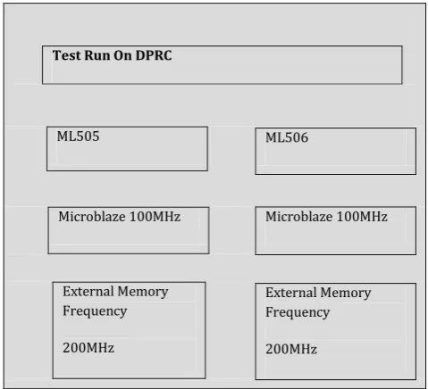
The Dynamic Partial Reconfiguration core was designed to target Virtex-4, Virtex-5 and Virtex-6 FPGAs along With all of the Processors offered by Xilinx for these devices. Fig.5 shows the test platform overview. To accomplish this, a cross platform verification approach was necessary. This included developing multiple embedded systems implemented on the target devices.
Test Run On DPRC
ML505
Microblaze 100MHz
External Memory Frequency
200MHz
ML506
Microblaze 100MHz
External Memory Frequency
200MHz
Fig-5: DPR test designs
ML506 & ML505 evaluation boards were the chosen platforms for the Virtex-5 devices they are populated with,
their availability and extensive documentation. The new Virtex-6 FPGA could not be tested because of its current limited availability.
6.
RESULTS
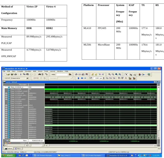
[image:4.595.58.230.220.326.2] [image:4.595.41.281.466.684.2]The four implementations of IDPR controllers consisted of a Virtex-4 PowerPC design, Virtex-5 MicroBlaze design, Virtex-5 PowerPC design with 200MHz DDR2 and Virtex-5 PowerPC design with 266MHz DDR2. Table 1 below outlines the architectural differences. Fig.6 & Fig.7 shows the simulation results for the matrix multiplication of 2X2 Matrix and 4X4 Matrix Respectively. The design is implemented using a Hardware description Language (HDL) language .The design is simulated using a Model SE Simulator. Table 2 represents the previous maximum speed at which the FPGA could be configured using IDPR. Table 3 represents the measured speed of ICAP writes and read throughput. The difference in the speed at which the different systems are capable of reconfiguring can be accounted for by the clock speed at which the systems external memory wasran at, the hard vs. soft memory cross bar and the width of the memory controller’s fabric side bus.
© 2016, IRJET ISO 9001:2008 Certified Journal Page 245
Table- 2: Previously reported state of the art calculated
and measured values [1]
[image:5.595.32.557.144.650.2]Table -3: DPR Measured Values
Fig- 6: Results For 2 X 2 Matrix Multiplication Using Partial Reconfiguration Method of
Configuration
Virtex-2P Virtex-4
Frequency 100MHz 100MHz
Main Memory DDR DDR2
Measured
PLB_ICAP
89.9Mbytes/s 295.4Mbytes/s
Measured
OPB_HWICAP
4.77Mbytes/s 5.07Mbytes/s
Platform Processor System
Freque ncy
(Mhz)
ICAP
Freque ncy
TX RX
ML410 PPC405 200
MHz
100MHz 177.4
Mbytes/s 180.0
Mbytes/ s
ML506 MicroBlaze 200
MHz
100MHz 178.6
Mbytes/s 181.0
© 2016, IRJET ISO 9001:2008 Certified Journal Page 246
Fig- 7: Results For 4 X 4 Matrix Multiplication Using Partial Reconfiguration
REFERENCES
[1] C. Claus, B. Zhang, W. Stechele, L. Braun, M. H¨ubner and J. Becker"A Multi-Platform Controller Allowing For Maximum Dynamic Partial Reconfiguration Throughput,"
IEEE, pp. 535-538, 2008.
[2] L. Boland, "Formula 1 Racing: The Xilinx Advantage,"
Xcell Journal, pp. 46-49, 2003.
[3] Vera, Guillermo, “A Dynamic Arithmetic Architecture: Precision, Power and performance Considerations”, PhD Dissertation, The University of New Mexico,2008.
[4] Xilinx, Virtex-4 Family Overview (UG070). San Jose CA: Xilinx Inc., December 1, 2008.
[5] Xilinx. Xilinx. [Online]. HYPERLINK
"http://www.xilinx.com/company/gettingstarted/index.h tm"
[6] The Design Warrior's Guide to FPGAs. Elsevier Science & Technology Books, 2004.
[7] Xilinx, "Early Access Partial Reconfiguration User Guide (UG208)," 2006. [Online].
HYPERLINK
"http://www12.informatik.uni-erlangen.de/esmwiki/images/f/f3/Pr_flow.pdf"
[8] Xilinx. (2009, Jun.) www.Xilinx.com. [Online]. HYPERLINK
"http://www.xilinx.com/support/documentation/user_gu ides/ug071.pdf"
[9] Xilinx. (2007, Jan.) www.Xilinx.com. [Online]. HYPERLINK
"http://www.xilinx.com/support/documentation/user_gu ides/ug011.pdf"
[10] Xilinx. (2009, Jan.) www.Xilinx.com. [Online]. HYPERLINK
"http://www.xilinx.com/support/documentation/user_gu ides/ug200.pdf"
[11] Xilinx. (2008, Jan.) www.xilinx.com. [Online]. HYPERLINK
"http://www.xilinx.com/support/documentation/sw_ma nuals/mb_ref_guide.pdf"
[12] J. Lucero. (2008, Oct.) Xilinx.com. [Online]. HYPERLINK
"http://www.xilinx.com/support/documentation/applicat ion_notes/xapp1121.pdf"
[13] Xilinx. (2003, Oct.) Xilinx. [Online]. HYPERLINK "http://www.xilinx.com/support/documentation/ip_docu mentation/plb_ddr.pdf"
[14] Xilinx. (2008, Jun.) Xilinx.com. [Online]. HYPERLINK "http://www.xilinx.com/support/documentation/ip_docu mentation/mpmc.pdf"
[15] Xilinx. (April, ) Xilinx.com. [Online]. HYPERLINK "http://www.xilinx.com/support/documentation/ip_docu mentation/ppc440mc_ddr2.pdf"
[16] Xilinx. (2009, Mar.) www.Xilinx.com. [Online]. HYPERLINK
"http://www.xilinx.com/support/documentation/user_gu ides/ug192.pdf"
[17] Xilinx. (2009, Feb.) www.Xilinx.com. [Online]. HYPERLINK
"http://www.xilinx.com/support/documentation/user_gu ides/ug191.pdf"
© 2016, IRJET ISO 9001:2008 Certified Journal Page 247 "http://www.xilinx.com/support/documentation/boards_
and_kits/ug085.pdf"
[19] Xilinx. (2008, Nov.) www.Xilinx.com. [Online]. HYPERLINK
"http://www.xilinx.com/support/documentation/boards_ and_kits/ug347.pdf"
[20] Ju¨rgen Becker, Michael Hu¨bner, Gerhard Hettich, Rainer Constapel, Joachim Eisenmann,and Ju¨rgen Luka, "Dynamic and Partial FPGA Exploitation," Proceedings of the IEEE Vol.95, No. 2, February, pp. 438-452, 2007.
[21] Xilinx. (2006, Feb.) Xilinx. [Online]. HYPERLINK http://www.xilinx.com/prs_rls/dsp/0626_sdr.htm [22] D. R. a. J. R. Kenny. (2008, Oct.) Two competitive FPGA methodologies for run-time reconfiguration. [Online]. HYPERLINK
"http://www.dsp-fpga.com/articles/id/?3636" [23] Xilinx. (2007, Aug.) Xilinx. [Online]. HYPERLINK "http://www.xilinx.com/support/documentation/ip_docu mentation/xps_hwicap.pdf"
BIOGRAPHIES
C. V. Borkute, he has completed his
Graduation in Electronics
Engineering. He is CEO at Qualitat systems, Pune (India).
Perusing Master of Engineering from G. H. Raisoni College of Engineering, Nagpur. He has 10+ years of experience in VLSI & embedded domain. His area of interest is embedded system & VLSI
Dr. A. Y. Deshmukh, he has completed his Ph.D from VNIT Nagpur in 2010. He is currently working as Deputy Director, Dean-Planning & Quality assurance at G.H.Raisoni College of Engineering Nagpur, India. He has filed 02 Patents. He is also working as Coordinator TEQIP-II (World Bank Assistance Project). He is Technical Committee Member of IEEE Soft Computing, USA. He is also Counselor of IEEE Students Branch. He has around 50 International Conference and Journal Publications. He has also worked as International Co-Chair & reviewer & Session Chair for many