© 2016, IRJET | Impact Factor value: 4.45 | ISO 9001:2008 Certified Journal | Page 2301
AN ANALYTICAL STUDY ON OUTRIGGER STRUCTURES USING NON
LINEAR DYNAMIC TIME HISTORY ANALYSIS
KOMAL JAIN.J
1, Mr.G.SENTHIL KUMAR
21 1
Master of Technology, Department of Civil Engineering, SRM University, Chennai, Tamil Nadu, India
2
Assistant Professor, Department of Civil Engineering, SRM University, Chennai, Tamil Nadu, India
---***---Abstract - Skyscrapers is ineluctable in modern world,
especially in developing nations and is prone to structural damage by natural disaster, were the taller part of the structure gets greater acceleration due to gravity resulting in a higher drift value .The role of a outrigger is inexorable in controlling the storey drift and overturning moment. Outrigger with or without belt trust system plays a vital role in providing stiffness to the structure. A prototype with sixty storey is taken into consideration with symmetrical plan and asymmetrical plan. Various models with outrigger are modeled in form of bracings and placed at various heights by attaching it to the shear walls externally. The optimized value is obtained by considering the various factors such as drift, displacement, base shear and time history analysis that is calculated using static and dynamic analysis.
Key Words: With belt truss, without belt truss, Response analysis, Time History Analysis
1.INTRODUCTION
The outrigger and belt truss system is commonly used as one of the structural system to effectivelycontrol the excessive drift due to lateral load, so that, during small or medium lateral load due toeither wind or earthquake load, the risk of structural and non-structural damage can be minimized. For high-rise buildings, particularly in seismic active zone or wind load dominant, this system can be chosen as an appropriate structure. Optimum Location of Outrigger-belt Truss in Tall Buildings Based on Maximization of the Belt Truss Strain Energy discusses the methodology for determining the optimum location of an outrigger-belt truss
system[1].Although outriggers have been used for approximately four decades, their existence as a structural member has a much longer history.
Outriggers have been used in the sailing ship industry for many years. They are used to resist wind. The slender mast provides the use of outriggers. As a comparison the core can be related to the mast, the outriggers are like the spreaders and the exterior columns are like the shrouds or stays. Innovative structural schemes are continuously being sought in the field. Structural Design of High Rise Structures with the intention of limiting the Drift due to Lateral Loads to acceptable limits without paying a high premium in steel tonnage. Ductility of a 60-Story Shear wall Frame-Belt Truss(Virtual Outrigger) Building discuss the Static non-linear push over analysis is a simple alternative method in evaluating structure behavior under dynamic loading. In this study, with the complexity of vertical stiffness distribution with the existence of belt truss, static non-linear push over analysis shows its limitation [2]. The savings in steel tonnage and cost can be dramatic if certain techniques are employed to utilize the full capacities of the structural elements.
© 2016, IRJET | Impact Factor value: 4.45 | ISO 9001:2008 Certified Journal | Page 2302 structural form consists of a central core, comprising either
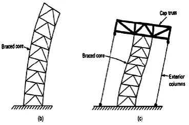
Braced Frames or Shear Walls, with horizontal cantilever trusses or girders known as outrigger Trusses, connecting the core to the outer columns. A study for the optimum location of outriggers for high-rise concrete Buildingsshows that the use of outrigger in high-rise buildings increase the stiffness and makes the structural form efficient under lateral load, On increasing number of outriggers top storey maximum drift was decreased, Provision of outriggers at regular intervals from the top of the building was effective in reducing the overall drift of the building and the behavior of outrigger with belt truss proven to be more effective when compared to that of the outrigger without belt truss[4]. The core may be centrally located with outriggers extending on both sides (Fig.1.a) or it may be located on one side of the building with outriggers extending to the building columns on one side (Fig.1.b). When Horizontal loading acts on the building, the column restrained outriggers resist the rotation of the core, causing the lateral deflections and moments in the core to be smaller than if the free standing core alone resisted the loading.
Fig.1 (a) Outrigger system with a central core (b) Outrigger system with offset core
Analysis Of Outrigger System For Tall Vertical Irregularities Structures Subjected To Lateral Loads considers a three dimensional model is considered and designed for the gravity load and placing of first and second
position of the outrigger and seen that the use of outrigger and belt truss system in high-rise buildings increase the stiffness and makes the structural form efficient under lateral load [5].The result is to increase the effective depth of the structure when it flexes as a vertical cantilever, by inducing tension in the windward columns and Compression in the leeward columns. Optimum Position of Outrigger System for High-Rise Reinforced Concrete Buildings under Wind and Earthquake Loadings shows that as the building increases in height, the stiffness of the structure becomes more important and introduction of outrigger beams between the shear walls and external columns is often used to provide sufficient lateral stiffness to the structure [6].
© 2016, IRJET | Impact Factor value: 4.45 | ISO 9001:2008 Certified Journal | Page 2303 least for outrigger structure with relative height of 0.5 for all
earthquake history [8]. And finally, girders at each floor may be transformed into outriggers by moment connections to the core and, if desired, to the exterior columns as well.A Study on Dynamic Analysis of Tall Structure with Belt Truss Systems for Different Seismic Zones contains a comparative study on type of belt truss has been used which provide more economical for human beings under different seismic zone criteria with and without shear core for building. The modeling of the structure is done using ‘ETABS” software. The analysis of the model is carried out by equivalent static method and response spectrum method [9].Here, it should be noted that while the outrigger system is very effective in increasing the structure’s flexural stiffness, it doesn’t increase its resistance to shear, which has to be carried mainly by the core.
1.1 Problems With Outriggers
There are several problems associated with the use of outriggers, problems that limit the applicability of the concept in the real world:
1. The space occupied by the outrigger trusses (especially the diagonals) places constraints on the use of the floors at which the outriggers are located. Even in mechanical equipment floors, the presence of outrigger truss members can be a major problem. 2. Architectural and functional constraints may
prevent placement of large outrigger columns where they could most conveniently be engaged by outrigger trusses extending out from the core. 3. The connections of the outrigger trusses to the core
can be very complicated, especially when a concrete shear wall core is used.
4. In most instances, the core and the outrigger columns will not shorten equally under gravity load.
The outrigger trusses, which need to be very stiff to be effective as outriggers, can be severely stressed as they
try to restrain the differential shortening between the core and the outrigger columns. Elaborate and expensive means, such as delaying the completion of certain truss connections until after the building has been topped out, have been employed to alleviate the problems caused by differential shortening [10].
1.2 BEHAVIOR OF OUTRIGGERS
To understand the behavior of an outrigger system, consider a building stiffened by a story high outrigger at top, as shown in Fig.1.2.c. Because the outrigger is at the top, the system is often referred to as a cap or hat truss system. The tie-down action of the cap truss generates a restoring couple at the building top, resulting in a point of contra-flexure in its deflection curve. This reversal in curvature reduces the bending moment in the core and hence, the building drifts. The core may be considered as a single-redundant cantilever with the rotation restrained at the top by the stretching and shortening of windward and leeward columns. The result of the tensile and compressive forces is equivalent to a restoring couple opposing the rotation of the core. Therefore, the cap truss may be conceptualized as a restraining spring located at the top of the cantilever. Its rotational stiffness may be defined as the restoring couple due to a unit rotation of the core at the top [10].
© 2016, IRJET | Impact Factor value: 4.45 | ISO 9001:2008 Certified Journal | Page 2304
Fig.1.2 (b) Cantilever bending of core (c) tie-down action of cap truss
2. MODELS CONSIDERED FOR ANALYSIS
High rise super structure of 20,30,35,45 storey having 40x40 m (Fig 2.1and 2.2) plan dimension with each storey height of 4 m with the column and beam whose dimensions are 1.2 x1.2m and 1.2x0.9m is taken into consideration. The bracing system size is 0.23x0.6m is used whose Grade of concrete is M40 and grade of steel is Fe500. Seismic load are used as per IS 1893-2002 specified standards. The dynamic analysis is performed using Response spectrum Method ,In response spectrum method design parameter for horizontal seismic coefficient is seismic zone factor(Z)=0.36(zone -5),soil types is medium soil .damping is 5%,importance factor (I)is 1, and Response reduction factor (R)is 4.The nonlinear time history analysis is carried out by considering El-Centro time history data. Comparison between structures is carried out the parameter such as time period, base shear, displacement, storey drift, and acceleration are taken into consideration for comparison using SAP2000v18.
[image:4.595.68.253.98.220.2]Fig 2.1: Symmetrical plan view
Fig 2.2: Asymmetrical plan view
The method of analysis of the above mentioned system is based on the following assumptions.
The outriggers are rigidly attached to the core
The core is rigidly attached to the foundation
Tensional effects are not considered.
Material behavior is in linear elastic range.
For earthquake resistant designs, a structure should meet performance requirements at two different levels, depending upon the earthquake action. The first level requires structural response in the elastic range without significant structural damage under a moderate earthquake action and the second level of performance requires that the structure doesn’t collapse under a severe earthquake event with rare occurrence.
3. RESULT AND DISCUSSION
A) SYMMETRICAL STRUCTURE
3.1 Natural Time Period
The natural time period is plotted with respect to the 60 storey’s of the structure with different place for outrigger.
Table 3.1: Time Period for with and without belt truss
Types of models
With belt truss (sec)
Without belt truss(sec)
Without outrigger
5.53 5.53
20 7.62 10.49
© 2016, IRJET | Impact Factor value: 4.45 | ISO 9001:2008 Certified Journal | Page 2305
35 10.56 10.58
[image:5.595.52.281.80.301.2]45 10.64 10.65
Fig 3.1: Comparison between for with and without belt truss
The figure 3.1 is plotted based on the table 3.1 values for Symmetrical structure of natural time period. Depicting the chart showing the symmetrical structure strand namely with and without belt truss with regard to without outrigger, 20,30,35,45 storey.
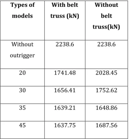
3.2 Base Shear
[image:5.595.294.542.414.750.2]The base shear is plotted with respect to the 60 storey’s of the structure with different place for outrigger.
Table 3.2: Base shear for with and without belt truss
Types of models
With belt truss (kN)
Without belt truss(kN)
Without outrigger
2238.6 2238.6
20 1741.48 2028.45
30 1656.41 1752.62
35 1639.21 1648.86
45 1637.75 1687.56
Fig 3.2: Comparison between for with and without belt truss
The figure 3.2 is plotted based on the table 3.2 values for Symmetrical structure of base shear. Depicting the chart showing the symmetrical structure strand namely with and without belt truss with regard to without outrigger, 20,30,35,45 storey.
3.3 Storey Displacement
The Storey displacement is plotted with respect to the 60 storey’s of the structure with different place for outrigger.
Table 3.3: Displacement for with and without belt truss
Types of models
With belt truss (mm)
Without belt truss(mm)
Without outrigger
766.53 766.53
20 374.8 398.46
30 402.97 401.5
35 401.38 402.97
45 405.21 405.98
[image:5.595.59.267.505.728.2]© 2016, IRJET | Impact Factor value: 4.45 | ISO 9001:2008 Certified Journal | Page 2306
Fig 3.3.b: Comparison between for without belt truss. The figure 3.3.a and 3.3.b is plotted based on the table 3.3 values for Symmetrical structure of storey displacement. Depicting the chart showing the symmetrical structure strand namely with and without belt truss with regard to without outrigger, 20,30,35,45 storey.
3.4 Storey Drift
[image:6.595.337.533.115.256.2]The Storey drift is plotted with respect to the 60 storey’s of the structure with different place for outrigger.
Table 3.4: Displacement for with and without belt truss
Types of models
With belt truss (no units)
Without belt truss (no
units)
Without outrigger
0.002375 0.002375
20 0.00075 0.01122
30 0.001123 0.00113
35 0.00107 0.001123
45 0.00112 0.00113
Fig 3.4.a: Comparison between for with belt truss.
Fig 3.4.b: Comparison between for without belt truss. The figure 3.4.a and 3.4.b is plotted based on the table 3.4 values for Symmetrical structure of storey drift. Depicting the chart showing the symmetrical structure strand namely with and without belt truss with regard to without outrigger, 20,30,35,45 storey.
3.5 Acceleration
[image:6.595.36.544.409.792.2]The acceleration is plotted with respect to the 60 storey’s of the structure with different place for outrigger.
Fig 3.5.a: Comparison between for with belt truss.
[image:6.595.334.537.429.557.2]© 2016, IRJET | Impact Factor value: 4.45 | ISO 9001:2008 Certified Journal | Page 2307 with and without belt truss with regard to without outrigger,
20,30,35,45 storey.
B) ASYMMETRICAL STRUCTURE
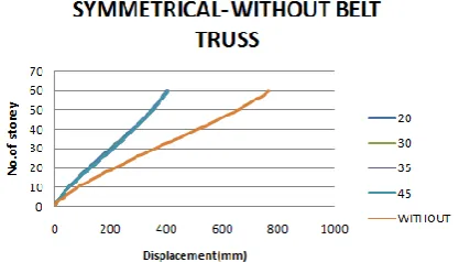
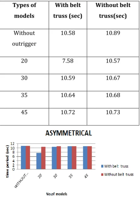
3.6 Natural Time Period
[image:7.595.324.541.111.508.2]The natural time period is plotted with respect to the 60 storey’s of the structure with different place for outrigger.
Table 3.6: Time Period for with and without belt truss
Types of models
With belt truss (sec)
Without belt truss(sec)
Without outrigger
10.58 10.89
20 7.58 10.57
30 10.59 10.67
35 10.64 10.68
45 10.72 10.73
Fig 3.6: Comparison between for with and without belt truss.
The figure 3.6 is plotted based on the table 3.6 values for Asymmetrical structure of natural time period. Depicting the chart showing the asymmetrical structure strand namely with and without belt truss with regard to without outrigger, 20,30,35,45 storey.
3.7 Base Shear
The base shear is plotted with respect to the 60 storey’s of the structure with different place for outrigger.
Table 3.7: Base shear for with and without belt truss
Types of models
With belt truss (kN)
Without belt truss(kN)
Without outrigger
2538.6 2538.6
20 1856.69 2238.69
30 1796.34 1836.65
35 1791.85 1824.34
[image:7.595.47.278.242.568.2]45 1782.96 1810.96
Fig 3.7: Comparison between for with and without belt truss
The figure 3.7 is plotted based on the table 3.7 values for Asymmetrical structure of base shear. Depicting the chart showing the asymmetrical structure strand namely with and without belt truss with regard to without outrigger, 20,30,35,45 storey.
3.8 Storey Displacement
[image:7.595.46.278.243.563.2]© 2016, IRJET | Impact Factor value: 4.45 | ISO 9001:2008 Certified Journal | Page 2308 Table 3.8: Displacement for with and without belt truss
Types of models
With belt truss (mm)
Without belt truss(mm)
Without outrigger
641.5 641.5
20 372 406.72
30 401.3 409.85
35 410.01 411.34
[image:8.595.317.551.204.574.2]45 413.08 414.44
Fig 3.8.a: Comparison between for with belt truss.
Fig 3.8.b: Comparison between for without belt truss. The figure 3.8.a and 3.8.b is plotted based on the table 3.3 values for Asymmetrical structure of storey displacement. Depicting the chart showing the symmetrical
structure strand namely with and without belt truss with regard to without outrigger, 20,30,35,45 storey.
3.9 Storey Drift
The Storey drift is plotted with respect to the 60 storey’s of the structure with different place for outrigger.
Table 3.9: Displacement for with and without belt truss
Types of models
With belt truss (no units)
Without belt truss (no units)
Without outrigger
0.002113 0.002113
20 0.000775 0.001223
30 0.00107 0.000123
35 0.00125 0.00122
[image:8.595.317.551.206.577.2]45 0.001225 0.001215
Fig 3.9.a: Comparison between for with belt truss.
[image:8.595.57.267.495.671.2] [image:8.595.332.536.601.740.2]© 2016, IRJET | Impact Factor value: 4.45 | ISO 9001:2008 Certified Journal | Page 2309 The figure 3.9.a and 3.9.b is plotted based on the
table 3.4 values for Asymmetrical structure of storey drift. Depicting the chart showing the asymmetrical structure strand namely with and without belt truss with regard to without outrigger, 20,30,35,45 storey.
3.10. Acceleration
The acceleration is plotted with respect to the 60 storey’s of the structure with different place for outrigger.
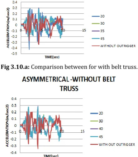
Fig 3.10.a: Comparison between for with belt truss.
Fig 3.10.b: Comparison between for without belt truss. The figure 3.10.a and 3.10.b is plotted based on the values for Asymmetrical structure of acceleration. Depicting the chart showing the asymmetrical structure strand namely with and without belt truss with regard to without outrigger, 20,30,35,45 storey.
4. CONCLUSION
The behavior of outrigger with and without belt truss system is studied in both symmetrical and asymmetrical structure. It is studied that the outrigger with belt truss system is effective in controlling drift of the building. Even in asymmetrical structure is the drift is controlled to the maximum. Hence the outrigger systems
with belt truss improve the performance of the building by resisting the lateral forces. From time history analysis the acceleration is low for outrigger based high rise structure which makes it more stiff and rigid. Location of the outrigger plays a very important role in the design of tall buildings. From this study it is concluded that the performance of the building improves if the outrigger is placed at the mid height of the building.
REFERENCES
[1] P.M.B. Raj Kiran Nanduri, B.Suresh, MD. Ihtesham Hussain” Optimum Position of Outrigger System for High-Rise Reinforced Concrete Buildings under Wind and Earthquake Loadings”, American Journal of Engineering Research Vol. 02, Issue 08, pp.76-89, September 2014.
[2] M. R. Jahanshahi, R. Rahgozar,’’ Optimum Location of Outrigger-belt Truss in Tall Buildings Based on Maximizationof the Belt Truss Strain Energy’’, Int. Journal of Engineering , Vol. 26 Issue: 07 pp.693-700, July-2013.
[3] Kiran Kamath, N. Divya, Asha U Rao,” A Study on Static and Dynamic Behavior of Outrigger Structural System for Tall Buildings”, Bonfring International Journal of Industrial Engineering and Management Science, Vol. 04 Issue: 04 pp.90-96, December-2013.
[4] Mohd Irfan, Moinuddin, Mohd Afroz Khan, ” A Study For The Optimum Location Of Outriggers For High-Rise Concrete Buildings”, Int. Journal of Advanced Trends in Computer Science and Engineering, Vol. 02, Issue: 01, pp.628-633, May -2012.
[5] Shivacharan k, Chandrakala S, Narayana G, Karthik N M,” Analysis Of Outrigger System For Tall Vertical Irregularites Structures Subjected To Lateral Loads”, Int. Journal of Science and Research ,Vol. 4 Issue 5,pp.485-489 May 2012.
[6] Gerasimidis S., Efthymiou E. and Baniotopoulos C. C, Optimum outrigger locations for high rise steel buildings for wind loading, EACWE 5 Florence, Italy, 19th – 23rd July 2012.
[image:9.595.50.272.278.530.2]© 2016, IRJET | Impact Factor value: 4.45 | ISO 9001:2008 Certified Journal | Page 2310 [8] Herath ,” Behavior of Outrigger Beams in High Rise
Buildings Under Earthquake Loads ”, Int. Journal of Advance Engineering and Research Development,Vol. 03, Issue 05,pp.176-189, May 2010.
[9] Vijaya Kumari Gowda M R, Manohar B C, ” A Study on Dynamic Analysis of Tall Structure with Belt Truss Systems for Different Seismic Zones”, Int. Journal of Engineering Research & Technology, Vol.04, Issue: 08, pp.3545, Augest -2010.