Speed Control of DC Motor using Fuzzy Logic based on
LabVIEW
Salim
*, Jyoti Ohri
**,
Naveen
**** Electrical Department, National Institute of Technology Kurukshetra **
Electrical Department, National Institute of Technology Kurukshetra ***Electrical Department, UIET, Kurukshetra University Kurukshetra
Abstract- Speed control of DC Motor is vital in many applications. In this paper, an effort has been made to control the speed of the DC motor using fuzzy logic control (FLC) based on LabVIEW (Laboratory Virtual Instrument Engineering Workbench) program. LabVIEW provides a graphical programming environment suited for high-level or system-level design. The fuzzy logic controller designed to apply the required control voltage that sent to dc motor based on fuzzy rule base of motor speed error (e) and change of speed error (Ce). In this paper results of FLC, PI and PID Controller are compared. The simulation results demonstrate that the response of DC motor with FLC show a satisfactory well damped control performance.
Index Terms- DC Motor, Ziegler-Nichols Tuning, Speed Control, Fuzzy Logic and PID controller, LabVIEW
I. INTRODUCTION
he DC motors have been popular in the industry control area for a long time, because they have many good characteristics, for example: high start torque characteristic, high response performance, easier to be linear control etc. There are different control approaches which depend on the different performance of motors. The basic property of DC motor is that speed can be adjusted by varying the terminal voltage. Therefore, the DC motor control is riper than other kinds of motors. Classic Control has proven for a long time to be good enough to handle control tasks on system control; however its implementation relies on an exact mathematical model of the plant to be controlled and not simple mathematical operations. The fuzzy logic, unlike conventional logic system, is able to model inaccurate or imprecise models. The fuzzy logic approach offers a simpler, quicker and more reliable solution that is clear advantage over conventional techniques. Fuzzy logic may be viewed as form of set theory [1]. When compared to the conventional controller, the main advantage of fuzzy logic is that no mathematical modeling is required. Since the controller rules are especially based on the knowledge of the system behavior and experience of the control engineer, the FLC requires less complex mathematical modeling than classical controller does. LabVIEW is better for control applications and MATLAB is better for data manipulation. LabVIEW is the graphical development environment for creating flexible and scalable test, measurement, and control applications rapidly and at minimal cost.
II. SYSTEM DESCRIPTION
DC MOTOR MATHEMATICAL MODEL - DC motor system is a
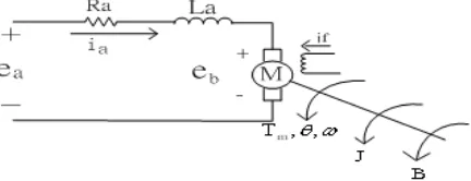
[image:1.612.342.558.303.386.2]separately excited DC motor, which is often used to the velocity tuning and the position adjustment. The equivalent circuit of the DC motor using the armature voltage control method [8] is shown in Figure 1:
Figure 1: Equivalent circuit of the DC motor.
Where
: Armature resistance (3.3Ω) : Armature inductance (0.00464H) : Armature current (A)
: Field current (A)
: Input voltage (V)
: Back electromotive force (EMF) (V) : Motor torque (Nm)
: An angular velocity of rotor (rad/s) J : rotor inertia (9.64E-6kg ) B : Friction constant (1.8E-6Nms/rad)
: EMF constant (0.028Vs/rad) : Torque constant (0.028Nm/A)
Because the back EMF is proportional to speed directly, hence
(1)
Making use of the KCL voltage law we can get
(2)
From Newton law, the motor torque can obtain
Taking Laplace transform, the above equations can be formulated as follows:
(4)
(5)
(6)
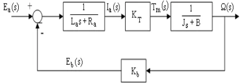
The DC motor armature control system functional block diagram from equations (4) to (6) is shown in Figure 2:
Figure 2: DC motor armature control system functional block diagram.
The transfer function of DC motor speed with respect to the input voltage can be written as follows [11],
(7)
(8)
A LabVIEW based servo control system was built in order to run fuzzy and PID algorithms and also to analyze their works. The control system’s aims are %0.5 or less overshot, No steady state error, Minimum settling time, Minimum rising time.
III. PID CONTROLLER DESCRIPTION AND DESIGN
[image:2.612.48.286.206.289.2]The development of PID control theories has already been from 60 years. PID control has been one of the control system design method of the longest history. However, this method is still extensively used [7] [8]. PID controller is mainly to adjust an appropriate proportional gain ( ), integral gain ( ), and differential gain ( ) to achieve the optimal control performance. These functions have been enough to the most control processes. The PID controller system block diagram is shown in Figure 3:
Figure 3: PID controller system block diagram.
The relationship between the input e(t) and output u(t) can be formulated in the following,
(9)
The transfer function is expressed as follows,
(10)
The PID DC motor speed control system block diagram is shown in Figure 4:
Figure 4: PID DC motor speed control system block diagram
The closed loop transfer function of DC motor speed control system expresses as follows,
(11)
(5)
(12)
Ziegler- Nichols is a type of continuous cycling method for controller tuning. The term continuous cycling refers to a continuous oscillation with constant amplitude and is based on the trial-and-error procedure of changing the proportional gain ( ). is increased from small value till the point at which the system goes to unstable. Thus the gain at which system starts oscillating is noted as ultimate gain ( ) and period of oscillations is ultimate time period ( ). It allows us to use the ultimate gain value, Ku, and the ultimate period of oscillation
( ) to calculate and . These two parameters, and are used to find the loop-tuning constants of the controller (P, PI, or PID) using the formula tabulated in Table I:
Table I: for Ziegler Nichols parameters
Controller
P 0.5 0
PI 0.45 0
[image:2.612.330.561.223.313.2]Then according to Z-N tuning rule, by using ultimate gain and ultimate period P, PI, PID gains and obtained using relation and [14] for DC motor is shown in Table II:
Table II: Simulated results for Ziegler Nichols.
PID controller transfer function for DC motor using Ziegler Nichols tuning method is shown in Equation 13.
U(s) / E(s) (13)
IV. FUZZY CONTROLLER DESCRIPTION & DESIGN
The fuzzy logic foundation is based on the simulation of people's opinions and perceptions to control any system. One of the methods to simplify complex systems is to tolerate to imprecision, vagueness and uncertainty up to some extent [15]. Fuzzy provides a remarkably simple way to draw definite conclusions from vague ambiguous or imprecise information. It is suitable for applications such as the speed control of dc motor which has non-linearities.
A fuzzy control system is a control system in which a mathematical system that analyzes analog input values in terms of logical variables that take on continuous values between 0 and 1, in contrast to classical or digital logic, which operates on discrete values of either 1 or 0 (true or false, respectively). Fuzzy Logic provides a simple way to arrive at a definite conclusion based upon vague, ambiguous, imprecise, noisy, or missing input information. Fuzzy Logic’s approach to control problems mimics how a person makes decisions, only much faster. Fuzziness is connected with the degree to which events occur rather than likelihood of their occurrence.
FLC have some advantages compared to other classical controller such as simplicity of control, low cost and the possibility to design without knowing the exact mathematical model of the process. Fuzzy logic incorporates an alternative way of thinking which allows modeling complex systems using higher level of abstraction originating from the knowledge and experience.
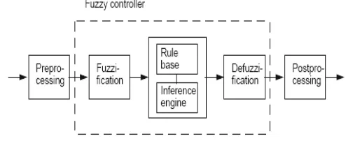
Components Characteristic of a Fuzzy Controller: Preprocessing
Fuzzification Rule Base Defuzzification Post processing
Preprocessing: The inputs are most often hard or crisp measurement from some measuring equipment rather than
linguistic. A preprocessor block in Figure: 5 shows the conditions of measurements before enter the controller.
Fuzzification: The first block inside the controller is fuzzification which converts each piece of input data to degrees of membership by a lookup in one or several membership functions.
Rule Base: The collection of rules is called a rule base. The rules are in “If Then “format and formally the If side is called the
conditions and the Then side is called the conclusion. The
computer is able to execute the rules and compute a control signal depending on the measured inputs error (e) and change in
error (Ce).
Defuzzification: Defuzzification is when all the actions that have been activated are combined and converted in to a single non-fuzzy output signal which is the control signal of the system. The output levels are depending on the rules that the systems have and the positions depending on the non-linearity’s existing to the systems. To achieve the results, develop a control curve of the system representing the I/O relation of the system, and based on the information define the output degree of membership function with the aim to minimize the effect of non-linearity.
Post processing: The post processing block often contains an output gain that can be tuned and also become as an integrator.
An expert operator develops flexible control mechanism using words like "suitable, not very suitable, high, little high and much. Figure 5: Shows process blocks for a fuzzy controller.
Figure 5: Process Blocks for a Fuzzy Controller.
Although the classic controllers depend on the accuracy of the system model and parameters, FLC uses different strategies for motor speed control. Basically, FLC process is based on experiences and linguistic definitions instead of system model. It is not required to know exact system model to design FLC. In addition to this, if there is not enough knowledge about control process, FLC may not give satisfactory results [18].
Defining Input and Output:
The goal of designed FLC in this study is to minimize speed error. In addition, the change of error plays an important role to define controller input. Consequently FLC uses error (e) and change of error (Ce) for linguistic variables which are generated from the control rules. Equation (14) and Equation (15), determines required system equations.
Controller
P 0.5542 0 0
PI 0.4987 85.5540 0
[image:3.612.321.568.426.527.2]e(t) = r(t) – u(t) (14)
(t) = e(t) – e(t-1). (15)
r(t) is desired speed and u(t) is actual speed.
Defining membership functions and rules:
System speed comes to reference value by means of the defined rules. For example, first rule is, 'if e(t) is NA then u(t) is DM'. According to this rule, if error value is negative large then output will be negative large. To calculate FLC output value, the inputs and outputs must be converted from 'crisp' value into linguistic form. Fuzzy membership functions are used to perform this conversion. In this paper, all membership functions are defined between -5 and 5 intervals.
Fuzzy rule data base used are ‘if e(t) is NA then u(t) is DM'. 'if e(t) is NB then u(t) is DB'. 'if e(t) is CERO then u(t) is STR'. 'if e(t) is CERO and Ce(t) is ENA then u(t) is AM'. 'if e(t) is CERO and Ce(t) is EPA then u(t) is DM'. ‘if e(t) is PA then u(t) is AM'. 'if e(t) is PB then u(t) is AP'.
Figure: 6 Membership functions of position error e (t).
Figure: 7 Membership functions of control signal u (t).
V. EXPERIMENTAL RESULTS
The operation of a FLC is based on heuristic knowledge and linguistic description to perform a task. The performance of the FLC is then improved by adjusting the rules and membership function. The designed FLC consists of three components.
Fuzzification of input values Fuzzy inference
Defuzzification of fuzzy output
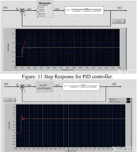
Simulation results for P PI PID and fuzzy controller are shown in Figure: 9 to Figure: 12.
Figure: 8 Sub VI for DC motor using Fuzzy and PID controller.
Figure: 9 Step Response for proportional controller.
Figure: 11 Step Response for PID controller.
Figure: 12 Step Response for Fuzzy controller.
Comparison of PID controller and Fuzzy controller step response specifications are tabulated in Table III.
Tuning rule Response specification
PID Fuzzy logic
Damping ratio 0.46 0.70
Peak time (s) 0.0061 0.00275
Peak value 1.275 1.25
Gain margin ∞ ∞
[image:5.612.35.304.59.356.2]Rise time (s) 0.00325 0.002 Settling time (s) 0.0115 0.007 Dead time (s) 0.00155 0.00125 Table III: Comparison of PID controller and Fuzzy controller.
From the simulation results tabulated in Table III: it is concluded that by step response specifications using Fuzzy controller damping ratio, rise time, settling time, peak value and peak time is better than PID controller. Fuzzy controller results in less oscillation at the control system response. Less oscillations means better controllability and less sensitivity to change in system condition.
VI. CONCLUSION
The results of experiment demonstrate that the proposed fuzzy logic controller is sensitive to variation of the reference speed. The results of the controller are as follows.
1. The speed control of dc motor by proposed controller (FLC)
gains optimal performance.
2. The proposed controller achieved to overcome the disadvantage of conventional controller’s sensitiveness to inertia variation and sensitiveness to variation of the speed with drive system of dc motor.
REFERENCES
[1] Lab VIEW PID Control Toolset User Manual, National Instruments, 2001. Liau, J. C., A Study of Lab-VIEW Aided in DC Motor Speed Monitoring System. National Taiwan Ocean University Department of Mechanical & Mechatronic Engineering, 2000.
[2] Lab VIEW Basics I Course Manual, National Instruments, 1999.
[3] Brian R Copeland, The Design of PID Controllers using Ziegler Nichols Tuning, (March 2008)
[4] Using the Lab-VIEW PID Control Toolkit with the Lab VIEW Control Design and Simulation Module Sep 2009
[5] K.P Ramachandran ‘Control Engineering’Wiley Precise Textbook, 2011. [6] Graham C. Goodwin, Stefan F. Graebe, Mario E. Salgado ‘Classical PID
Control’(Control System Design, Prentice Hall PTR)
[7] PID Control of Continuous Processes by John W. Webb Ronald A. Reis. [8] PC-based PID Speed Control in DC Motor, Guoshing Huang, Shuocheng
Lee, Department of Electronic Engineering, National Chin-Yi University of Technology, 35, Lane 215, Chung-Shan Rd., Sec. 1, Taiping, Taichung, Taiwan, 41111, ROC E-mail:[email protected]
[9] "Getting in tune with Ziegler-Nichols," Thomas R. Kurfess, PhD, in the Academic Viewpoint column, Control Engineering magazine, Feb 2007 issue, p. 28, http://www.controleng.com/.
[10] A more recent survey that covers the Ziegler-Nichols and Kappa-Tau tuning rules: "Automatic Tuning of PID Controllers," Karl J. Åström & Tore Hägglund, Chapter 52, The Control Handbook, IEEE/CRC Press, 1995, William S. Levine ed.
[11] PID Example: DC Motor Speed Control [12] "ACTZiegler-NicholsTuning,"
http://ourworld.compuserve.com/homepages/ACTGMBH/zn.htm
[13] Tuning of PID Controller using Ziegler-Nichols Method for Speed Control of DC Motor.ISBN:978-81-909042-2-3, 2012 IEEE.
[14] J. Yan, M. Ryan and J. Power, Using fuzzy logic toward intelligent system, Prentice Hall, New York,1994.
[15] J.Klir, George, Yuan, Bo. : "Fuzzy Sets and Fuzzy Logic Theory and Applications"
[16] L. A. Zadeh, "Fuzzy Sets" informat Control, vol.8, pp 338-353, 1965. [17] L. A. Zadeh, "Outline of a new approach to the analysis complex systems
and decision processes" IEEE Trans. Syst. Man Cybem, vol.SMC-3, PP. 28-44, 1973.
[18] Y. Tipsuwan, Y. Chow, "Fuzzy Logic Microcontroller Implementation for DC Motor Speed Control", IEEE, 1999.
AUTHORS
First Author – Salim, M.TECH (control system), NIT
Kurukshetra and [email protected].
Second Author – Dr. Jyoti Ohri, Ph.D.