2018 3rd International Conference on Computational Modeling, Simulation and Applied Mathematics (CMSAM 2018) ISBN: 978-1-60595-035-8
System Design of Intelligent Buried Cable Path Detection Device
Xiong-keng ZHAN, Hong-qin YU
*, Gai LI, Hai-ming WU, Ling-hui CHEN,
Song-qing ZOU, Wei-zheng LIANG, Hui HUANG,
Qing-bin WANG and Xiao-ke CHEN
Yunfu Power Supply of Guangdong Power Grid Co. LTD., Yunfu Guangdong China. 527300
*Corresponding author
Keywords: Underground cable, Path detection, Real-time detection.
Abstract. For underground cables, if the design data is not clear enough, it is very difficult to find out the path, not only to waste a lot of manpower, material and time, but also to cause inestimable loss. Therefore, finding a fast and accurate cable path detection system and shortening detection time has become the common goal of scientific and technological personnel both at home and abroad. This paper focuses on the problem of underground cable path detection technology, and designs and develops the underground cable path detection system. The functions of the system include: the peak mode, the relative position of the cable and operator, and the direction of the operator to move; in the valley value mode, the compass display function can be used to judge the direction of the operator and cable, prompting the operator to correct his direction in time until the cable is found. The buried position, the cable depth and the current display function, can show the depth and current size of the buried cable in real time. The development of the underground cable path detection system makes the field personnel more fast, convenient and accurate to detect the important information such as the buried location and depth of underground cable. It can save the cost of inspection and accelerate the maintenance and maintenance progress, which has significant practical significance.
Introduction
The research on underground cable detection started earlier in foreign countries and the research in this field have been going on for many years. Domestic research on the detection of underground cables started later, but the development speed is faster. At present, there are many companies specializing in the detection of underground cables. They have made great breakthroughs in technology, and formed a set of better detection methods of underground cables, which have higher performance in the detection of underground cable paths. Domestic underground cable path detection system also mainly uses electromagnetic induction method, which through one or two detection coils to detect the magnetic signals around the cable, and the location of the cable can be determined by receiving the amplitude of the signal and the intensity of the sound in the headset. This method can detect underground cables easily, quickly and effectively, but when the electromagnetic signal is weak, the detection error is relatively large, and the detection frequency is single, the function is not complete, and the anti-interference ability is poor.
In this paper, we take this as the research object, and adopt the detection method of multiple coil combination to judge the path of the cable by the interaction of multiple coils.
Technical Principle
Equivalent Model of Underground Cables
For the underground cable, as the diameter of the cable is very small relative to the buried depth, and the length of the cable is much longer than its diameter in general, so the buried cable can be equivalent to the infinite current-carrying straight wire model. According to the previous analysis, when the medium around the cable (such as soil) is non-magnetic medium, and the electromagnetic frequency is not too high, the magnetic field intensity produced by a single underground current-carrying wire at a point P on the ground is as follows:1
r I Hp 2 0
(1)
In the formula (1):HPis in ampere/m (A/m),0is in vacuum medium permeability( 4 10 H/m
7 -0
),
I
is in current strength in the wire, and ris the distance from the wire to point P, as shown in Figure 3.The horizontal magnetic field intensityHxand vertical magnetic field intensityHzat the point are obtained by calculation.
2 2 0
2 x h
h I Hx
(2)
2 2 0
2 x h
x I Hz (3)
In the actual detection, the length of the cable is much larger than the buried depth of the cable, so the target cable can be regarded as infinite length. It is easy to see in the magnetic field produced by an infinite current-carrying straight wire that the magnetic field line-type center is a concentric circle perpendicular to the wire axis, and the direction of the magnetic field is the tangent direction of the concentric circle.
Figure 1. Distribution of magnetic field in underground cables.
According to the equivalent model of underground cable, the horizontal magnetic field intensity
x
H and the vertical magnetic field intensityHzof point P have certain parametric characteristics. The
main parametric characteristics are as follows:
(1) parameter curves and characteristics of horizontal magnetic field intensityHx
Figure 2. Hxcurves of different depths and currents.
As can be seen from Figure 2:
①the horizontal component of the magnetic field intensity of a single coil isHx,when x0,
h I
Hx
2
0 max
(4) From the formula, it can be seen that the magnetic field above the cable is the largest, with a maximum value, and the position of the cable can be determined by measuring the maximum point.
depth is larger than 4m, theHxcurve area tends to be gentle.
③when the current is constant, theHxmaximum is inversely proportional to the depth of the cable buried. And the greater the depth is, the smaller theHxvalue.
(2) Hzparameter curves and characteristics of vertical magnetic field intensity
Figure 3. Hzcurves of the same currents at different depths.
As can be seen from Figure 3:
① For the vertical componentHzof the magnetic field strength of a single coil, whenx0,there is a
minimum valueHz0at that time, so the position of the cable can be determined by measuring the
minimum value of the vertical component of the magnetic field strength. 2
②at the placex/h1,that is the position on thexh
max max
2 1
x z
z H H
H
(5)
③ When the buried depth is less than 2.5m, the curve crosses the origin with a large slope, Hzon
both sides of the cable has a maximum value; when the buried depth is greater than 2.5m, it tends to be gentle.
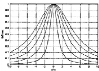
[image:3.595.246.346.402.474.2](3) normalization curve characteristics of horizontal magnetic field intensityHx
Figure 4. NormalizedHx/Hxmaxcurves of different depths.
Fig. 4 is the normalization curve characteristic of Hx’s maximum value. It can be seen that the smaller the buried depth is, the steeper the curve is, and the greater the buried depth, and the smoother the curve is. The distance between the two points of (0.8) Max is equal to the buried depth
h, and the distance between the points of (0.5) semi-extreme is equal to 2 times the buried depthh.
No matter how deep the burial depth is, this formula is established. 3
The Detection Principle of Electromagnetic Method
The underground cable path detection system is generally composed of transmitter and receiver. A certain frequency AC signal is injected into the cable to be measured by transmitter. The current flows in the cable to be measured and a magnetic field is generated in the surrounding space. The magnetic field intensity isHKI/R. Among them, K is the field intensity coefficient, R is the distance
System Design
The Overall Design of the System
[image:4.595.250.342.197.276.2]The system is used to detect the magnetic field signal of the area where the cable is to be measured. According to the distribution of the received magnetic field signal, the received signal is processed and calculated, and then the position, current magnitude and buried depth of the cable are judged, and the position of the cable is displayed and recorded in real time. The receiver uses seven detection coils to receive the magnetic field signals generated by the cable under test. The structure of the seven detection coils is described as shown in Figure5: 6
Figure 5. Structure diagram.
Among the seven coils, the coils 1, 2, 3, 6 and 7 are located in the same vertical plane, and the coils 2, 3, 4 and 5 are located in the same horizontal plane. The functions of the seven coils in the receiver are as follows:
The function of No. 1 coil: on the one hand, it detects the signal strength in peak mode, on the other hand, it works with No. 6 coil to detect the current intensity in the cable and the buried depth of the cable. The function of No. 2 coil and No. 3 coil: on the one hand, the position of cable buried in peak mode is judged, on the other hand, the direction of compass is judged by working with No. 4, No. 5 and No. 6 coil in valley mode. The function of No. 4 coil and No. 5 coil: work with No. 2, No. 3, No. 6 coil in valley mode to judge the compass direction. No. 6 coil action: on the one hand it work with No. 1 coil to detect the current intensity in the cable and cable buried depth, on the other hand, in the valley mode to determine the compass direction. The role of coil No. 7 is to detect the intensity of the signal in valley mode.
Selection and Design of Key Components
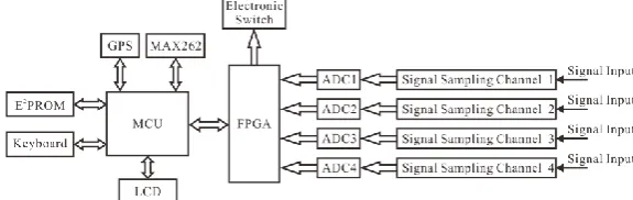
The system is mainly designed and implemented by single chip microcomputer and FPGA. The hardware circuit of the system is mainly composed of four parts, namely the power supply circuit, signal acquisition channel circuit, FPGA signal processing circuit, single chip microcomputer control circuit. The design of the power module is the first step of the system design, which provides a reliable guarantee for the stability of other parts. The system has 4 channels of signal acquisition and they can share in peak mode and valley mode. Induction EMF is generated by detecting coil, and induction voltage is generated in coil. The voltage signal is amplified and filtered and then sent to A/D converter chip. The analog voltage signal is converted into digital signal. The digital signal is processed by FPGA, and the processed result is transmitted to MCU. The results of these processing are analyzed by single chip microcomputer, and the final results and data are stored and displayed to the user through the indicator. The overall hardware design block diagram of the detection system is shown in Figure 6, in which the MCU selects the AVR series chip ATmega64 and the FPGA selects the Cyclone II series chip EP2C5T144C8 from the Altera company.
[image:4.595.152.440.685.776.2]The function of the signal acquisition channel is to extract the effective detection signal and input it into the FPGA for processing and analysis after filtering and amplification. Therefore, the acquisition channel circuit must have good stability, high reliability and high sensitivity. The overall block diagram of signal acquisition channel is shown in Figure 7.
Figure 7. Overall block diagram of signal acquisition channel.
Underground cable path detection system can not only detect 50 Hz power cable in normal working conditions, but also detect the cable in the case of not working, so the system designs two detection channels. Channel 1 is in the normal operation of the cable, the transmitter signal is inconvenient to add to the cable and then a channel for detecting power frequency 50Hz signals is adopted. In this case, no adjacent cables are required, and the interference of the cables to be measured is very small. Channel 2 is to inject a certain frequency AC signal into the cable by transmitter when the cable is not working. It can detect the cable path by the inductive electromotive force generated by the detection coil, which is suitable for the circumstance of multiple cables. At this point, the switch S1 turns on channel 2, and the induced EMF signal generated on the detection coil passes through the passive 50Hz notch circuit and the active 50Hz notch circuit, attenuates and filters the larger 50Hz interference signal, and then extracts the desired frequency signal through the high-pass filter and the center frequency adjustable band-pass filter.
Conclusions and Prospects
Taking the underground cable as the research object, this paper deeply analyzes the cable path detection technology, uses the electromagnetic induction principle to judge the underground cable path through the interaction of multiple detection coils, and discusses the working principle of the cable path detection system and the composition and Realization of each functional module in detail. In the next phase, the project team will continue to carry out laboratory testing and field testing, and further improve the system operation, acquisition and demodulation methods to enhance the power performance indicators.
Acknowledgement
The science and technology project of Yunfu power supply .Guangdong power grid co., LTD. “Intelligent inspection of 10kV cable line and comprehensive risk assessment technology”. GDKJXM20162235 (035300KK51160001)
References
[1] Zhang Zhigang. Research on Intelligent Cable Fault Detection System. Shanghai: Shanghai Jiaotong University Postdoctoral Dissertation, 2012.8-21
[2] Zhang Hanchun, Huang Guojun. Analysis and exploration of electromagnetic field characteristics of Extra-deep underground pipelines. Progress in geophysics. 2006, 10, 21 (4). 1315.1318
[4] Gareau Jean L. Embedded Systems Programming. Protected Mode, Apri l, 2008.
[5] Xia Yuwen. Verilog Digital System Design Course. Beijing: Beijing University of Aeronautics and Astronautics Press, 2017.120.176