H a H
o0
0
-O~~C7
af
H
UNIVERSITY OF MICHIGAN
SHIPBUILDING SHORT COURSE
October 27-31, 1980
HULL PRODUCTION PLANNING
Y. Mikami
IHI Marine Technology, Inc.
H. Kurose
Ishikawajima-Harima Heavy Industries Co., Ltd. (IHI)
S 1 Yp= epartment of Naval Architecture
noon |
CONTENTS
Page
I. INTRODUCTION . . 1
II. OVERLAP OF HULL PRODUCTION PLANNING AND THE DESIGN PROCESS . . 2
2-1. The Role of Design. ...
2-2. Design Flow and Production Planning.
III. BASIC PRODUCTION PLANNING. . . . .. . . . 3-1. Key Events Schedule.... . . .... 3-2. Building Method.. .. ... .... 3-3. Manhours Plan.. . ... . . IV. PRODUCTION SCHEDULING-... .
4-1. Master Scheduling.... . . . . . . 4-1-1. Erection Master Schedule. . .
4-1-2. Assembly Master Schedule. . .
4-2. Sub-Scheduling for Each Sub-Stage. .
V. DETAILED PRODUCTION PLANNING.. . ....
5-1. Fabrication Stage... . . . . . 5-2. Sub-Assembly Stage... ... 5-3. Assembly Stage... . . . . . 5-4. Erection Stage... . . . VI. PRODUCTION CONTROL. . . . . . . .
6-1. Control Parameters... . .. ... . . 6-2. Control Graphs for Hull Construction
" 2
" " 2 . .5
. . . 5
. 5
. .7
. .8
. .8
. 8
15
. . . 1
. . . 2
. . . 22 ...
. 22
. 32
. .. . . 32 .
UNT
RI
I. INTRODUCTION
The purpose of this paper is to introduce the logic and principles of
hull production planning applied in the Japanese shipbuilding industry.
The function of hull production in a shipyard is to construct a hull
structure consisting of numerous steel pieces to achieve the following
objectives:
- To maintain the ship's expected performance.
- To maintain high accuracy.
- To maintain the planned schedule.
- To maintain expected productivity.
In order to accomplish these functions many techniques have been developed
and are being continously improved.
It is difficult to give a full explanation in a limited time, but the
concept of the whole hull production planning process will be introduced by
II. OVERLAP OF HULL PRODUCTION PLANNING AND THE DESIGN PROCESS
It is well known that total production manhour requirements are greatly influenced by the ship's design. In other words, from the productivity view-point, the results are affected by production's involvement in the design. Accordingly, hull planning is started simultaneously with commencement of design.
2-1. THE ROLE OF DESIGN
From the viewpoint of design processes and their roles, design is classi-fied into the following categories:
Step 1: Basic Design. The basic design process is concerned with per-formance requirements, so it includes the development of basic guidance for key plans which will be undertaken at the next step.
Step 2: Key Plans. This design process is concerned with performance requirements as they are broken down into systems, predicated on the basic design of Step 1. Therefore, the main purpose of key plans is to obtain approval from the buyer and/or regulatory bodies. Also, key plans serve as guidelines for the development of yard plans in the next step.' So, produc-tion's basic planning is developed from key plans. Briefly, key plans are oriented towards "what vessel is to be built."
Step 3: Yard Plans. This design process is concerned with production as it pertains to the work order. So, yard plans are oriented towards "how to build the vessel." Accordingly, all production's intentions revolve
around yard plans. From this point of view, success or failure in production will be the result of the yard plan itself.
2-2. DESIGN FLOW AND PRODUCTION PLANNING
As mentioned above, production planning joins with the design process in order to involve production's objectives with those of the designer. Figure 1 shows an example of the relationship between design and production planning.
-2-m
V. r I r
1 .j. f IcI i 4 4; M
1R .
"
w t
it *1. 2e Y ,._ 3
v M
Jib
r = C i i
i
I
t
1 t
i
1rr
o 2
Q QI
.041
2 V
C
t E~
a
171
too
jrso mmmmlm
i
Z
cut,
! - i- 1 I i_ i 1 _
l
L-Z
. .wv. t .a 1 Li. 44
z 1
-- L' --- - - - -- f
-I I I
-. V
~
j;~ *jTICAs shown in this chart, there are many production activities involved in
the processes from basic design to yard plans as indicated by arrows on the
chart.
From the design point of view, the first consideration is to avoid
sac-rifice of the vessel's performance due to production requirements. Therefore,
a good design should be compatible with both performance and productivity.
-4-III. BASIC PRODUCTION PLANNING
3-1. KEY EVENTS SCHEDULE
Based on the delivery date determined by the Head office, the shipyard
General Manager decides the "Key Events" for each ship, based upon such
engineering data as the "Total Throughput Plan," "Total Manning Plan," "Total
Design Schedule," "Major Material Delivery Schedule," and "Building Method,".
etc.
The "Key Events Schedule" is the prevailing top-level schedule for the
production of a particular ship. All subsequent schedules and detail
pro-duction plans are developed based on the events determined by this schedule.
The most significant factor in this regard is to establish a realistic
schedule and to maintain this schedule precisely. In general, revision of
this schedule is not acceptable except in an emergency. An example of the
Key Events Schedule is shown in Figure 2.
3-2. BUILDING METHOD
The basic building method is determined prior to the development of key
plans by the design department because all hull key plans are dependent on
the position of erection joints. Also, all detailed engineering for
produc-tion is based on the requirements of a specific building method.
In this respect, the following items are determined as a basic strategy:
. Midship sizing & joining plan.
- Hull blocking.
. Erection method including added material.
- Erection master schedule.
Process plan.
" On-block outfitting method.
On the basis of preliminary key plans and shipbuilding plans, hull
struc-ture blocking plans are developed through discussions between production and
design departments at a joint meeting to determine preliminary and/or formal
hull blocking. Subsequently, the agreed-upon plans are included in formal
- --
f--1 1 U-1 I I I c7 f. R\
-~
t v
i
.
k _
r-I- T -. 1
3"-e6 pt- 1 1 \1 x
- .- 4-1-b - 4 'N
. I 1 1 1 '
F%
-_
_f.i
i
i
i
IIXLIIN
1TT XI
--
i-
j r .17 - fL ,
1 t I ! ! ji I 3 l s ! i Lam.. L4. IC 1i
_...._r - -.- - -
-_ -4-T_ _ _
.-No--
-4.)
'a1,
4, U
u,4
-p4
" f
t
i
1
.,
.
" -; .
T
A V
f
1 "
- : a "
k- X
2
. . .N.
.
.1 A
ammomme
Now-t D " y i .6 s i f r
mmogm.
r. i :
=won
I GOW
. " f ! i
-41 LL
1 . " ,
to
r
" " 1 1 , 1 j r 1 T
.. _ -1 1 _ _
-~a
Fl ? fE\"VAL .V'.
4 1 ., I
s-
___~i
A44~;i
f -i -- I'I I t .I
-
~
--I
lr-i = !. ,L
-s }
Q~
*
C
4--'.4 -- [ pa
L", "\ t r
i i i " " . - - -1 L w r v
r4a "
I Cal
r
-L '49F
.
r
- - t- - j-V. m1 ummV w. 01 Al N-__________________________y .. J
4-o Cos a aa
a,@1 @2 o . o 0 @2
0. 01cis o a:Qo o"
Os { - . "!
} ;
-cognizant shipyard functions, the ship's buyer, and the classification soci-ety, for their approval..
3-3. MANHOURS PLAN
The basic manhours plan is determined prior to development of detailed
plans. The basic manhours plan is derived from past data and modified to
meet the ship's specifications. It shows budgeted manhours for each
produc-tion stage, such as mold loft, fabricaproduc-tion, assembly, and erecproduc-tion by using
IV. PRODUCTION SCHEDULING
The hull construction schedule is the primary schedule in ship construc-tion. Accurate schedules greatly affect productivity, punctuality in ship's delivery, and the cost of production. For these reasons, the hull construc-tion schedule is carefully developed, taking into consideraconstruc-tion all aspects
of hull planning including on-block outfitting and on-board outfitting. This chapter addresses how the production master and sub-schedules are developed
from the yard's shipbuilding master schedule. The basic production process for production scheduling is shown in Figure 3.
4-1. MASTER SCHEDULING
Two master schedules are prepared for hull construction, i.e., erection
and assembly schedules.
4-1-1. Erection Master Schedule
This master schedule forms the basis for developing the assembly master schedule, and much of other sub-scheduling that comes up in each production area. The erection master schedule is constructed from the block arrangement
plan including the block erection sequence. In formulating this schedule,
the following determinations are made and confirmed:
(1) Milestones are determined in accordance with the key events schedule, such as keel-laying, shaft sighting, completion
date of the erection of the main hull structure, and launching. (2) Block erection intervals are determined, taking into account
shipwrightwork, fitting, welding, and on-board outfitting. (3) Finally, the smoothness of the erection process is checked
by means of erection weight curves.
Figure 4 shows an example of an erection master schedule.
-8--. 4 a
0@@-w 040 a-" 4
00
o cca
rf0 a 4m
0
~~4I
0 40
0
_ OA
C C "44
m tr m 1."
43-10 0
m° a &&-4 mrr o
p I jM ii +"4.)
3 .H !
A 1 A-
pO+C 0= 70 vm" 0'.s
O
v-A GOO
do-- t OE
~
f r
'j~
~
W*:(2~
SAM
0. 4J
r4.
-,
fii~
-. ,r~j
*
i w .-v:
4--i
M
"Ic
GOD
doo,
" r +
...
MId
rr
OWN 4
7-7.
now I
yj 1 ! "
...
f ew
-004
nzwo
i
I red limb W"O
don '
r M& 4-16
lamp fb
4 0
1 t t . { 1 1 . r r 1
r i OF
die.
OR i 1 i . f IV
- - . Em Ulp -0
&OW !Ee
1
11
"
-4 *0.*AD
4-1-2. Assembly Master Schedule
The assembly master schedule is made for each ship/block/assembly
area/date, on the basis of hull blocking plans, the block erection sequence,
and the erection dates on the erection master schedule.
The important considerations for determining the dates on the assembly
master schedule are:
(1) Assembly area availability for block assembly.
(2) Leveling requirements for each block in each assembly area.
(3) Manhour requirements for each assembly block and/or all blocks
in process for manpower planning.
(4) Outfitting and painting requirements for each block.
The assembly master schedule is prepared for a period of six months to
one year, with modifications to meet up-to-date conditions. Figure 5 shows
an example of an assembly master schedule.
4-2. SUB-SCHEDULING FOR EACH SUB-STAGE
A great variety of Sub-Schedules are prepared for each stage and
sub-stage of the production process. These sub-schedules are all based directly
on the assembly master schedule.
Considerations taken into account in preparing these schedules are:
(1) Part classification to maintain optimum and continuous production
flow.
(2) Times between fabrication, sub-assembly, and assembly operations.
(3) Limits of storage or buffer areas.
(4) Manpower work load leveling and smoothing.
s
It
I I I I I I I II - 1-1 1*.1 1 !I II Il'~f I I I I I I IIIIz
" I I,^ 1
!i :l
I
I
J
I
IIIIIII1 111I
,,° =
I I a
'
I
~
'ja; 2 1 I
I
I I I I
tIS
1.
':I
~
1
1:: ____II__II__?I I7
1
: *cl mm m... I mImIuIm. V
I
I II J1 I's I I I f I V I II
I
d 2 la I~i I II 1 11 1 T1T1Is' Q a 7 I III I I I I 11111
[
S
I I I
iI¢im1!
I I
I I
I .I
_______I !1
1 1 1 1 1I
.iIIIIIIIIId
~I
° I 11m..ImIImImIImmImlmmIImIIm 1 I i I
I I I I
I I___ __ __;
.
IIi
L
ImImImLL L
=mi
I
j-1
Lm4;III
I miIIJim0
L W mmiI..mmm AlammmmImmIm..immm-il
II
I I III I I
I
I I Im-m .-.- I-T. h I I I ! I I I " I . . _ I I I mmmmumIm
I i II; 2
-11=
I I
I
III > I I
II
L.I j~III
a
'- I[
IW.
i i
l .It.I
IImI I ImmmmIm I Iim" a
' I
I
I
II
I
I
C
I
fHdI1111
_______
a;
II
I "II mm I" Im=11I ImI _____ I I I ITILLLL
T' IlII11111i
m
l.IlK ;
_______I
- II il a
11 1
t1 1
Isla III 41 I I I I mumIImuI i ! f I I I f I I I I I I I I I I _____I
__ yI
~
I
I I _Types of sub-schedule of each stage are listed below;
(1) Fabrication Stage: mold loft, marking and cutting (skin plates),
marking and cutting (parts and pieces), and bending.
(2) Sub-Assembly Stage: ordinary, duct, and framing.
(3) Assembly Stage: flat block, semi-flat block, curved block, cubic
block, grand assembly block.
(4) Erection Stage.
For example, from among these schedules, the fabrication schedule is
1A
4 . E
0 N
I%
V. DETAILED PRODUCTION PLANNING
At each stage, from fabrication to erection, the stage plans are prepared for the workers of each stage in order to produce accurate products with high
productivity. These plans are developed from basic technical documents, such
as yard plans, mold loft plans, basic production plans and so on. The stage
plan of each stage shows only necessary information for that particular stage
as details are obtained from the basic documents.
The types of stage plans and their outlines are as follows.
5-1. FABRICATION STAGE
(1) Cutting Plans. The purpose of these plans is to prescribe the
marking and cutting of plates and shapes. Figure 7 shows an
example for plate.
(2) Steel Material Allocating Lists. These lists are issued with the
cutting plans, and are also used as steel material issue orders
for the fabrication workers, a reference for E.P.M. and manual
marking and cutting. Figure 8 shows an example.
(3) Size Lists. These lists are included in cutting plans to designate
marking of flat bars, face plates, and/or longitudinals. These
materials are itemized in the list for each block/process lane.
Figure 9 shows an example for flat bars.
(4) Bending Plans for Plates. Bending plans for plate bending provide
instructions for each plate in full size for utilization of universal
jigs. Figure 10 shows a 1/10th scale plan produced by the Automatic Drafter. The full size plans are made at the mold loft by projecting
the 1/10th scale film.
(5) Bending Plans for Shapes. Figure 11 shows an example. As shown in
this figure, the bending of the shapes is performed by straightening
the curved line.
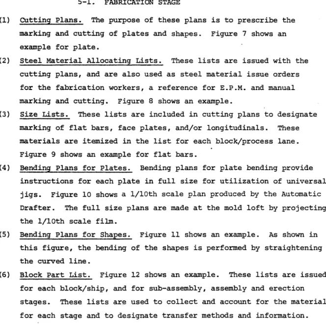
(6) Block Part List. Figure 12 shows an example. These lists are issued
for each block/ship, and for sub-assembly, assembly and erection
stages. These lists are used to collect and account for the material
~l.
w
i
44)
i" O
s
M
N~p~
..-
~43
PL " i
-I
£F
wmpqp41w Or
7rwrm.
<
- N
M R
' N
4
aMC ' }'; .. .,
.. ..
r M w
LOU
r-4
.6-I
'-4
U4J '1
U
co -4
r4
U..
. 'r
~I1
-
l
C.vUL
M
-WI
.y
a.
w
r
"1
N
o I
-____.1--"--U,..:
4wSo w
U- -aW
4 1
oI
Wz
1
~
v JN
I
I
~i
..o
I
i
U
HW I'I
-wo
I
j M .J
ww'
1.jn
Hi.n
{
.
CLa.
U
-J
Sm
i
l
01
=3
vi
.)
N
4I-.
____ =1 = r-,--5m:r
II II 1
11fi
w . N ca 96 ii. cn Lar W c
I
T
a C ~p. 2. = C 00o 0* A ^0'mb ahr-2
!1 " 'm ID 14 MI !Y Nt Nt rI7-9
Cw "W
Cmm
C
I , U.Z
r'
m-34J
"o 0" I,' I Id04U
4 0 044 -r4 %NIP w.
71
k r r0o
y i N Q 10m I'
N I
a-3
.! .1OC HYG. P~
# 7J
~Th
tiY,
- Y - I - -
~-'--:--i-~-I ~-'--:--i-~-I
* I;.r
-
T
-j-'-*~*-
-I
- is.... - .. insm..inIinl - -~
*-4-1- -
I
-I
-r
* - - -
f
- i mm -. - - I~r"1F/.f~4..
IsIctI&
jJU~QM&) 3.t3P ~7"
SCKw5lom
AT
(us-r_.TONP
'a
_ _Cww
.
pa
~I
S
-
QJ
gs%
VA
~WC"
__
L.ikan5~m- 3a1fmsam,,, iornsusiw
C.o,
L"M 321"t UL L40DIYMZONi'Tt5.S
~W
DP
mmAd OA OO
~'S
0
.L a0F
HE-Vs5-2. SUB-ASSENB.LY STAGE
(1) Sub-Assembly Plans. Figure 13 shows an example. These plans are
prepared for each sub-assembly unit and show- the instructions such
as material list, weight, weld length, significant features and so
on.
5-3. ASSEMBLY STAGE
(1) Panel Marking Plans. Figure 14 shows an example. These plans are
utilized for panel marking after completion of the panels.
(2) Fitting Plans. Figure 15 shows an example. These plans are
uti-lized for distribution of materials for fitting and welding.
(3) Size List for Assembly Jig. Figure 16 shows an example. These
plans are produced by the computer for the curved jig assembly
system. These plans show the height of each fixed jig, the
loca-tion of each plate and the degree of frame slant.
(4) Lifting Plans. Figure 17 shows an example. These plans are
uti-lized for preparation of block erection. These plans show the
arrangement of lifting pieces and temporary pieces for erection
work.
5-4. ERECTION STAGE
(1) Shipwright Dimension Plans. These plans show the position of each
block during erection. The breadth and height of each frame are
shown to assure accurate block erection. These plans are made by
a computerized system. Figure 18 is an example of the computer
output.
(2) Shipwright Instruction Plans. Figure 19 shows an example. These
plans are utilized for shipwright work and the following items are
- DetAils of the shipwright process.
-easuring points for accuracy, and tolerance limits. " The person responsible for accuracy.
(3) Welding Process Instruction Plans. These preliminary instructions are determined approximately five months before keel-laying. The
principal aim of these instructions is to specify automatic and/or
semi-automatic welding processes, and bevel data for each hull
part. At the same time, working instructions are developed for
each welding process, together with instructions for required preparation and correction information.
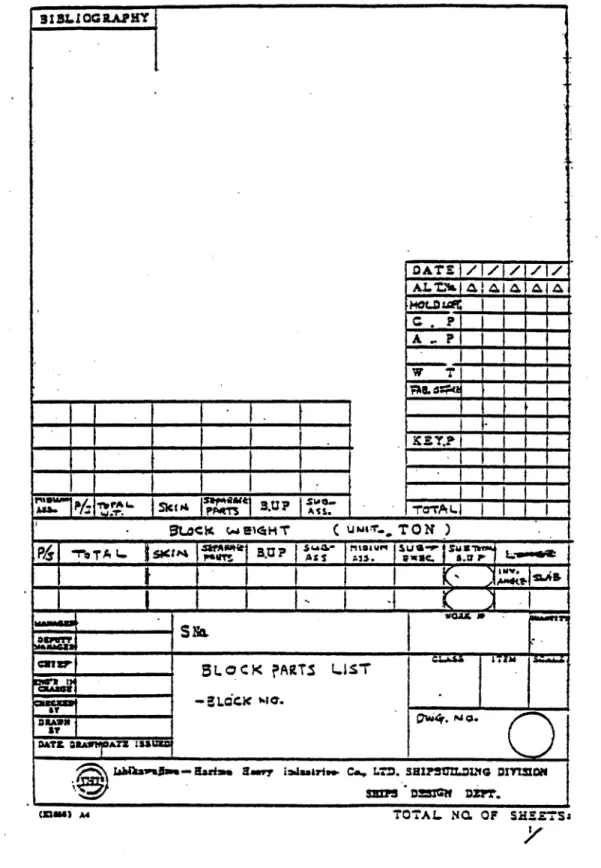
(4) Scaffolding Plans. These plans are developed based on the scaf-folding arrangement plan prepared at the basic production planning stage. Figure 20 shows an example. Welded pieces for support of scaffolding are fitted at the proper stage such as sub-assembly or assembly.
-23-E4
f
ii
' i '
1
'
r",
rf
i
_ _ _ _ _ _ _ _ _ll~L(
z6
.6vj
r+'
z
i;t
-
h
_rOj
41 .d07= ... 1
uH
y > W.+ 2t
fI
M .! 4c . .6 54 ZV .. _1 0 (I,Al l~
.IL
q1 t s",
n- :41
2
'L1
r-4 Cz4 Hi f4 "' t' fl tiM" /!1/ "
""
44
4, h.
Alb Ift m
IL op L L 40
a .
."
is
" r
lop
;
1 M
API i I i I i ' s4.
41"
i. If","t N
4 by
Z
r
i'
_
i r"
4 .1.=Y w .
h
M
Monh--M1
l
S. . ,.,
MON"
" .. . r r " - - --- " ---- y-- ' .
a i
v .
oil
'f#
* - b
1 0,0, 1 illt. I I
'if
6-!
vnr
S i y
.t'4
-I-i .\
fi "_ -
-
-~..-I A
It"
11!
.4
;4.
t 9 0 14
= i - 4p
I it
:i , "
's 4
r
t "
I'
r
Ac 1j #T
i
I +
C' II
0 s
". ti "t
do
w
r
-I"
A4
i --T+ i i - l i s NA __ _ _ i__
-s
t.
i
1
Z'I
!r
1j
'4' 41W woo r F' 'pi t A
ur ,e.r"' 112s , .''2 ._tsa s
odes
9 h - S ~ - - -
O!
' s r
"
V "
y.
r
l
Ic
"z
'I S
' '0
'K
c-.'
; 4 >'oil31
4ww
r.I*,!
I
K ;
i-I
#
I
, 1 * mo
r
.
A
I.
______ I
' '
- I II p
3a t W i oil 1 " 1.
( * .q.
..
S-I
I. I i
Mari cojki, . 1 Ef~
~L44KL
I.' CI.A~I
ILJL~iZUY
QjI
CA I
son 0
zom
=
=L
zM
M" *+ t a" i a "
-
OIQ
*
i
*Ja1
ai
c
w~
N
1000.
1197700 GS-n
I
a IYrga
11 2 (J. C IL=o
z-0fTJTWT7I
0,) .r4 Q4 *4 w41"' P
_ Lo
m-U
'm c
r.. x
_ 1 r
...-aa
044
" - ' V1
-. on.
J 1 fI v-l . 1v I
EME
'I'I+4 I I 4a
-617
- -- ,a- '
* L
::;' f
.,,
_. .
-:.
;;
jf
4.) 4-4
.a.
H
Of
ti
IIt t ti:t II 1
1 ! t I t 1
1 t 1 1sa I00
y 1f
1 "
1 I' MN ;I I
" O {;I vii.Z 11. 1 .wll
:1
1 N I 1 w- I' T 11 1 1. e Q 1 1 V V: / s:el f '~
*4..21 C a ,
%sm
s
M1 ' " 1 r . ,w" U1 1 111 ! 4":i }1a. W1 / O 1a' 111
" N ,I fV 1 1. ' 1 MW, 0 MO :( .1I 1
*O ' i 1 J! 1. . 1 1 1' t! a
f! ea 1 t I ISI I'1 S
i 1 O w" I A" 1 P 1 . 1 I /f
gi.4
/
t
M "A" 1 "V 1m"""""i 1 ' 1tII 1H! "' /r "Ve 1 N M S ' 1S!1 1 ft *f"
an of
..
: .we !. men s-" " U 1 " W~Is " " " 1.S 1I I I 1
w19 I *w ma "9" 15 1. +"S w 141I1SitftII
1 t /1. a
r- 1 A l- ra . 4 r I 3t. I t " I1.
1a1 w 1I Ni "
~
:
~
voas
"a q 1 8. 31 " " 1 "
" 1 t- t t* +aA ! a a
NIf f 1 5 1 " 11
tI 5 .4 .4 i
"1S %o 1f 11H+
a I
1*f1
.f1
11
rr
t
H
"f
*apa
_ _ _ _ *
'" ' 7
J
~.
I- -'1 U I INOW
* ;.4=N- w
_6
4:A
"
1) Y
_
r
)I:.
~_/_-t
.. r -r j
7U-'m.. -da
'.~ &~t 4
~ ~-~sto
7~~
t-~1.0
a74 ga aC
SNQ
- ..
'
I-4-im-f tz R q 0
.1 :--tj
m
I
1-)01-
oil-f
~
."2//L(:27
POP. mo
Et
~ V
_
I-196
/
"1 :
VI. PRODUCTION CONTROL
6-1. CONTROL PARAMETERS
On the basis of the correlation between work volume and manhours, proper
parameters are used at each stage and process to forecast and measure work
progress. Figure 21 is shown as an example.
6-2. CONTROL GRAPHS FOR HULL CONSTRUCTION
Control graphs for hull construction are prepared for each stage and
process. Forecasts made during each planning activity are measured against
actual work progress at the completion of each scheduled completion event.
This comparison then allows adjustment of manning and/or schedules, if
required.
The kinds of control graphs are as follows:
(a) W.T. advance curve between fabrication, assembly and erection
(day base), Figure 22.
(b) Hull total M.H. curve (erected weight base), Figure 23.
Sc) Design and mold loft advance curve (day base), Figure 24.
(d) Mold loft M.H. curve (day base), Figure 25.
(e) Fabrication M.H. curve (day base), Figure 26.
(f) Fabrication M.H. curve (W.T. base), Figure 27.
(g) Sub-assembly M.H. curve (W.T. base), Figure 28.
(h) Sub-assembly M.H. curve (W.L. base), Figure 29.
(i) Assembly W.T. curve (day base), Figure 30.
(j) Assembly W.L. curve (day base), Figure 31.
(k) Assembly total M.H. curve (W.T. base), Figure 32.
(1) Assembly total M.H. curve (W.L. base), Figure 33.
(m) Assembly welder M.H. curve (W.L. base), Figure 34.
(n) Assembly fitter M.H. curve (W.L. base), Figure 35.
(o) Advance curve between fitting and welding of erection (day base),
Figure 36.
(p) Erection W.T. curve (day base), Figure 37.
(r)} Erection total
M.H..
curve (W. L. base), Figure39.
Cs) Erection fitterM.R.
curve (WL., base) , Figure40..
(t) Erection welder
M.Ii.
curve '(W.L.'base),
Figure 41.-33-SHOiP "
j
AG WORKING IPARAMEPM 'NUMB r o 1 znz
~.Cox
JCRVATUR~E C1NGCN
CECTON
MME CTNSANGLE CUTTIhNG _______
S DECK
HOUSE
C O17 NG'SB T T -'
#LATE sEN tNG =rof cT a i~
mSMALL
PIEC' BENDING o= ojecePITNG
N WELD NG'w .L60.
IMA rtAL SORTINGTNNGg
SUB' TOT LT~jNAE_
N1,
C
SHOT BLASTING NUIM5ER of o 1a:
CRANC.
SrVO ! t 1NP.! N!IMO rn;sr
PILATE JOINING AWL
~
ITNG W .L .I
~
WELING W .}.
- - MaTAI Tt-'ANL NG TONNAGE o 6 o f TiT NG.!
r - it' j IIf
~
m~CAF=
ONG TONNAGECIANE
ih~
.
"" 9*- O M w
a 3s 4
* ia
f
«.. * 4:Co0
P4-Z I
C)
s4
sb l/
a)
4
U
01 0
1H
OOg
R
ti
_
f w S
5%
% V c
'r m'
5%b
1
9Q____[________________
"i
Q3~
U)
0
0
a
a
N~
t
i 1
t t. t' t
I
r-j
fem.
j
i.
r
C h
f 1
.V
"1t
s
Z
r
+ N
A
. 1
IC
s
z
NI
11 p.
S2 -r4
02
0
4-4
0
0-4
rz4
1 I 0 i h 1 t i I
F -- -- -- - _ ..
v I F ; . ;-.r
' 3
ti
} .
1
-t
r i - "'?
Z
f
i
f .
P d ..r+ . . a.. t i ? . 0 C r W
. 1 .
i l 1
.1 a S . 0 0 4J U) 10 to .r4
1w
'S.14
Z"1"
i
s
3
GRIMM
i=
ON
3 a)
U) '44
0
.4-(U
CT4
I
t
_
.
i
i
}
1
1
I
i
f--I
4
3
"
.9
3
HU
Q 0
4.,
N N
0
M
N
(1
aU
HT SQ
aJ
110
Jv92 o\
r
t
I
t
r4)
0'j
NU
a
rH
OU
U,
rU,
NU
0
'u
N
. .
1 i
I i 1 j i i 1'
e.
t
s.p J-, r r I PI b39 i
I1 VI 04
'I?
U r____I_____E
c1.
INCt_________Li_______
7mj-
r.
<
4
o2 01 4 ' 3 02 en .,4I 44 I r i 0 14 1% C h-
! f 1.
i
1
E
I
t 1
1
1
i
1f
f
ra
Z*i
1.3
J.
Z
t7 4
r4
m2
.C:
ci >9
H
4.1
go
C,,
.,q w
0
a
a
H
F. 1
4c
)0P
I
".1
f f
r s'
Z r
..
4r+i
44
N 2
,
! \ IL 1
A
I
T
43
-4
02
r1)
4-J
0
4J
10
0
G4
i
s°1
,v
r
. .
_ ,
w
"o
l
1
I
{n
a
4
4
10
s-0
4M
fr
w3
4J
i-'-{
Ha
a
0%
3
m
Oi
3I
Ss
w4
A
'9's
jC
II
I
3
u)
.
4.)
4Im
.,
t
3
f
1
.o
J
km
**
~'
Z
~1-4J
.J
-P.4 4-4
3
4
CU
'0
i)
5Z4
ml
U
0
0
4J4 U 4)
0
i
"4
rI
1
z
4c
.6
tWA-4---t
' I
i
' '
,
4
.
j e
.f t
s t
aIti
1
-I.
__MHHH
1
4IJ
'U
U)
U
U "
0
id
413
0
.4
4J)
U. Ni
WI
CO
w'-I
tp
'J
"
.i
r
"*
, y
1 -* J.
z
_ t
i
L
i
I
ra
3)
v)
O'
0
4J
0
41)
U
A . wz
!q.
0'
41
'0
41 U) WI J,
l CD 0r
i L
w
y
yr' '
1
1
" 1 ?n
alp,
i
uw
41
3
y)
a m
U)
U)
t3
4
w
I
3 9015 07553 7020