The development of an active implantable neural
probe system for chronic use
A thesis submitted to the University of Dublin, Trinity College
In partial fulfilment of the requirements for the degree of Doctor of
Philosophy
Laura Constance Frey
Supervised by Dr. Kevin O’Kelly
Trinity College Dublin, May 2017
i
Declaration
I declare that this thesis has not been submitted as an exercise for a degree at this or any other university and it is entirely my own work.
I agree to deposit this thesis in the University’s open access institutional repository or allow the library to do so on my behalf, subject to Irish Copyright Legislation and Trinity College Library conditions of use and acknowledgement.
Signed,
ii
Abstract
The alleviation of symptoms of debilitating neural conditions via neural probes is an
increasingly important area of research. However, the effectiveness of these probes
decreases over time due to the formation of a glial scar around them. In order to design
probes that can function long-term, this research study developed two main approaches
to reduce the inflammatory response: one focusing on reducing the inflammatory
response around the probe via a coating with controllable surface topography and drug
delivery capabilities and the other on designing a neural probe utilising cooling as an
alternative therapy to electrical stimulation to reduce the inflammatory response at the
functioning tip.
In order to assess material topographical effects in vitro, PC12 cells, primary neuronal
cells from rats and human astrocytes were plated onto hydroxyapatite (HA) discs of
various degrees of roughness. A method of encapsulating astrocytes in a gelatin
methacryloyl (GelMA) hydrogel was also devised in order to allow studies of over a week
to be carried out. HA was found to be non-cytotoxic, with PC12 and primary neuronal
cells surviving and attaching to the moderately rough surface best, implying there is an
optimum roughness to promote neuronal survival. This was further corroborated by
astrocytes, as they exhibited the highest expression of inflammatory cytokines TNF-α
and IL-6 when plated on the very rough surfaces.
As topographical control alone was found to be insufficient to significantly reduce the
inflammatory response, a drug eluting coating was also developed. This consisted of a
iii
factors to brain tissue long term. This system offered the added benefit of being able to
be inserted in its thin dry state before reswelling to provide anchorage against
micromotion. Diffusion tests showed the system could release cytokines over a 4 day
period from one infusion and could release small drugs with minimal burst release.
Repeated infusions of IL-4 upregulated anti-inflammatory M2 phenotype macrophages
and downregulated the expression of pro-inflammatory markers in astrocytes over a 3
week period.
An experimentally validated thermal model was created in Comsol® to assess
temperature profiles around a cooling probe in the human brain. This was linked with a
Peltier chip and heat sink model in order to create a tool allowing for the prediction of
Peltier and heat sink settings required to deliver a desired temperature at the probe tip.
A 4mm probe consisting of silver core coated with HA was suggested as the current best
method of ensuring therapeutic temperatures at the tip. This probe would also offer
mild cooling along the probe length to reduce glial activation and therefore the
formation of a glial scar.
These two strategies were initially proposed as complementary ideas, however, the
results of the investigations indicated that the cooling along the length of the cooling
probe and the potential to release anti-inflammatory factors preferentially at the
functioning tip of the probe resulted in an overlap in function between the two
strategies. They are therefore presented as two separate solutions – a novel cooling
probe or alternatively a coating system to increase the efficacy of current electrodes.
With further work, both of these probe designs have the potential in the future to be
iv
Acknowledgements
Firstly, a huge thank you to my supervisor Dr. Kevin O’Kelly for giving me this
opportunity. His guidance and support has been invaluable and I thank him for all the
time invested in helping me improve and advance my project and research skills.
I would also like to thank Prof. Ali Khademhosseini for hosting me in Harvard and for his
advice and support at all stages of the project. A special mention must go to my
inspirational mentor Dr. SuRyon Shin for her unwavering encouragement and guidance
and the drive and belief she instilled in me. A further thank you to Fulbright Ireland for
facilitating my time abroad and making sure my experience was the best it could be.
For their generous consultancy, thanks to Prof. Shane O’Mara and Prof. Kumlesh Dev for
teaching me about all things brain and Dr. Tony Robinson for his help, enthusiasm and
encouragement in heat transfer. The help I received in both universities was wide and
varied and I thank every team member, technician, collaborator and friend I met along
the way. To my friends in TCBE and the Khademhosseini lab, thank you for your kindness
and camaraderie – particularly to Jacob Mealy my partner in crime in Trinity and Julio
Aleman at Harvard, part time advice giver and counsellor, full time friend. A special
mention must also go to DUHAC for enriching my university experience, giving me some
of my best friends and saving my sanity at the track, particularly in final year.
Finally, my parents, my grandparents and my sister Alana, thank you for your
unwavering support and belief in me, not just in the past 4 years but in all 27. I wouldn’t
be where I am today without the love and guidance you give me and your patience and
v
“
Two roads diverged in a wood,
And I – I took the one less traveled by,
And that has made all the difference.”
vi
Contents
Declaration ... i
Abstract ... ii
Acknowledgements ... iv
List of Figures ... x
List of Tables ... xviii
List of Abbreviations ... xix
Presentations and Publications arising from this Study... xx
Presentations: ... xx
Publications: ... xxi
1 Introduction ... 1
2 Literature Review ... 5
Introduction ... 5
Neurobiology16 ... 5
Brain Cell Types and Functions ... 7
Electrode Design and Functionality ... 10
2.4.1 History of DBS ... 10
2.4.2 Current Electrode Design ... 11
2.4.3 Ideal Electrode User Requirements ... 13
2.4.4 Current Electrode Limitations ... 14
Problems with Design ... 15
Strategies to reduce Inflammatory Response ... 16
2.6.1 Coating Material ... 16
2.6.2 Flexible Probes ... 20
2.6.3 Topographical Control of Coating Surface ... 21
2.6.4 Size, Shape and Insertion ... 23
2.6.5 Drug Delivery ... 26
2.6.6 Neuronal Cell Regeneration ... 34
Alternative Therapeutic Strategies ... 37
2.7.1 Cooling Strategies ... 37
2.7.2 Cooling Probe Coating Design ... 41
vii
In vitro and in vivo Evaluation Strategies ... 49
2.8.1 Cell Types ... 49
2.8.2 In vivo methods ... 51
Conclusion – Emerging Research Questions ... 53
3 PC12 Cell, Primary Cortical Neuron and Astrocyte Response to Surface Topography of Coating Materials for Neural Probes ... 57
Introduction ... 57
Methods ... 60
3.2.1 HA Disc Manufacture ... 60
3.2.2 Cell Culture ... 60
3.2.3 Cell Plating ... 61
3.2.4 Metabolic Assays ... 61
3.2.5 GelMA Fabrication ... 62
3.2.6 Astrocyte Encapsulation ... 62
3.2.7 ELISA Assays ... 63
3.2.8 Statistical Analysis ... 63
Results ... 65
3.3.1 Disc Fabrication and Manipulation of Surface Roughness ... 65
3.3.2 PC12 Cell Study... 66
3.3.3 Cortical Neuronal Cell Study ... 67
3.3.4 Direct Astrocyte Culture ... 71
3.3.5 Astrocytes Encapsulated in Gels ... 73
Discussion ... 79
Conclusions ... 84
4 A Dual-layered Microfluidic Coating for Long-term Controlled In Situ Delivery of Multiple Anti-inflammatory Factors for Chronic Neural Applications ... 86
Introduction ... 86
Materials and Methods ... 90
4.2.1 Synthesis of Gelatin Methacryloyl (GelMA) ... 90
4.2.2 Agarose Fibres ... 90
4.2.3 GelMA Solutions ... 90
4.2.4 Fabrication of PDMS Membranes ... 90
4.2.5 Scaffold Fabrication ... 91
viii
4.2.7 Microscope Imaging ... 92
4.2.8 Nanodrop ... 92
4.2.9 Instron ... 92
4.2.10 Monocyte Culture and Encapsulation ... 92
4.2.11 Astrocyte Culture and Encapsulation ... 93
4.2.12 Chronic Cell Studies ... 93
4.2.13 Live/Dead Assay... 93
4.2.14 Immunostaining ... 94
4.2.15 ELISA Assays ... 94
4.2.16 Statistical Analysis ... 94
Results ... 95
4.3.1 Fabrication of Microchannels ... 95
4.3.2 Hydrogel Optimisation ... 98
4.3.3 PDMS Membrane Construction ... 100
4.3.4 Chip Development ... 102
4.3.5 Diffusion through the Scaffold ... 102
4.3.6 Brain Model Development ... 106
4.3.7 Chronic Studies: Monocyte Model ... 109
4.3.8 Chronic Studies: Astrocyte Model ... 111
Discussion ... 114
Conclusions ... 119
5 An experimentally validated Thermal Model for Cooling Neural Probes ... 121
Introduction ... 121
Methods ... 124
5.2.1 Probe Design... 124
5.2.2 Probe Comsol® Model ... 125
5.2.3 Thermoelectric Module and Heat Sink Design ... 126
5.2.4 HA Dipcoating ... 127
5.2.5 PDMS Coating ... 128
5.2.6 Brain Analogue ... 128
5.2.7 Scanning Electron Microscopy (SEM) ... 128
5.2.8 Experimental Validation ... 128
Results ... 130
ix
5.3.2 Probe Comsol® Model: Thickness Ratio ... 132
5.3.3 Peltier Chip Design ... 133
5.3.4 Experimental Validation ... 136
5.3.5 Analysis of Model Outputs: Cold Plate Insulation ... 141
5.3.6 Analysis of Model Outputs: Thickness to reach therapeutic Temperature ... 143
Discussion ... 147
Conclusions ... 152
6 Overall Discussion ... 155
7 Conclusions and Future Work ... 166
Conclusions ... 166
Limitations ... 172
Future Work ... 176
Bibliography ... 181
Appendices ... 195
Appendix A: ... 195
x
List of Figures
Figure 2.1. Diagram of the human brain1. 7
Figure 2.2. The differences between resting and activated microglia in the brain2. 9
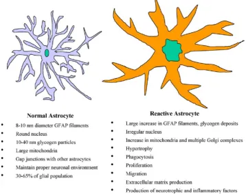
Figure 2.3. The differences between resting and activated astrocytes in the brain2. 9
Figure 2.4. Medtronic DBS electrode design3. 12
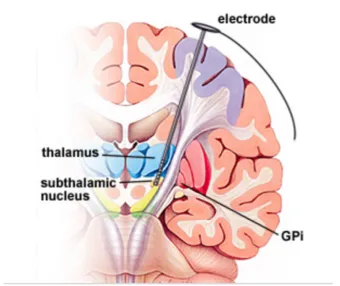
Figure 2.5. Cross-section of the brain showing DBS electrode placement in the sub
thalamic nucleus4. 12
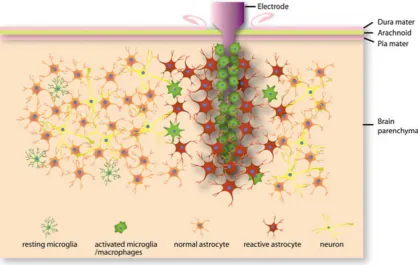
Figure 2.6. Schematic of cellular changes induced by electrode insertion into the brain,
resulting in glial scar formation and encapsulation of the electrode5. 16
Figure 3.1. Schematics showing the A) fabrication of HA scaffolds via pressing and
sintered before addition to the 24 well plate; B) encapsulation of cells in hydrogel. 63
Figure 3.2. SEM images of HA discs created at different pressures and temperatures to
produce different roughnesses.A) Hard pressed and sintered at 1350°C at 1000x; B)
light pressed and sintered at 1350°C at 1000x; C) Light pressed and sintered at 1200°C
at 1000x; D) Hard pressed and sintered at 1350°C at 6000x; E) light pressed and
sintered at 1350°C at 6000x; F) Light pressed and sintered at 1200°C at 6000x. 65
Figure 3.3. Measured metabolic activity of attached PC12 cells on 1350R, 1350S, 1200R
surfaces at Day 1, 4 and 7 showing 1350R with significantly the highest metabolic
xi
Figure 3.4. Measured metabolic activity of attached glial cells on 1350R, 1350S, 1200R
surfaces at Day 1, 4 and 7 showing 1350R with the highest ,metabolic activity at Day 7
(n=4). 68
Figure 3.5. Measured metabolic activity of attached cells on 1350R, 1350S, 1200R
surfaces at Day 1, 4 and 7 (n=4);A) Isolated primary cortical neurons (normalised to day
1); B) Isolated primary cortical neurons unnormalised (n=4). 69
Figure 3.6. Astrocytes cultured directly onto HA discs: Confocal images after 1 week
stained with DAPI (blue) and cell mask (red): A)1200R; B)1350R; C)1350S. 70
Figure 3.7. Pro-inflammatory markers released by astrocytes encapsulated in hydrogel
placed on top of HA discs after 1 week A) TNF-α release (n=4); B) IL-6 release (n=4). 71
Figure 3.8. Astrocytes cultured directly onto HA discs. Astrocyte metabolic activity over
one week using metabolic resazurin assay (n=4). 72
Figure 3.9. Confocal stacks of unsuccessful astrocyte models after 1 week of culture in a
5% GelMA hydrogel structure with varying % PI and UV radiation exposure. DAPI staining
(blue) for nuclei and Cell Mask 649 (red) for cell structure A) 20s UV 0.5% PI; B) 30s UV
0.5% PI; C) 40s UV 0.3% PI; D) 40s UV 0.5% PI. 74
Figure 3.10. Confocal stacks (200µm thick) of astrocyte model after 1 week of culture in
5% GelMA hydrogel structure with 0.3% PI and 30s UV radiation exposure. DAPI staining
xii
Figure 3.11. Astrocytes encapsulated in hydrogel on top of HA discs: Confocal
microscopy images after 1 week stained with DAPI (blue) and cell mask (red): A) 1200R;
B)1350R; C)1350S. 76
Figure 3.12. Pro-inflammatory markers released by astrocytes cultured in hydrogel on
top of HA discs after 1 week A) TNF-α release with the highest inflammation that of the
roughest surface 1200R (n=4); B) IL-6 release (n=4) with the highest inflammation that
of the roughest surface 1200R (n=4). 77
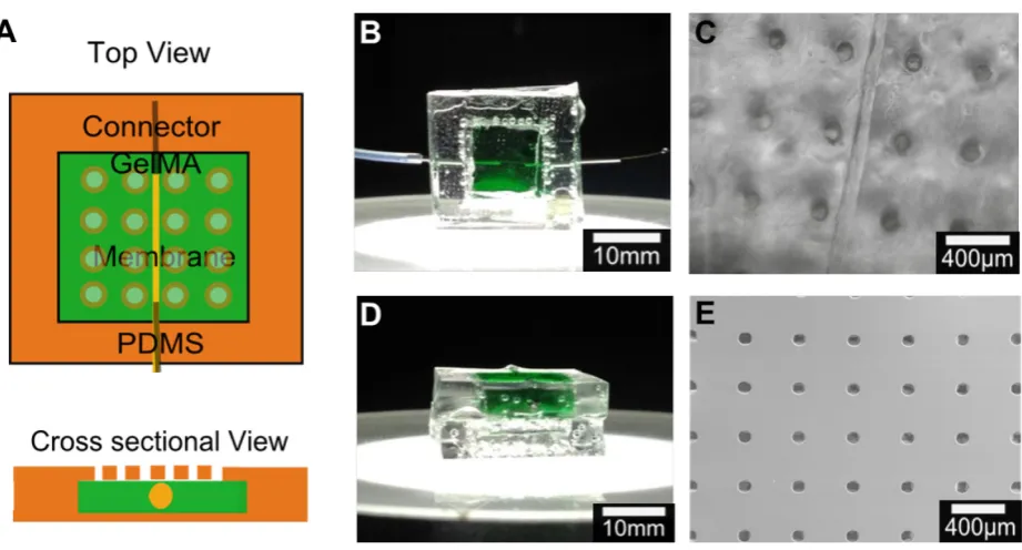
Figure 4.1. Construction of dual-layered microfluidic system and its concept. A)
Schematic diagram illustrating the concept of the transformation from dry insertion
state to drug delivering implantation state. B) Preparation procedure of microchannel in
GelMA hydrogel construct surrounded by microporous PDMS membrane. 94
Figure 4.2. Agarose microchannel optimisation. A) 250µm microchannel formed by
removal of 4% agarose fibre and successfully filled with dye; B) Cross-section of
microchannel post drying and reswelling stage showing shape formation and shrinkage.
95
Figure 4.3. Alternate sacrificial fibre formation strategies A) Bioprinted alginate fibre
exhibiting uneven nature; B) Hair showing uniform diameter. 96
Figure 4.4. Microchannel integrity in GelMA.A) Demonstration of microchannel failure
in weak GelMA gel; B) successfully filled looped microchannel. 97
Figure 4.5. Hydrogel optimisation. A) Compressive modulus of three different
concentrations of GelMA/PEG hydrogel composites (n=6). B) Reswelling profiles of three
xiii
Figure 4.6. SEM image showingGelMA/PEG porous structure. 99
Figure 4.7. PDMS Membrane formation. Microscope image showing open pores (dark)
and closed pits (light). 100
Figure 4.8. Construction of PDMS membrane and frame. Schematic demonstrating
addition of partially cured PDMS frame to membrane pre-curing. 101
Figure 4.9. Chip design optimisation. A) Schematic of chip design B) Top view of sample
chip with GelMA/PEG section stained green C) Top view of chip showing 100μm channel
and 100μm pores D) Cross sectional view of sample chip E) SEM image of PDMS
membrane with 100μm pores with 400μm spacing. 102
Figure 4.10. Diffusion profiles of FITC variants with different molecular weights through
chip system.A) Schematic of tests to show diffusion: optical set-up using microscope
images and quantification using nanodrop to measure diffusion into a PBS reservoir. B)
Optical images over time of FITC-Dextran (40kDa MW and 20kDa MW respectively) and
FITC isomer (389Da MW) showing effect of molecular weight on diffusion time. 103
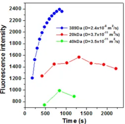
Figure 4.11. Diffusion profiles of FITC variants with different molecular weights through
chip system. Progression of fluorescent signal is measured at a fixed point as FITC
diffuses through hydrogel system to calculate diffusion co-efficient D. 104
Figure 4.12. Diffusion profiles of FITC variants with different molecular weights through
chip system (n=6). A) Quantity of FITC diffused through system at 24 hr time points
showing 40kDa FITC-Dextran has peak release after 48hrs B) Quantity of FITC of different
molecular weights diffused through system at 8hr time points as demonstrating steady
xiv
Figure 4.13. Mechanical properties of in vitro brain model. Compressive modulus of
monocytes encapsulated in 5% GelMA photocrosslinked with varying UV light durations
indicates 20s as optimum time for similar mechanical properties to brain (n=5). 107
Figure 4.14. Survival of monocyte cells encapsulated in 5% GelMA system as an in vitro
model for brain immune response.A) Monocytes stained using calcein (green) for live
cells and ethidium homodimer-1 (red) for dead cells showing minimal cell death during
procedure at day 0. B) Monocytes stained using calcein (green) for live cells and
ethidium homodimer-1 (red) for dead cells showing minimal cell death during procedure
at day 7. 107
Figure 4.15. Phenotype of monocytes after different drug delivery profiles through
hydrogel system. Immunostaining of CD206 (green) as an M2 macrophage, nuclei (blue),
and 27E10 (red) as an M1 macrophage at week 1 for profiles listed in Table 1 A) delivery
profile A; B) delivery profile B; C) delivery profile C; D) delivery profile D; E) delivery
profile E and for week 2 for F) delivery profile A; G) delivery profile B; H) delivery profile
C; I) delivery profile D; J) delivery profile E. 109
Figure 4.16. Quantification of macrophage survival and phenotype A) Surviving cell
count at weeks 1 and 2 determined by percentage DAPI staining evident B) Ratio of
M2/M1 differentiated macrophages for all delivery profiles at 1 and 2 weeks indicating
that repeated infusion of IL4 significantly increases the presence of pro-healing M2
macrophages. 110
Figure 4.17. Confocal stacks of astrocytes after 3 weeks of different drug delivery
xv
for cell structure A) delivery profile A, B) delivery profile B, C) delivery profile C, D)
delivery profile D, E) delivery profile. 111
Figure 4.18. Pro-inflammatory marker release from astrocytes after 3 weeks of different
drug delivery profiles through hydrogel system A) TNF-α at Week 1 and 3 B) IL-6 at Week
1 and 3 (n=4). 112
Figure 5.1. Design and components of a Peltier cooled neural probe, defining all
temperature differences to be used throughout this chapter. The probe consists of two
parts which will be referred to as core or insulation, probe refers to the combination of
the two. 123
Figure 5.2. Initial model dimensions in Comsol®. 125
Figure 5.3. Schematic of experimental setup for validation. 128
Figure 5.4. SEM Images of HA dipcoated coatings A) 2 coats of HA at 25x magnification;
B) 2 coats of HA at 100x magnification; C) 2 coats of HA at 600x magnification; D) 4 coats
of HA at 25x magnification; E) 4 coats of HA at 100x magnification; F) 4 coats of HA at
600x magnification. 130
Figure 5.5. Image of PDMS coated probesA) dipcoated; B) Diagonally wrapped partially
cured PDMS; C) Horizontally wrapped partially cured PDMS. 130
Figure 5.6. Influence of increasing thicknesses of silver cores between 0.5mm and
1.75mm on temperature profile along probe length. The lowest temperature at the tip
xvi
Figure 5.7. Influence of increasing insulation thicknesses on temperature radially for
core diameters of 0.5mm to 1.75mm. The added insulation for the 1.5mm silver core
results in better insulation along the probe length with a temperature difference
between the two models of 1.6°C at the midpoint vs only 0.6°C at probe tip. 132
Figure 5.8. Assessment of cold side temperature required to achieve various
temperature drops at the probe tip for core diameters of 0.5mm to 1.75mm. A
temperature drop of 4°C requires a TC of -10°C for a 1.5 or 1.75mm core. 133
Figure 5.9. Assessment of temperature difference across Peltier with varying current.
With a TC of -10 required, a ΔTTEC of approximately 40°C will be required which is within
the capabilities of this Peltier. 134
Figure 5.10. Assessment of heat sink resistance with varying current. A heat sink with
0.35-0.45K/W resistance is sufficient if operating at a current of 4A or above. 135
Figure 5.11. Experimental Set Up. 136
Figure 5.12. Peltier Current vs ΔTTEC predicted vs real results showing good prediction of
temperatures with some divergence of values at currents of 4A and higher. 137
Figure 5.13. Comsol® model of temperature at core vs 2mm away from the surface of
probe for initial temperatures of -10°C to 10°C shows a loss of up to 10°C radially at the
base of the probe. 138
Figure 5.14. Comsol® Model vs experimental results for temperatures 2mm from probe
xvii
Figure 5.15. Heat sink resistance as a function of voltage. Resistance decreases as
voltage increases and heat sink operates at 0.34-0.42K/W. Error bars represent the
standard deviation of the average of 5 trials. 140
Figure 5.16. Model comparison of temperature of brain surface temperature depending
on thicknesses of aerogel and polystyrene insulation with varying initial temperatures
showing a strong dependence of brain temperature on insulation thickness until
changes in thickness make negligible differences to brain temperature. This occurs at
1cm for polystyrene and 3mm for aerogel. 141
Figure 5.17. Temperature of probes along length with different total diameter but a
fixed core: insulation ratio of 3:1. This highlights the increasing differences in
performance between HA and PDMS as insulators with increasing thickness. 143
Figure 5.18. Temperature profiles of probe and brain tissue 2mm away probe along the
length of probes with different total geometries and ranges of probe:coating. A) 3:1 ratio
probe temperature; B) 3:1 ratio brain temperature; C) 1:1 ratio probe temperature; D)
1:1 ratio brain temperature; E) 2:3 ratio probe temperature; B) 2:3 ratio brain
xviii
List of Tables
Table 3.1. Table showing the gradient and standard deviations of the trend lines for each
roughness and cell type. 67
Table 3.2. Astrocyte model testing conditions varying % photoinitiator and duration of
UV radiation. 73
xix
List of Abbreviations
Ara-C Cytosine beta-D-arbinofuranoside BBB Blood Brain Barrier
BSA Bovine Serum Albumin ClO4 Perchlorate
CNS Central Nervous System CSF Cerebrospinal Fluid
DAPI 4, 6-diamidino-2-phenylindole DBS Deep Brain Stimulation DEX Dexamethasone DI De-ionised
DMEM Dulbecco’s Modified Eagle Medium ECM Extracellular Matrix
ECD Electrochemical Deposition EPD Electrophoretic Deposition FBS Fetal Bovine Serum FDA Food Drug Administration FEM Finite Element Method FITC Fluorescein isothiocyanate GelMA Gelatin methacryloyl GFAP Glial Fibrillary Acidic Protein HA Hydroxyapatite
IL-X Interleukin-X MW Molecular Weight NGF Nerve Growth Factor PAA Polyacrylic acid
PBS Phosphate Buffered Saline PDMS Polydimethylsiloxane
PEDOT Poly(ethylenedioxythiophene) PEG Polyethylene Glycol
PEG-PLA Polyethylene Glycol-Polylacticacid PFA Paraformaldehyde
PI Photoinitiator PLA Polylactic Acid
PLD Pulsed Laser Deposition PLGA Poly(lactic-co-glycolic) acid PMMA Poly(methyl methacrylate) PNS Peripheral Nervous System Ppy Polypyrole
pSS Polystyrene sulfonate pTS p-toluene sulfonate PU Polyurethane PVA Polyvinyl acid
RPMI Roswell Park Memorial Institute SD Standard Deviation
SEM Scanning Electron Microscopy TNF-α Tumor Necrosis Factor alpha UV Ultraviolet
α-MSH
alpha Melanocyte Stimulating Hormone
xx
Presentations and Publications arising from this Study
Presentations:
Bioengineering in Ireland (BINI) January 2013, Meath – Poster Presentation PC12 neural
cell response to surface composition and topology of insulating materials for neural
probes
European Society for Biomaterials (ESB) September 2013, Madrid - Oral Presentation
PC12 Cell and Primary Cortical Neuronal Response to Surface Composition and Topology
of Insulating Materials for Neural Electrodes
Bioengineering in Ireland (BINI) January 2014, Limerick – Oral Presentation Primary
Cortical Neuronal response to Surface Composition and Topography of Insulating
Materials for Neural Electrodes
European Society for Biomaterials (ESB) September 2015, Krakow - Oral Presentation
A Dual-layered Microfluidic System for the Controlled In Situ Delivery of
Anti-inflammatory Factors in Chronic Neural Implants
Bioengineering in Ireland (BINI) January 2016, Galway – Oral Presentation Increasing
the lifetime of neural probes via cooling technology and long-term drug-eluting coatings
to allow their utilisation as a chronic therapy
World Congress of Biomaterials (WCB) May 2016, Montreal – Oral Presentation Design
of a neural probe using localised cooling and long term delivery of anti-inflammatory
factors to reduce glial scar formation and improve the chronic efficacy of therapeutic
xxi
Publications:
A Dual-layered Microfluidic Chip for Long-term Controlled In Situ Delivery of Multiple
Anti-inflammatory Factors for Chronic Neural Applications. Laura Frey, Su Ryon Shin,
Praveen Bandaru, Yu Shrike Zhang, Kevin O’Kelly, Ali Khademhosseini. Invited Full Paper,
submitted Apr 1st 2017, Advanced Functional Materials.
PC12, Primary Cortical Neuronal and Astrocyte Response to Surface Composition and
Topography of Insulating Materials for Neural Probes. Laura Frey, Kevin O’Kelly. Full
Paper, to be submitted May 2017.
An experimentally validated thermal Model for a therapeutic focal Cooling Probe for
use in Humans as an Alternative to Deep Brain Stimulation. Laura Frey, Tony Robinson,
1
1
Introduction
Neurological disorders are becoming more prevalent as advanced economies generally
experience a steady aging of their population profiles. In the UK alone, almost 500,000
people suffer from epilepsy6 and 127,000 from Parkinson’s disease7, with other
debilitating neural conditions such as motor neurone disease, dystonia, paralysis and
depression also requiring huge investments in research for therapeutic solutions.
Some patients will respond well to treatment via medication where available, but others
do not and have to cope with their symptoms on a daily basis. In recent decades, this
has led to an increasing emphasis on the search for alternative solutions. One of the
most promising areas of research has involved physically disrupting the signals in the
problematic area of the brain. This can be done either via electrical stimulation or
localised cooling of the target region. Over the years, the more prevalent of these two
methods has become that of electrical stimulation in the form of Deep Brain Stimulation
(DBS). DBS has shown very promising results in vivo, in clinical trials and in patients,
resulting in Food Drug and Administration (FDA) approval for its use as treatment in the
United States for dystonia, Parkinson’s disease and essential tremor.
However, despite appearing to be effective in the early stages of treatment, DBS has
failed to offer a long term solution to these conditions. Although significant reductions
in the symptoms associated with these conditions ̶ such as the seizures that occur
during an epileptic fit ̶ are evident in the first few months, as time goes on the
electrodes’ therapeutic effects become less and less effective, which can leave a patient
2
the encapsulation of the electrode in scar tissue over time as the result of one or more
of the following: the initial insertion-associated injury (acute response); the presence of
a foreign material (chronic response); the damage caused by micro-motion of the
inserted electrode; the repeated electrical over-stimulation of the tissue.
In order to address this loss of effectiveness, research has focused on a number of
research areas, including making the probes smaller and designing biomimetic coatings
with properties close to that of native brain tissue to reduce the brain’s inflammatory
response to the probes or utilising adaptable surface topography to promote neuronal
cell survival alongside the implant. The inclusion of anti-inflammatory factors or drugs
into the probes’ coating is also a promising area of research, as these can be used to
target precise timepoints in the process of inflammation of the brain tissue and prevent
the formation of this inhibitory glial scar. Many studies have shown this can be effective
in its short term effects by reducing the acute inflammatory response, however, there
is limited success reported in maintaining these reductions in inflammation long-term.
Furthermore, as well as improving current electrode designs and strategies,
investigation into an alternative therapeutic mechanism of the probe itself may also be
advantageous. Although electrical stimulation has been the favoured method thus far,
some research has indicated that repeated electrical over-stimulation of the tissue is
further aggravating the problem. For this reason, a return to researching focal cooling
probes could result in more positive outcomes, as they have been shown to interrupt
brain signals in a reversible way with no long-lasting damage. As well as this, the focal
cooling may be able to reduce inflammation in situ and therefore the encapsulation of
3
challenges as coating materials need to be thermally insulating and the probe will by
nature need to be thicker in order to cool tissue deep in the brain as, unlike electrical
conductivity, thermal conductivity is dependent on thickness. While many biomimetic
polymers currently utilised as probe coatings are not sufficiently thermally insulating,
there are several potential options for multifunctional thermally insulating coatings.
Ceramic materials traditionally used in orthopaedic implants such as hydroxyapatite
(HA) are widely regarded as being highly biocompatible and providing good thermal
insulation. It is also possible to incorporate porosity into their structure which could be
used to release anti-inflammatory drugs to reduce the brain’s immune response to the
probes. Alternatively, thermally insulating polymers could also offer sufficient insulation
while allowing the introduction of microfluidic systems for sustained drug delivery
within their structure. The optimisation of the materials used to fabricate such a probe
are important to minimise the total size and therefore injury of a probe capable of
delivering therapeutic temperatures to the depth required for human applications.
This outline of the ongoing challenges faced by researchers attempting to develop new,
more successful interventions to mitigate neurological disorders provides the context
for this research study. In turn, the rationale for the study emerges from this context, a
context which has highlighted the need for further more specific research that builds on
previous advances and offers the possibility of significant improvements in the
long-term outcomes for patients with debilitating neurological disorders who opt to use Deep
Brain Stimulation as a treatment method to control their symptoms. Any significant
advances in this field would result not only in an improved quality of life for these
4
living for older people as well as an associated reduction in medical and welfare costs
for Government.
The overall aim of this study is to develop a functional neural probe with additional
potential to reduce inflammation of brain tissue upon insertion into the brain, a probe
that will thus limit the development of a surrounding glial scar, allowing it to function as
required for extended periods of time.
This aim encompasses two broad objectives representing two separate strands of
research, which, if both are successfully achieved, have the potential to mutually
reinforce the effectiveness of the treatment:
1. To design a clinically viable cooling probe capable of delivering 10°C of cooling to
brain tissue up to depths of 10cm in order to eradicate the need for electrical
stimulation during treatment.
2. To design a probe coating capable of mitigating the chronic inflammatory
response of brain tissue as well as the acute response.
With these objectives in mind, Chapter 2 will provide a wide-ranging literature review
that examines and evaluates the significant previous studies carried out in these two
areas of research. This will in turn help highlight any knowledge gaps and form the basis
for the specific research questions to be addressed and hypotheses to be tested in the
subsequent experiment-focused chapters. The discussion of the experimental results
and their findings and limitations will allow conclusions to be drawn and aligned with
5
2
Literature Review
Introduction
The field of neural engineering is becoming increasingly significant within the
bioengineering research community. Considerable advances have been made in recent
years, regarding the use of neural electrodes to not only measure and record brain
functionality, but to suppress or stimulate different areas of the brain in order to treat
a variety of conditions. There has been successful employment of these electrodes to
minimise the effects of motor neurone disease5,8, Parkinson’s disease9–12, epilepsy8,9,11,13
and to overcome the effects of paralysis2,14. As well as this, advancements are being
made in the use of electrodes to combat deafness and blindness through cochlear10,11,15
and retinal implants9,11 and to reduce the effects of mood disorders by deep brain
stimulation (DBS)11,13.
Neurobiology
16In order to begin understanding and treating neural conditions, we first need to
understand the physiology of the brain. The brain is the body’s central control system;
it receives signals from nerves throughout the body and responds to them based on its
interpretation of these signals. The brain itself and the spinal cord make up the central
nervous system (CNS) and works in conjunction with nerves throughout the body which
are known collectively as the peripheral nervous system (PNS).
The brain is made up of three main areas: cerebrum, cerebellum and brain stem. The
6
divided into four lobes (Fig. 2.1). The left and right hemispheres control the right and
left hand side of the body respectively and are connected by a bridge of fibrous neural
tissue. The outer surface of the cerebrum is called the cortex and is where nerve cells
make connections (synapses) that control brain activity. It is also sometimes referred to
as “grey matter” as it contrasts in colour to the “white matter” underneath. This colour
of the inner area of the cerebrum comes from the myelinated sheaths of axons – the
insulated parts of the neural cells which act as messengers between the brain and the
spinal cord. The cerebrum as a whole controls movements, speech, hearing, vision,
emotions and intellectual functioning. The next largest section of the brain is the
cerebellum which is located at the back of the brain underneath the cerebrum. It also
consists of white and grey matter and controls complex actions such as walking by
co-ordinating actions and also controls reflexes and collecting sensory information from the
body. Finally, the brain stem is a bundle of nerve tissue connecting the brain to the spinal
cord and transmitting messages between the two. It also has an important role in
respiratory and circulatory function and regulates the CNS to control consciousness and
create a sleep cycle.
As well as these 3 main areas of the brain and a few smaller sections, there are other
constituents of brain tissue that serve important purposes. The brain contains
cerebrospinal fluid (CSF) that surrounds protects the brain from damage and delivers
nutrients to and removes waste products from the brain. The blood brain barrier (BBB)
is a specialised system of capillaries throughout the brain that help maintain a constant
environment for the brain and protects it against chemicals or toxics produced by
7 Figure 2.1. Diagram of the human brain1
Brain Cell Types and Functions
Within every section of the brain, there are different cells with different roles and
neurological disorders are a result of these not functioning correctly. Neurons are
generally considered the most important cell in the brain as these are the cells that send
signals to specific target cells. These cells are made up of a cell body, dendrites and axons
which are long protrusions that vary hugely in length depending on the location of the
cell they are trying to reach. They transmit signals via synapses which are the junctions
between cells. Signals travel through cells as electrochemical pulses which cause
neurotransmitters to be released at a synapse. These chemicals are detected by the
[image:31.595.108.465.80.321.2]8
As well as neuronal cells, there are also glial cells in the brain. These are broken up into
three predominant categories: microglia, astrocytes and oligodendrocytes17. These cells
serve to protect the neurons via insulation and ensure they get enough nutrients as well
as killing pathogens and removing dead cells from the brain when necessary. They also
enable the formation and maintenance of synapses between cells18. The glial cells are
set apart from neurons by their lack of axons, inability to form action potentials and
ability to readily proliferate. In the CNS, one key feature of the glial cells is their reaction
to cell damage – microglia are the first line of defence and will infiltrate the injured area
within hours and release signals to astrocytes causing them to enlarge and proliferate
to form a scar and contain the damage17–19. Microglia are the resident macrophages of
the brain: they engulf and destroy infectious agents and decrease initial inflammation
at the site of injury or infection and make up 10-20% of glial cells19. They can also release
cytotoxic materials in order to destroy infections. This can result in large scale neural
damage if chronic inflammation occurs as the microglia repeatedly try to eliminate the
cause and destroy healthy cells at the same time18. In this state they are described as
being activated2 (Fig. 2.2). Astrocytes are the most prevalent cell in the brain and form
scar tissue by filling the area left behind by dead cells and also enter an activated state
during brain injury17,19 (Fig. 2.3). They also promote the myelination of oligodendrocytes
which is their main role – to support and insulate axons; oligodendrocytes do not play a
9 Figure 2.2.The differences between resting and activated microglia in the brain2.
[image:33.595.140.499.361.644.2]10
Electrode Design and Functionality
2.4.1 History of DBS
The utilisation of electrical stimulation on brain tissue dates as far back as the first
century whereby a physician to the Roman emperor Claudius prescribed the use of an
electric ray to alleviate headaches20,21. It was not until the 19th century that
experimentation seriously began, with tests being carried out on the cortex of recently
deceased prisoners and animals in order to ascertain which areas of the brain
corresponded with which functions20. The first instance of modern therapeutic brain
stimulation was that of electroshock therapy for the treatment of psychosis devised by
Ugo Cerletti in 193822, however, the first reported instance of chronic Deep Brain
Stimulation for the treatment of movement disorders came from the University Hospital
of Grenoble, France23–25. The interest in these results led the medical device industry
developing a specific neurostimulation device, with Medtronic being the first in 1968,
followed by Avery Laboratories in 198224. Medtronic went on to collaborate heavily with
the Grenoble group and a consortium of experts known as the Movement Disorder
Society who developed the Unified Parkinson’s Disease Rating Scale (UPDRS)24. This led
to the presentation of clinical trial results to the FDA in 1997, with DBS being an
approved therapy for the suppression of tremors due to essential tremor or Parkinson’s
Disease in the same year20,23–25. The FDA would go on to approve the use of DBS for
control of the symptoms of both dystonia and OCD in 2003 and 2009 respectively via
the Humanitarian Device Exemption method23. Medtronic were consistently the first
company to receive FDA approval for DBS devices for various applications but are
currently joined on the market by St. Jude Medical and Boston Scientific, with their
11
2.4.2 Current Electrode Design
DBS is already a Food and Drug Administration (FDA) approved treatment for controlling
tremors during Parkinson’s disease and dystonia in the US, whereas effects on other
conditions are still at the testing stage26. The precise mechanisms of how DBS
counteracts these tremors is still not fully clear, but it is thought that passing an
electrical current through the affected area of the brain either interrupts the
mis-functioning signals or induces the correction of these signals, much like a pacemaker
does in the heart26. In order to develop ways to improve the efficacy of therapeutic
probes, a review of current clinically relevant electrodes is necessary. The current
industrial design of these electrodes consists of a lead with 4 electrode tips that can be
inserted into the brain and connected to a neurostimulator which generates a current
and is normally implanted under the skin on the chest. Medtronic is the world’s largest
medical technology company and is a key market shareholder in DBS electrodes27. As
such, key features of its most commonly implanted electrode are outlined below as an
example of a typical electrode on the market. Medtronic designs all of its leads to be
40cm in length so they can be inserted to any depth. The electrode itself has 4 electrode
tips spaced 0.5mm apart along the length which can be activated all at once or
individually when required (Fig. 2.4). This is to give doctors some flexibility with
positioning the electrode in the precise area to be stimulated. This results in a device
being inserted into the brain that is 1.27mm wide with the electrodes for stimulation
being 1.5mm in length each. Although 0.5mm is Medtronic’s standard electrode spacing,
they also produce electrodes with 1.5mm spacings27. These electrodes are inserted in
12
Figure 2.4. Medtronic DBS electrode design3.
Figure 2.5. Cross-section of the brain showing DBS electrode placement in the sub thalamic nucleus4.
The electrodes currently on the market from St. Jude’s Medical consist of a similar set
up to those of Medtronic, however, they offer a baseline electrode with a diameter of
1.27mm and 1.5mm height or a larger cylindrical electrode with a diameter of 1.41mm
[image:36.595.115.456.273.559.2]13
Boston Scientific’s Vercise® DBS system was approved by the FDA for Parkinson’s,
dystonia and essential tremor in 2015 and is marketed as the first commercially available
eight contacted lead system31. These 1.3mm diameter leads can be purchased in 30 or
45cm configurations, with electrode contacts of 2mm in length with 1.5mm spacings31.
2.4.3 Ideal Electrode User Requirements
Ideal User Requirements are regularly devised during the development of medical
devices in order to improve the safety and usability of the devices, therefore reducing
the recall of devices and improving patient outcomes and satisfaction32. The principle
user requirement for a DBS device is that it reduces or eradicates the symptoms of the
relevant neurological condition – it needs to help the patient manage their symptoms.
It should also be minimally invasive in order to cause as little damage upon initial
implantation as possible. Furthermore, the device should have multiple electrodes along
the length of the lead, that can be activated or deactivated by a controller outside the
brain region as required if a larger volume of tissue or a slightly different area needs
targeted. It should remain in place for a number of years and maintain function through
that time period, without any adverse side effects. The device itself should also be fully
implantable in order to reduce the risk of complications via infection, particularly upon
initial implantation. For a cooling probe there are several additional user requirements.
Firstly, the probe should reduce the temperature of the target brain area by 10°C at a
depth of 10cm. It should only interrupt the function of the brain via cooling at the tip of
the probe, therefore it should be sufficiently insulated. It should also reach this
temperature very quickly in case it can be linked to a feedback loop for pre fit warnings
14
2.4.4 Current Electrode Limitations
All neurological disorders that are suitable for DBS treatment require on-going
intervention and so an electrode must be chronically implanted in the brain for
long-term benefits. Maintaining the effectiveness of these electrodes has proved difficult
long-term which has been reported in clinical follow ups and in vivo studies. A follow up
study on 27 patients who had a total of 31 electrodes implanted to control symptoms of
essential tremor found that 4 electrodes had lost their stimulation effects entirely by an
average of 39 months33. As well as this, at an average of 40 months follow up, 10
electrodes required a voltage supplied to the electrode of over 3.6V compared to a
starting voltage of 2.2V. This increased voltage to have an effect on tremor reduction is
described as an unsatisfactory result and at higher voltages more adverse side effects
occur33. Pelitsis et al (2008) also compiled and summarised similar data from other
papers, showing that 13-40% of patients experienced tremor worsening after a
minimum of a year’s implantation though it highlights some of these failures may have
been due to suboptimal placement of the electrode33. A follow-up of up to 7 years (an
average of 56.9 months) after DBS surgery for essential tremor in 22 patients assessed
the electrodes success via Fahn-Tolosa-Marin tremor scores, whereby the lower the
number, the less severe the tremor is. Scores over a two year period increased from
0.33±0.49 to 0.67±0.7234. The difference was not statistically significant and was still an
improvement from zero stimulation scores of 3.27±0.87 but the mean voltage to achieve
these scores was also steadily increasing and 2 patients ceased to use the system due to
persistent paraesthesias - tingling or burning sensations under the skin34.
These reductions in the effectiveness of probes have also been shown in in vivo studies.
15
stimulation degrade after 100 days35 and that recordings from the sciatic nerve last for
a maximum of 7 months36. Microelectrode arrays suffer similar loss of function with
arrays implanted in macaque monkeys reporting a 35% loss in function over 18 months37
and in a study using cats, after 6 months only an average of 60% of original
microelectrodes could still record signals38.
Problems with Design
In order to obtain a viable chronically implantable working probe, it is important to
understand why so many systems fail over time and many investigations have focused
on identifying the problem. Most studies attribute the failure of electrodes to the
formation of an inhibitory glial scar around the electrode (Fig. 2.6), either due to the
insertion-associated injury (acute response), presence of a foreign material (chronic
response) or damage caused by micro-motion of the inserted electrode2,10,39,40 with
intensity of electrical stimulation also included as a factor41,42. However, some studies
have indicated that although there is a change in impedance due to the scar, it does not
significantly affect an electrode’s ability to record43. They instead suggested that chronic
local inflammation of the tissue occurs due to the continued presence of the electrodes,
which correlates with local neurodegeneration resulting in neuronal loss, dendritic loss
and taupathy43. All of these theories are centralised around the inflammatory reaction
of brain tissue and therefore current research is heavily focused on reducing this
16
Figure 2.6. Schematic of cellular changes induced by electrode insertion into the brain, resulting in glial scar formation and encapsulation of the electrode5.
Strategies to reduce Inflammatory Response
Regardless of therapeutic strategy or probe function, reduction of the brain’s
inflammatory response to the implant is crucial to maintaining its function long-term. In
order to achieve this, a number of key strategies for optimisation of probes, electrodes
and microelectrodes have been investigated. These include looking at the probe
material, the probe shape, the coating and incorporating anti-inflammatory drugs into
the design. The progress and unanswered questions from these investigations are
outlined below in order to develop further areas or strategies for investigation.
2.6.1 Coating Material
Probes may be coated with a material to ensure insulation of the brain tissue from the
17
response to the probe or for a combination of the two. Biomimetic coatings are designed
to mimic brain tissue as closely as possible to assist with tissue integration and prevent
an immune response. As such, many of the investigated coatings are derived from
natural materials such as collagen and laminin10. Both of these materials are found in
the human body as part of the extra cellular matrix (ECM) – the support structure for
the cells in the body, which also carries out other duties such as storing chemical growth
factors and aiding wound healing. Collagen is the predominant protein within the ECM
and laminin is often present to assist with adhesion and keep the tissue connected,
making these materials of significant interest44.
Large scale isolation of ECM proteins can be challenging and the use of such bulky
structures can also result in steric issues as the large polymers get in the way of each
other. Another approach is to look at the integrins – the trans-membrane receptors that
bind a cell to the ECM, providing it with stability and passing messages both ways. It has
been shown that integrin binding to ECM proteins actually relies on short peptide motifs
– the sequences of amino acids that determine the properties and identify individual
peptides. The sequence known as the trimer RGD peptide sequence is the most effective
and most utilised sequence to enhance cell adhesion onto synthetic surfaces45. It is
found throughout the body and can address more than one cell receptor. When looking
specifically at neural cells, research has indicated that other sequences such as IKVAV
and YIGSR, present in laminin, may be the most effective at increasing neuronal
adhesion46. One study concluded that RGD peptide grafted substances promoted
fibroblast and glial cell adhesion which implied that it would be useful where tissue
18
substances promoted substantial neuron cell adhesion and neurite growth and
minimised fibroblast and glial cell adhesion, indicating potential to promote signal
transfer between neurons and implants39. These sequences can also be incorporated as
part of a longer structure such as DCDPGYIGSR. In vivo studies of this peptide
co-deposited with the conducting polymer polypyrole on neural electrodes were carried
out on guinea pigs. The tissue was analysed at 1, 2 and 3 weeks and it was found that
glial scarring was not prevented but that neuron attachment was promoted and strong
connections with the neural tissue occurred47. Polypyrole coatings alone have also been
investigated as a method of integrating electrodes, without affecting electrical
transmission of stimuli, another important consideration of any coating. It was
ascertained that if polypyrole was grown up through a layer of hydrogel rather than used
as a film, the electrical impedance could be reduced from 100kΩ to 7kΩ48. Polypyrole’s
advantageous properties are also used in the integration of cochlear implants to
promote neuronal cell adhesion15.
Another conducting polymer that can be utilised in neural electrode coatings is
poly(ethylenedioxythiophene) (PEDOT) which outperformed polypyrole in terms of rate
capability and stability at higher charge rates49. PEDOT’s electronic and ionic
conductivity makes it a good alternative and anion doping (PEDOT+A- formation) results
in the high electronic conductivity that is required for low impedance recordings49.
Ludwig et al (2006) investigated a PEDOT film covered electrode system and found it
had an improved signal to noise ratio and that over 6 weeks implantation in rats, the
mean impedance at day 40 was 30 times less than the non-coated electrodes50. As well
19
recordings versus only 41% of non-coated electrodes50. The effects of the improved
impedance were thought to have been lessened by the remaining persistent glial
scarring caused by the immune response. A study by Green et al (2009) investigated the
use of large synthetic laminin molecules as anionic dopants and ascertained that
although impedance was improved, there was a reduced electrochemical stability and
film adherence to the electrode51. They concluded that a smaller molecule would be
preferable. As part of more recent work they tested a variety of different smaller
dopants including p-toluene sulfonate (pTS), polystyrene sulfonate (PSS) and
perchlorate (ClO4). PEDOT/pTS and PEDOT/Cl04 performed best and showed promise as
a potential chronic implant coating whereas PSS was likely to delaminate with time52.
Another study also showed doping PEDOT with carbon nanotubes improved the
impedance and stability of uncoated electrodes and resulted in a 10 times higher charge
storage capacity than versus PEDOT/PSS films, though no comparison with pTS was
carried out53.
Many of the coatings that are investigated are hydrogels or are incorporated into a
hydrogel. This is because hydrogels possess a structure very similar to most tissues –
they consist of a network of polymer chains which are water insoluble and super
absorbent. Their ability to swell is thought to anchor implants in the tissue into which
they are inserted and improve integration48. One study used a combination of
polyvinylalcohol (PVA) and polyacrylicacid (PAA) to improve the electrode/neural tissue
interface and found that the coated electrodes had a good electrochemical performance
with a good bulk ionic conductivity and proper swelling ratio9. The gel discouraged
20
monitor glial scarring, glial fibrillary acidic protein (GFAP) staining was carried out in rats
implanted with coated and uncoated electrodes for 6 weeks and scarring was shown to
be significantly less (p<0.05) in the coated electrodes with a GFAP zone of only
50-100µm around the insertion site9. However, the study also acknowledged that this could
have been partly attributed to the hydrogel causing a smoother insertion phase and less
acute trauma rather than a better chronic response9.
Another studytested a polyethylene glycol (PEG) containing polyurethane (PU) hydrogel
coating which resulted in a 93% decrease in protein absorbance10. The GFAP scarring in
rats after 6 weeks was also significantly lower in the coated group, with the glial scar
measuring 22µm versus 35µm on the uncoated electrodes10.
2.6.2 Flexible Probes
Micro-motion is also thought to be a contributing factor to glial scarring. Insufficient
anchorage means electrodes can shift position as the subject moves, causing tearing and
irritation of the surrounding tissue. As brain tissue is soft, it has been predicted that
small flexible wires will result in a reduction of this problem – a study by Lee et al (2004)
achieved this by using thin wires with a silicon backbone in order to retain enough
stiffness for easy insertion54. As well as utilising polymers to ensure the coating of a
probe has similar mechanical properties to brain tissue, there is increasing work to
construct entirely flexible probes for better integration into the neural tissue. One study
investigated the use of parylene-C coated with PEDOT as a flexible material for
microelectrodes, however, it focused on in vitro recording quality of electrodes rather
than confirming its mechanical properties or the brain’s immune reaction to such an
21
been designed and tested mechanically in an agar gel brain model and cadaveric porcine
tissue. Although still significantly mechanically stiffer than brain tissue, compared to
silicon probes these arrays had a much lower Young’s modulus and compressive
strength as well as bending up to 0.8mm before breaking under tension56. No cellular
testing was undertaken so it remains to be seen if these reductions in mismatch in
mechanical properties reduce the inflammatory response to implants. SU-8 has also
been investigated as a flexible probe material with mechanical tests showing sufficient
strength for insertion into an agar brain phantom or a rat’s brain and bending flexibility
of up to 60° before probe failure occurred. Primary cortical neurons survived on the
probes surface comparably to the positive control and when implanted in vivo,
astrocytic aggregation around the lesion site occurred no glial sheath formed57. All of
these studies stress the importance of having a probe with enough mechanical strength
for insertion into the brain without dimpling but having improved flexibility post
insertion to reduce damage due to mechanical mismatch and micromotion. One
approach that could be applied from another area of bioengineering involves the
utilisation of a swellable polymer polacrylic acid (PAA) in microneedles to ensure easy
insertion followed by mechanical interlocking to reduce micromotion58. This approach
was designed following the study of a parasitic worm that uses a similar method to
attach to its host’s intenstinal wall and could prove useful in a neural probe.
2.6.3 Topographical Control of Coating Surface
As well as the composition of the surface itself, the texture of the surface can also have
an effect on tissue response. It is thought that manipulation of the surface can result in
22
improving anchorage of the electrode. Several studies have been undertaken to show
how roughening the surface affects neural cells. Green et al (2012) found that laser
roughening of an electrode’s surface pre-polymer coating resulted in a roughened
polymer surface52. This not only reduced the likelihood of the coating delaminating from
the electrode surface but was found to elicit improved cell response and neurite
outgrowth in PC12 cells (a cell line developed from rat’s adrenal glands that behave
similarly to neural cells when treated with nerve growth factor(NGF))52. As well as
“random” roughness, precise nano-engineering of surfaces has been investigated.
Parallel grooves have been added to materials at the micro and nano scale in order to
analyse the effects on cell attachment.
Ereifej et al (2013) used nano-imprint technology to create grooves of 120nm width of
electrode pin coatings and insert them into “living” brain tissue culture slices59. It was
shown that the neural cells grew in an aligned manner on the patterned pins but that
cell number and distribution were not significantly different between patterned and
smooth surfaces59. However, the expression of inflammatory markers such as GFAP and
tumor necrosis factor(TNF)-α did significantly decrease on the patterned pins,
suggesting that there was less inflammation of the tissue which could potentially lead
to a reduction in scar tissue formation59. It has also been shown that mouse axons tend
to adhere along ridges and elevations rather than the grooves of a channel and that if
microchannels are over 40µm wide, the neurites will extend horizontally across grooves
23
Chen et al (2010) used surface lithography to create grooves in polymer surfaces ranging
from 250nm to 2mm in width and compared how macrophages attached to their
surface60. Results showed that the macrophages elongated in line with the grooves and
had significantly more attachment to the rough surfaces than the smooth60. Microglia
are the brain’s resident macrophages and form the first initial response of scar tissue in
the brain, so this improved attachment could be an undesirable property60. The idea of
guiding the growth and attachment of neurons can also include the addition of
mechanical or chemical cues near the electrode surface, to encourage axon growth
towards it61.
2.6.4 Size, Shape and Insertion
Another important consideration is the shape and size of the probe. These properties
can have a large effect in terms of reducing the initial insertion trauma, one of the key
causes of inflammation, although very small probes may require a novel insertion
method62. An increasing number of electrode array systems use microwires to try to
limit the scarring but research byPolikov et al (2009)indicates that microwires of 50µm
thickness still result in a scar index (based on their new measuring protocol) of 7.6±0.66
– significantly higher than the suggested upper limit of “minor scarring” of 463. A study
by Szarowski et al (2003)investigated the shape and size of electrodes using two basic
shapes, a chisel shape with sharp corners and a smooth round tipped one with diameters
varying from 50 to 140µm in rats over a 12 week period40. The results showed that
although the small rounded tips showed the best initial response with a smaller amount
of reactive tissue generated, at the end of the 12 week period all devices had similar
24
however, the study indicates that for chronic use, another method of reducing scarring
tissue other than size or shape needs to be utilised. A study carried out by Karumbiahi
et al (2013) compared the acute (3 day) and chronic (12 week) responses of several
electrodes currently available on the market64. The smaller diameter M15 (15µm
diameter) Michigan probes elicited a smaller glial scar and resulted in reduced neuronal
death than the larger diameter M50 probes. Cylindrically shaped microwire electrodes
also performed much better than the M50 probes chronically. This was attributed to the
reduction in the breach of the blood brain barrier improving survival rate of neurons and
therefore reducing glial scarring64. The probes tested also included both tethered and
untethered probes and the study concluded that chronic glial scarring was reduced in
untethered probes as there was a reduction in tether included micromotion of the
electrode. This corroborated work carried out by Biran et al (2007) investigating the
effect of tethering on the brain’s foreign body response to electrodes whereby increased
levels of ED-1+ and GFAP+, antibody markers for glial cells, were present and reduced
levels of NeuN neuronal markers were apparent with the tethered implants65.
The size of the electrode also affects the method of insertion into the brain which can in
turn affect acute damage. A study by Bjornsson et al (2006) investigated different tip
shapes and speeds of insertion to determine the optimum conditions. They found that
a lower insertion speed resulted in increased vascular damage and came to the
conclusion that a sharper tip inserted quickly produced the lowest mean effective