Circuits and Systems, 2016, 7, 2752-2770
Published Online July 2016 in SciRes. http://www.scirp.org/journal/cs http://dx.doi.org/10.4236/cs.2016.79236
How to cite this paper: Mohamed Faizal, A.A. and Subburaj, P. (2016) Intelligence Based Soft Starting Scheme for the Three Phase Squirrel Cage Induction Motor with Extinction Angle AC Voltage Controller. Circuits and Systems, 7, 2752-2770. http://dx.doi.org/10.4236/cs.2016.79236
Intelligence Based Soft Starting Scheme
for the Three Phase Squirrel Cage
Induction Motor with Extinction Angle
AC Voltage Controller
A. A. Mohamed Faizal1*, P. Subburaj2
1Department of EEE, National College of Engineering, Tirunelveli, India 2Department of EEE, National Engineering College, Kovilpatti, India
Received 20 April 2016; accepted 15 May 2016; published 29 July 2016
Copyright © 2016 by authors and Scientific Research Publishing Inc.
This work is licensed under the Creative Commons Attribution International License (CC BY).
http://creativecommons.org/licenses/by/4.0/
Abstract
Whenever a squirrel cage induction motor is started, notable electromechanical torque and cur-rent pulsations occur. The adverse effects of starting torque pulsations and high inrush curcur-rent in induction motor are eliminated using digital power electronic soft starting schemes that guaran-tee higher degrees of compliance of the requirements of an ideal soft starter for the induction motor. Soft starters are cheap, simple, reliable and occupy less volume. In this paper, an experi-mental setup of soft starting technique with extinction angle AC voltage controller and a speed and stator current based closed loop scheme is demonstrated using Artificial Neural Network (ANN) and Fuzzy Logic Control (FLC) by the way of MATLAB/SIMULINK based simulation. The ANN based soft starting scheme produces best results in terms of smooth starting torque and least inrush current. The results thus obtained were satisfactory and promising.
Keywords
Semiconductor, Artificial Neural Network, Fuzzy Logic Control, Three Phase Squirrel Cage Induction Motor
1. Introduction
on-Line (DOL) starting, the starting current reaches as high as seven to eight times the full load current. This current, depending upon the size of motor may sustain for a short while typically 2 to 8 seconds. During this pe-riod of transience when the motor moves on from an initial state of rest towards a steady state speed the current drawn by the motor follows a path with a huge swing. The torques produced is also sudden and reaches very high values [1]. The sudden rise in the motor current may cause significant disturbance in the voltages of the feeding lines. This may affect other voltage sensitive loads connected to the same feeder. The sudden rise in the motor torque may cause mechanical stresses in the parts of the motor and in the associated mechanical linkages leading either to a sudden breakdown or deterioration leading to reduction of life depending upon the physical conditions of the electro mechanical parts associated with the system [2].
Basically every machine that comes into the electric power distribution system or leaves the system should not cause any disturbance to the machine itself and also to other equipments connected in the system.
Considering the basic structure of the induction motor which is nothing but much similar to a transformer with a short circuited secondary, it is natural that it draws heavy current when the full rated voltage is applied to the stator in a single step. Therefore the adverse effects of direct on line starting can be reduced drastically by applying the operating voltage for the motor in a number of steps in a gradually increasing small increment of voltage either with a fixed step size or with steps of different sizes based on the feedback. Applying the operat-ing voltage in small steps of fixed incremental values will definitely reduce the inrush current. By this way, the control system may take a long period before the motor reaches the rated speed. Applying the operating voltage in larger steps of fixed incremental values will also reduce the inrush current. By this way, the starting current may not be very smooth leading to torque jumps and jerks and this method is not very much acceptable [3].
Soft starting is necessary, but if it takes a very long transient period from stand still condition until it reaches the rated speed then the scheme may not be practically very much acceptable. What is actually required is that a soft starting scheme that gives the advantages of reduced inrush current and smooth development of torque and also the motor should be started with the minimum possible starting time. If we consider the speed torque cha-racteristics of a three phase squirrel cage induction motor it is clear that the production of torque is not uniform throughout the starting period. Hence a number of methodologies for soft starting of the SCIM have been adopted and recorded in the literature
2. Characteristics of Three Phase Induction Motor
The three phase SCIM is a self starting asynchronous machine operated with a balanced three phase power supply. The SCIM is usually started without load in certain types of loads and in some types of loads they are started with loads. The soft starting scheme discussed in this paper is applicable to the case of starting the motor with load.
In the case of Direct on Line (DOL) starting the entire operating voltage is applied to the motor terminals in a single instant. With the motor in the stand still condition the application of the full voltage the condition is very similar to a short circuited transformer by virtue of the short circuited bars. This leads to a heavy current and the huge current drawn by the motor may cause a dip in the source voltage [4]. With the very high starting current the motor produces a very high starting torque causing a sudden mechanical jerk that will be transmitted through the mechanical linkages as well as an impact on the mounting system [5] [6].
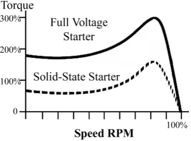
As the motor starts up and picks up speed the starting current falls. The characteristics of the SCIM while starting in the DOL scheme can be clearly comprehended by considering Figure 1 which gives the relevant curves obtained with MATLAB/ SIMULINK.
The objective put forth by the starting scheme discussed in this paper is that throughout the starting phase the starting current is just limited to the optimally required value just enough to take the motor speed to the next higher speed. This operation is repeated in every measurement and control cycle and the whole starting process is smooth with the optimally allowed current that changes step by step with an optimal increment applied for every step throughout the starting period.
A. A. Mohamed Faizal, P. Subburaj
Figure 1. Speed torque characteristics of SCIM.
3. Scheme of Control
Soft starting can be carried out using the auto transformer starter. Auto transformer based soft starting scheme is an analog control system where the wiper of the auto transformer can be rotated in a continuous fashion at a de-sired rate using a servo motor. The digitally controllable servo motor driven auto transformer based soft starting has no apparent draw backs except for the cost, volume and weight and efficiency [7]-[9]. With the advent of modern power electronic devices, it is possible to design at comparatively low cost soft starting schemes that are cheap, less weight and volume with improved efficiency and soft start motor control based on fuzzy theory has been proposed [10] [11].
Analysis of extinction angle control of self-excited induction generator-converter systems for battery charging applications has been presented in [12]. Design and Simulation of Three-phase AC Motor Soft-start scheme have been demonstrated in [13] [14]. Soft start of induction motors using floating capacitor H-bridge converters has been explained in [15]. In [16] the authors proposed a soft-start circuit of the High Voltage Power Supply Based on Pulse Step Modulation Technology.
The control scheme discussed in this paper is a soft starting scheme for the SCIM of 5.4 HP (4 KW)/380V/50 Hz. The idea proposed, tested and validated here is a closed loop style of soft starting. The speed of the motor and the current drawn are continuously monitored. The strategy is that to start with, a certain conduction angle is allowed, and for this applied excitation the resulting rate of rise of current and speed are monitored. Until the rate of rise of current and the rate of rise of speed are monitored and a decision is made based on this informa-tion using the Artificial Neural Network (ANN) based intelligent decision making unit the same excitainforma-tion level or the same conduction angle continues. Once the decision is made the angle of conduction is either incremented or decremented based upon the decision made by the ANN subsystem.
The process of observation of the rate of change of current, speed and the inference made by the ANN and the implementation of the new conduction angle continues repeatedly until the machine reaches the rated speed.
The basic rules followed in the control strategy are as follows.
The rate of rise of current and the rate of rise of speed are calculated based on the measurements of current and speed in real time.
1) If the rate of rise of current is high and the rate of rise of speed is also high then the current conduction an-gle is maintained.
2) If the rate of rise of current is high but the rate of rise of speed is low then the conduction angle is reduced. 3) If the rate of rise of current is low but the rate of rise of speed is high then the conduction angle is in-creased.
4) If the rate of rise of current is low and the rate of rise of speed is also low then the conduction angle is in-creased.
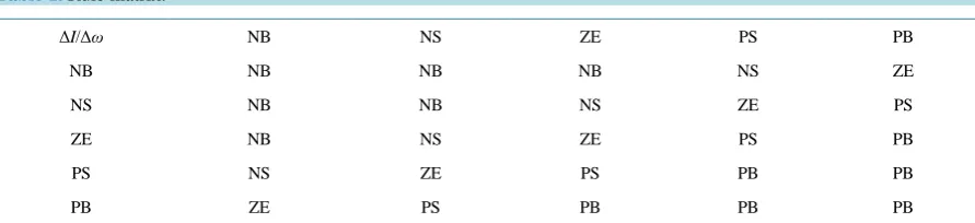
Table 1. Rule matrix.
ΔI/Δω NB NS ZE PS PB
NB NB NB NB NS ZE
NS NB NB NS ZE PS
ZE NB NS ZE PS PB
PS NS ZE PS PB PB
PB ZE PS PB PB PB
suggested by the fuzzy logic controller is recorded over a full starting period.
The same experiment is repeated three times respectively with no load, full load and 50% of full load. Based on the data collected from the three cases an ANN is trained in the MATLAB/SIMULINK environment. After the ANN gets trained the FLC is replaced by the ANN. The performance of the FLC and that of the ANN were studied and recorded. The outcome of this procedure reveals that the ANN is more adaptive than the FLC when it comes for soft starting with different loads on the SCIM.
4. Matlab/Simulink Simulation
A complete SIMULINK model was developed for validating the proposed ANN based soft starting scheme and this section discusses some of the sub systems of simulation. The soft starting scheme model shown in Figure 2
gives the FLC version of the proposed scheme.
The extinction angle control of time axis control is used in this application. The motor is considered to be in the STAR connection. Each of the three lines feeding the motor carry a MOSFET and this main MOSFET, is surrounded by a diode bridge and in this way a single MOSFET for each phase is sufficient as the main power control device for both positive and negative half cycles.
Besides across each of the phase windings is connected to another MOSFET surrounded by another diode bridge and this MOSFET acts as the freewheeling device working for both positive and negative half cycles. Thus in total each phase has two MOSFETs individually surrounded by diode bridges and the whole systems for all the three phases have 6 MOSFETs including the main and the freewheeling MOSFETs.
The control system consists of a comparator to compare a reference against a repeating ramp. The output of the comparator is a positive pulse that starts in each cycle from the zero crossing and extends into the positive half cycle period up to the desired period of conduction. The desired period of conduction is achieved by appro-priately generating the gating pulse which is produced by the comparator that compares the ramp and the refer-ence. The ramp for each phase is respectively synchronized with the corresponding source phase voltage and it runs between 0 and 1 with the same timing as the period of the half cycles of the source phase voltage. The fre-quency of the ramp is just twice the line frefre-quency and the ramp is synchronized for each half cycle of the source voltage. Thus gating pulses for both positive and negative cycles are produced appropriately in a syn-chronized manner.
The conduction period in each half cycle is equal to the width of the pulse and the width of the pulse is a function of the reference and the magnitude of the reference, in the range of 0 to 1, in turn is decided by the FLC/ANN as per the operational requirements of the proposed soft starting system.
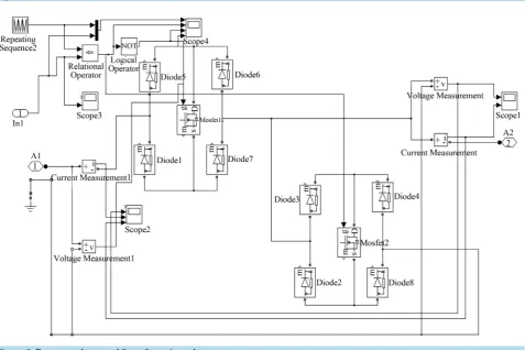
The freewheeling MOSFET is driven by the signal that is just an inverted version of the pulses driving the main power feeding MOSFET. This inversion is carried out using a NOT gate. The power topology is shown in
Figure 3. The rate of rise of current and the rate of rise of speed are derived using the “derivative” block of MATLAB/SIMULINK.
4.1. Fuzzy Logic Controller
A. A. Mohamed Faizal, P. Subburaj
Figure 2. Simulink model of FLC controller.
Figure 3. Power topology used for soft starting scheme.
[image:5.595.61.539.311.629.2]assigned with some name usually a meaningful name pertaining to the range of the contents of the segments. The segments are named typically HIGH, MEDIUM, LOW etc.
The segments on the input side of the FLC are related to the segments on the output of the FLC using the RULE BASE. The rule base is a collection of rules framed by the practically experienced operator by virtue of the past experience gained with the system under control.
In an FLC, decisions are made in two phases. In the first phase the segments of the error and the error rate are related by the rule matrix and the segment of the output to which the next output should belong to which it is identified. After finding the segment to be implemented the degree of membership of the output in the segment is found. After finding the appropriate segment in the UOD of the output and the degree of membership in that segment the result will be defuzzified, denormalised and if necessary descaled to suit the real system.
The MATLAB/SIMULINK screens of the FLC are shown in Figures 4-7. In this particular application the Mamdani type of FLC was used and the UOD of each variable was divided into five segments. Triangular membership functions were adopted for the segments and twenty five rules were formed.
4.2. ANN Controller
As the FLC is in action, during the entire transient period, the inputs to the FLC and the output of the FLC are recorded. The sampling rate used for data collection was 0.00001 sec. The data were collected at the work space of MATLAB. The rate of change of current and speed and the output of the FLC were collected and stored in a file to be used as the training data for the ANN. The ANN we have adopted is of the feed forward back propaga-tion multilayer type with one input layer, one output layer and a hidden layer.
The input vector consists of two elements and the output vector consists of a single element. Therefore the number of neurons in the input layer of the ANN is two and that in the output layer is one. The number of hid-den layer neurons is 7.
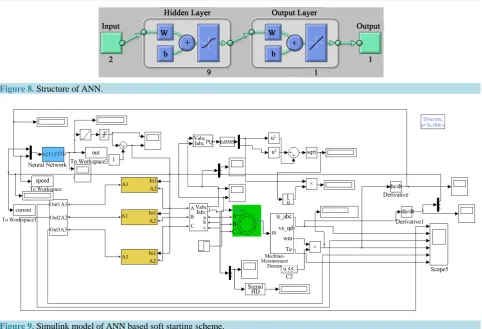
There were thus fourteen synaptic weights on the input side and seven on the output side. The weights of the 21 synapses will be iteratively modified during the training period and will attain the final value when the ANN is sufficiently trained. The structure of the ANN is given in Figure 8.
The MATLAB/SIMULINK subsystems of the ANN based soft starting are given in Figure 9. The results of the ANN based soft starting with all the relevant waveforms are presented in the results and discussions section.
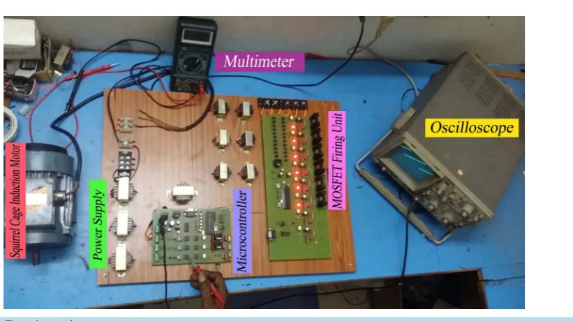
5. Experimental Verification
In order to validate the proposed idea of the ANN based soft starting scheme an experimental verification setup has been constructed. The specifications of the Motor used are given in Table 2.
The power circuit is shown in Figure 10. MOSFET IRF 840 was selected for the main and the freewheeling switches. A diode bridge around the MOSFET devices using diodes 1N 5408. The central control unit was Mi-cro controller PIC 16F877A.
The important subsystems of the scheme are
1) The Power circuit consisting of the opto couplers, MOSFETs and the diode bridges. 2) The motor current monitoring unit.
3) The speed monitoring unit.
4) The synchronized Ramp generation unit. 5) The decision making unit.
6) The DAC and the Comparator.
The block schematic of the soft starting unit is shown in Figure 11.
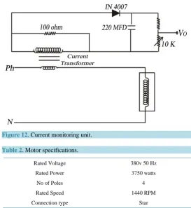
5.1. Current Monitoring Unit
The function of the current monitoring unit is to measure the stator current of the motor. Since the motor is a balanced load a single current measuring unit in the R phase is used. The circuit arrangement of the current monitoring unit is given in Figure 12.
A. A. Mohamed Faizal, P. Subburaj
[image:11.595.57.540.78.407.2]Figure 8. Structure of ANN.
[image:11.595.86.542.330.695.2]Figure 9. Simulink model of ANN based soft starting scheme.
Figure 10. Power circuit topology.
Figure 12. Current monitoring unit.
Table 2. Motor specifications.
Rated Voltage 380v 50 Hz
Rated Power 3750 watts
No of Poles 4
Rated Speed 1440 RPM
Connection type Star
The voltage across the burden resistor is rectified and filtered and the ultimate voltage across the capacitor with a bleeder resistor gives a measure of the stator current drawn by the motor. An attenuator is provided to calibrate this voltage to be in the range of 0 to 5 volts and appropriately represent the motor stator current.
This analog voltage is fed to the PIC 16F877 wherein there is a built in ADC that converts the analog signal into the corresponding digital data.
5.2. Speed Monitoring Unit
The speed monitor unit is based on the frequency (F) to voltage (V) conversion. A slot sensor in association with a disc with uniformly spaced perforations on the periphery of the disc is fixed to the shaft of the motor. This ar-rangement is used to continuously generate a train of pulses. The frequency of the pulses generated by the slot sensor is a function of the speed of the motor.
With 24 perforations on the disc the frequency generated for a speed of, say, 1200 RPM can be calculated as follows.
Pulses per revolution = 24
Revolutions/second = 1200/60 = 20 Pulses per second = 24 × 20
Frequency of the pulse train = 480 Pulses/second.
Similarly the Frequency of the pulse train for a maximum speed of 1500 RPM will be (1500/60) × 24 = 600 Pulses/second.
The circuit arrangement for the frequency to voltage convertor is as shown in Figure 13.
For the given circuit arrangement with the component values shown the output voltage of the F to V converter will vary between 0 and 5 volts. This analog voltage is fed to the PIC 16F877A wherein there is a built in ADC that converts the analog signal into the corresponding digital data. The complete experimental verification setup is shown in Figure 14.
5.3. Estimation of Rate of Change of Current and Speed
A. A. Mohamed Faizal, P. Subburaj
Figure 13. Circuit arrangement for frequency to voltage converter.
Figure 14. Experimental setup.
and the speed of the motor. This monitoring process is repeated after a short delay and the change in the values of the parameters monitored in the consecutive measurement cycles gives the rate of change of the parameters.
After getting the rate of change of current and speed this data is logged into the fuzzy engine segment of the program for making the decision as to how much the conduction angle should be altered.
5.4. Implementation of ANN in the Micro Controller
[image:13.595.124.535.371.601.2]MATLAB Neural Network tool box a SIMULINK block representing the ANN is created. If this SIMULINK block is opened we can check the values of the synaptic weights and these values are noted down.
The synaptic weights noted down from the ANN block of SIMULINK is stored in a set of variables in the micro controller programming developed in C language. The Tan Sigmoidal function used as the activation functions of the Neurons can be easily implemented in the micro controller programming environment. Thus the synaptic weights and the activations are brought into the microcontroller environment and this segment of the microcontroller program will behave in the same manner as the ANN developed and used in MATLAB. The typical program segment used in the implementation of the Tan Sigmoidal Function of the ANN in the PIC mi-cro controller environment is shown below.
float tansig(float input) { float r;
r = (1/(1+exp(-input))); return r;
}
6. Results and Discussion
The results of the MATLAB/SIMULINK simulations are first illustrated followed by the results of the experi-mental verification.
A. A. Mohamed Faizal, P. Subburaj
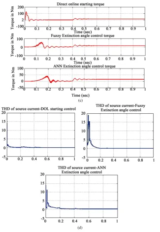
Figure 15. Comparison of (a) Stator current, (b) Speed in RPM, (c) Torque in NM and (d)
THD.
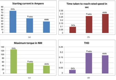
that the DOL starting scheme offers the shortest starting period. But the current drawn during the starting period is comparatively as high as 80 A. The Conventional fuzzy logic control scheme offers a smooth starting but still the starting current in all the three phases reach as high as and little more than 50 A. The ANN based soft start-ing scheme offers the best startstart-ing behavior and it offers the lowest maximum startstart-ing current of 30 A as com-pared to the other methods.
A consideration of Figure 15(b) reveals that with the ANN based soft starting scheme the motor takes a longer time of 0.2 second whereas FLC offers 0.12 second to reach the steady state speed. The starting current also falls down from the higher values during transient period to the lower steady state level in the same timing as the speed moves on to the steady state speed from rest.
Nm respectively. A momentary very high starting torque as exhibited by the DOL scheme of starting leads to slowly develop mechanical instabilities and in due course the mechanical systems may get damaged, compara-tively earlier than with the case of the other two starting schemes. Therefore Figure15(c) clearly shows that the proposed technique of soft starting with fuzzy logic trained ANN offers relatively the best torque profile.
With the ANN based soft starting scheme outperforming the other schemes of starting in regard to the para-meters discussed earlier the last concern is the quality of power drawn from the mains. The soft starting schemes usually, while offering a smooth soft starting scheme for the machine under consideration it may lead to the pollution of the feeding electrical system.
With reference to Figure 15(d) it is clear that the DOL starting scheme is the best in terms of the recorded minima of the maximum Total Harmonic Distortion (THD) and this is possible because the DOL scheme does not use any phase control or extinction angle control technique. But with the other two schemes of soft starting the ANN based scheme offers better harmonic performance by offering reduced THD compared to the fuzzy logic based soft starting scheme. Figure 16 consolidates in a bar graph the comparison of starting current, start-ing period, Maximum Torque and THD durstart-ing the startstart-ing period in all the three cases.
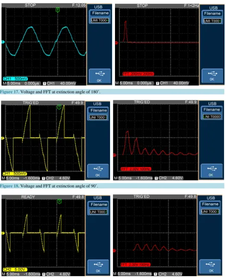
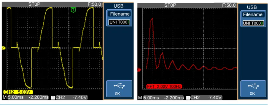
Figures 17-20 give a picture of the voltages passed on to the load through the extinction angle controller. A comparison of the load side voltage waveform for different conduction angles or durations of conduction in each cycle with conduction periods nearly 180 degrees, 90 degrees, less than 90 degrees and the case with little more than 90 degrees of conduction along with their respective FFT plots are shown.
It is clear that at lower conduction angles near the starting instant the THD is as high as the conduction angle approaches 90 degrees the THD is moderate and when the conduction period is as high as 180 degrees the waveform of voltage is nearly sinusoidal and the FFT shows only the fundamental quantity.
[image:16.595.92.538.391.699.2]Therefore it can be inferred strongly, by considering all the relevant performance parameters, that the ANN based closed loop soft starting scheme is the best possible soft starting scheme that can be implemented with the three phase squirrel cage induction motor.
Figure 16. Graphical comparison of (a) Starting current, (b) Time taken to reach rated speed, (c) Maximum torque and (d)
A. A. Mohamed Faizal, P. Subburaj
Figure 17. Voltage and FFT at extinction angle of 180˚.
Figure 18. Voltage and FFT at extinction angle of 90˚.
Figure 19. Voltage and FFT at extinction angle less than 90˚.
7. Conclusion
Figure 20. Voltage and FFT at extinction angle greater than 90˚.
THD have been taken into analysis. Simulation was carried out with both FLC and ANN and compared. The ANN technique proves to be better than FLC, in terms of the above said parameters taken into consideration. This research work can be further extended with the use of Adaptive Neuro Fuzzy Inference System (ANFIS) technology and could be fine tuned using Genetic Algorithm. The outcome of the experimental results shows that ANN based soft starting outperforms the FLC based soft starting.
References
[1] Zenginobuz, G., Cadirci, I., Ermis,M. and Barlak, C. (2001) Soft Starting of Large Induction Motors at Constant Cur-rent with Minimized Starting Torque Pulsations. IEEE Transactions on Industry Applications, 37, 1334-1347.
[2] Wang, Y., Zhao, K.Q. and Xu, D.G. (2002) Research on Displacement Angle in the Control System of Motor Soft Starter. Proceedings of the Chinese Society for Electrical Engineering, 22, 82-86.
[3] Lu, G.Q., Ji, Y.C., Yu, H.X. and Zhang, K. (2003) Analysis of a Novel Topology of Soft Starter for Induction Motors.
Industrial Electronics Society, IECON’03, 1, 2-6.
[4] Gastli, A. and Ahmed, M.M. (2005) ANN-Based Soft Starting of Voltage-Controlled-Fed IM Drive System. IEEE Transactions on Energy Conversion, 20, 497-503.
[5] Kashif, A.R. and Saqib, M.A. (2007) Soft Starting of an Induction Motor Using Adaptive Neuro Fuzzy Inference Sys-tem. Proceedings of International Conference on Electrical Engineering, Lahore, 11-12 April 2007, 1-5.
http://dx.doi.org/10.1109/icee.2007.4287353
[6] Eltamaly, A.M., Alolah, A.I. and Hamouda, R.M. (2007) Performance Evaluation of Three-Phase Induction Motor un-der Different AC Voltage Control Strategies Part I. International Aegean Conference on Electrical Machines and Power Electronics, Bodrum, 10-12 September 2007, 770-774.
[7] Charles, S. and Bhuvameswari, G. (2009) Power Quality Studies on a Soft Start for an Induction Motor. International Journal of Recent Trends in Engineering, 1, 261-265.
[8] Sun, Z.P. (2009) Summary of the Electro Motor Soft-Start Technology. Journal of Jilin Institute of Chemical Tech-nology, 3, 70-75.
[9] Siddiqui, U.F., Verma, A. and Soni, S. (2013) Analysis of Induction Motor by Soft Starters Using Power Switching Devices. International Journal of Advanced Electronics & Communication Systems, 2, Article ID: 70-141-2-SM. [10] Li, T. and Jiang, L.J. (2010) Adaptive Neuro Fuzzy Based Soft Starting of DC Motor. International Conference on
Electrical and Control Engineering (ICECE), Wuhan, 25-27 June 2010, 3261-3264.
http://dx.doi.org/10.1109/icece.2010.796
[11] Feng, Z. and Liu, S. (2010) Electric Motor Soft-Start Control Based on Fuzzy Theory. 3rd International Conference on Intelligent Networks and Intelligent Systems, Shenyang, 1-3 November 2010, 430-433.
http://dx.doi.org/10.1109/icinis.2010.125
[12] Karthigaivel, R., Kumaresan, N. and Subbiah, M. (2011) Analysis and Control of Self-Excited Induction Generator- Converter Systems for Battery Charging Applications. IET Electric Power Applications, 5, 247-257.
A. A. Mohamed Faizal, P. Subburaj
[13] Li, S. (2013) Design and Simulation of Three-Phase AC Motor Soft-Start. International Conference on Intelligent Sys-tem Design and Engineering Applications (ISDEA), Hong Kong, 16-18 January 2013, 554-557.
http://dx.doi.org/10.1109/isdea.2012.135
[14] Bumroongphuck, C. (2013) Soft Starting Method for Single-Phase PWM AC Chopper Fed Three-Phase Induction Motor. International Conference on Electrical Machines and Systems (ICEMS), Busan, 26-29 October 2013, 1991- 1995. http://dx.doi.org/10.1109/ICEMS.2013.6713183
[15] Leng, S., Ul Haque, R., Perera, N., Salmon, J. and Knight, A. (2014) Soft Start of Induction Motors Using Floating Capacitor H-Bridge Converters. IET International Conference on Power Electronics, Machines and Drives, 1-6.
http://dx.doi.org/10.1049/cp.2014.0341
[16] Xia, L.L., Zhang, M., Ma, S., Zhuang, G. and Yu, K. (2014) Analysis of the Soft-Start Circuit of the High Voltage Power Supply Based on PSM Technology. IEEE Transactions on Plasma Science, 42, 1026-1031.
Submit or recommend next manuscript to SCIRP and we will provide best service for you:
Accepting pre-submission inquiries through Email, Facebook, LinkedIn, Twitter, etc. A wide selection of journals (inclusive of 9 subjects, more than 200 journals) Providing 24-hour high-quality service
User-friendly online submission system Fair and swift peer-review system
Efficient typesetting and proofreading procedure
Display of the result of downloads and visits, as well as the number of cited articles Maximum dissemination of your research work