UNIVERSITI TEKNIKAL MALAYSIA MELAKA
TO STUDY THE CONCEPT OF PERPETUAL MOTION ON
CEILING FAN BY USING PERMANENT MAGNET
This report is submitted in accordance with the requirement of the Universiti Teknikal Malaysia Melaka (UTeM) for the Bachelor of Mechanical Engineering
Technology (Automotive Technology) with Honours
by
ADI AZRI BIN NGAHDIMAN B071410743
921223-01-6429
UNIVERSITI TEKNIKAL MALAYSIA MELAKA
BORANG PENGESAHAN STATUS LAPORAN PROJEK SARJANA MUDA
TAJUK: TO STUDY THE CONCEPT OF PERPETUAL MOTION ON CEILING FAN BY USING PERMANENT MAGNET
SESI PENGAJIAN: 2017/18 Semester 1
Saya ADI AZRI BIN NGAHDIMANmengaku membenarkan Laporan PSM ini disimpan di Perpustakaan Universiti Teknikal Malaysia Melaka (UTeM) dengan syarat-syarat kegunaan seperti berikut:
Laporan PSM adalah hak milik Universiti Teknikal Malaysia Melaka dan penulis.Perpustakaan Universiti Teknikal Malaysia Melaka dibenarkan membuat salinan untuk tujuan pengajian sahaja dengan izin penulis.
Perpustakaan dibenarkan membuat salinan laporan PSM ini sebagai bahan pertukaran antara institusi pengajian tinggi.
**Silatandakan ( )
SULIT
TERHAD
TIDAK TERHAD
( Mengandungi maklumat yang berdarjah keselamatan atau kepentingan Malaysia sebagaimana yang termaktub dalam AKTA RAHSIA RASMI 1972 )
( Mengandungi maklumat TERHAD yang telah ditentukan oleh organisasi / badan di mana penyelidikan dijalankan )
Di sahkan oleh:
Cop Rasmi:
**Jika Laporan PSM ini SULIT atau TERHAD, sila lampirkan surat daripada pihakberkuasa / organisasi berkenaan dengan menyatakan sekali sebab dan tempoh laporan PSM ini perlu dikelaskan sebagai SULIT atau TERHAD.
Alamat Tetap:
Lrg. Haji Hashim, Kg. parit Tegong, Rimba Terjun, 82000 Pontian ,
Johor Darul Takzim
Tarikh:
DECLARATION
I hereby, declared this report entitled “To Study the Concept of Perpetual Motion on Ceiling Fan by Using Permanent Magnet” is the results of my own research except as cited in references.
Signature :
Author’s Name : ADI AZRI BIN NGAHDIMAN
APPROVAL
This report is submitted to the Faculty of Engineering Technology of UTeM as a partial fulfillment of the requirements for the degree of Bachelor of Mechanical Engineering Technology (Automotive) with Honours. The member of the supervisory is as follow:
EN MUHAMMED NOOR BIN HASHIM ………
i ABSTRAK
ii ABSTRACT
iii DEDICATION
Special dedication to my beloved family members, especially to my father, Ngahdiman bin Hashim, my mother Zuridah binti Bachok, my sibling Adi Azizi, Ida Nadia, Ida Naziera, Ida Nadiera and Ida Nazura who always supported and encouraged me with motivation and love through my whole journey.
To my respected and professional supervisor, Sir Muhammed Noor Bin Hashim who introduced me to this project and he gave me an inspiration idea about the project and endless guidance and persistent help to complete this project thesis.
iv ACKNOWLEDGEMENT
All praise belongs to ALLAH (SWT). Without the health, strength and perseverance He gave, I would not be able to complete this project thesis. I have taken efforts in this project and spend time wisely to complete this thesis. However, it would have not been possible without the kind support and help of many individuals.
In particular, I want to thank to anyone that contributed in my project thesis. They have encouraged me and giving full thought during this project. First, I would like to express the deepest appreciations to my supervisor Sir Muhammed Noor Bin Hashim for his patient and endless supports that continually teaching me throughout my project. He gave me a necessary suggestions and constant supervision as well as for providing information regarding the project thesis. Without his guidance and persistent help this project thesis would not complete successfully.
I also want to express my gratitude towards my beloved parents and families for their kind motivation to go through all the hard works and they gave me their supports and positive vibes while carrying out this project.
v LIST OF CONTENTS
CHAPTER 1: INTRODUCTION 1
1.0 Introduction 1
1.1 Research background 2
1.2 Problem statement 11
1.3 Objective 12
1.4 Scope 12
CHAPTER 2: LITERATURE REVIEW 13
2.0 Introduction 13
2.1 Magnet 13
2.2 Perpetual motion 17
2.3 Ceiling Fan 21
CHAPTER 3: RESEARCH METHODOLOGY 29
3.0 Introduction 29
3.1Project briefing 31
3.2 Conceptual Design 31
3.5 Method Selection 33
3.6 Measurement Analysis 33
CHAPTER 4: RESULT AND DISCUSSION 36
vi
4.1 Project briefing 36
4.2 Market Survey 37
4.3 Multivoting Result 39
4.4 Concept Design Drawing 39
4.5 Fabrication 41
4.6 Result 46
CHAPTER 5: CONCLUSION AND RECOMMENDATION 48 5.1 Introduction 48
5.2 Conclusion 48
5.3 Recommendations 49
vii LIST OF FIGURES
Figure 1-1: A fan that made from palm frond. 2
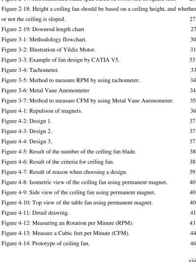
Figure 1-2: A 'Punkah' fan. 2
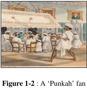
Figure 1-3: Belt driven ceiling fan. 3
Figure 1-4: Phillip Diehl. 3
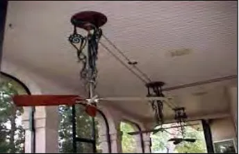
Figure 1-5: The first electric ceiling fan of Phillip Diehl. 4
Figure 1-6: 1920 Ceiling fan. 4
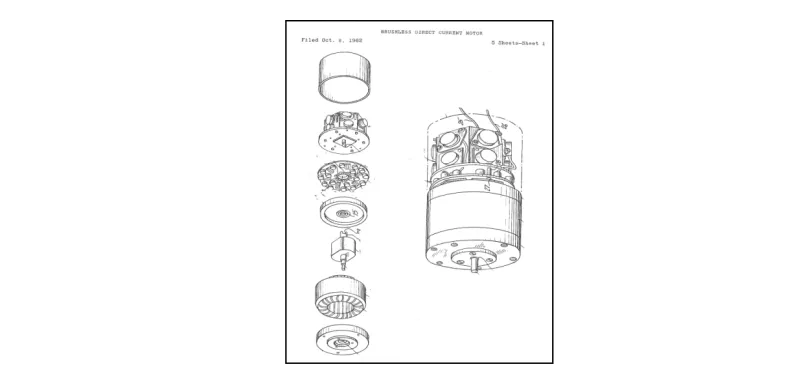
Figure 1-7: 1962 Brushless direct current motors. 5
Figure 1-8: Bhaskara Wheel. 6
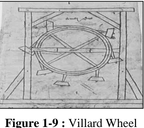
Figure 1-9: Villard Wheel. 6
Figure 1-10: Model of Taccola's wheel at Deutches museum. 7
Figure 1-11: Leonardo's drawing of perpetual motion. 7
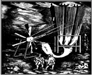
Figure 1-12: Illustration of Zimara's windmill by Burton Lee Potterfield. 7
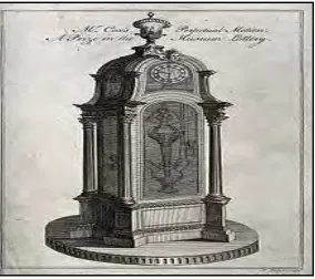
Figure 1-13: Perpetual Goblet. 8
Figure 1-14: Cox's timepiece. 8
Figure 1-15: Lodestone. 9
Figure 1-16: Assortment of Alnico alloy permanent magnets. 10
Figure 1-17: Neodymium-Iron Boron Magnet. 11
Figure 2-1: Opposite polarity two magnetic poles. 13
Figure 2-2: Similar polarity two magnetic poles. 14
Figure 2-3: Conventional magnetizing fixture. 17
Figure 2-4: Basic elements of capacitor discharge magnetizer. 19
Figure 2-5: Wilkins Perpetual motion machines. 19
Figure 2-6: Magnet driven wheel. 19
Figure 2-7: Automatic Armilarry Sphere 20
Figure 2-8: Blade pitch. 23
Figure 2-9: Hugger type ceiling fan. 23
Figure 2-10: Brushless direct current motor (BLDC) for ceiling fan. 23
Figure 2-11: Ceiling fans with varying number of blades. 24
viii
Figure 2-13: Mass Flow Rate. 24
Figure 2-14: Torque. 24
Figure 2-15: For odd number blades of fan, measure the distance from the center of fan to blade tipthe multiply that number by 2. 26
Figure 2 -6: If even number of blades, measure the distance between opposing blades. 26
Figure 2-17: Recommended blade span based on room size in square feet. 26
Figure 2-18: Height a ceiling fan should be based on a ceiling height, and whether or not the ceiling is sloped. 27
Figure 2-19: Downrod length chart 27
Figure 3-1: Methodology flowchart. 30
Figure 3-2: Illustration of Yildiz Motor. 31
Figure 3-3: Example of fan design by CATIA V5. 33
Figure 3-4: Tachometer. 33
Figure 3-5: Method to measure RPM by using tachometer. 34
Figure 3-6: Metal Vane Anemometer 34
Figure 3-7: Method to measure CFM by using Metal Vane Anemometer. 35
Figure 4-1: Repulsion of magnets. 36
Figure 4-2: Design 1. 37
Figure 4-3: Design 2. 37
Figure 4-4: Design 3. 37
Figure 4-5: Result of the number of the ceiling fan blade. 38
Figure 4-6: Result of the criteria for ceiling fan. 38
Figure 4-7: Result of reason when choosing a design. 39
Figure 4-8: Isometric view of the ceiling fan using permanent magnet. 40
Figure 4-9: Side view of the ceiling fan using permanent magnet. 40
[image:12.612.141.539.206.738.2]Figure 4-10: Top view of the table fan using permanent magnet. 40
Figure 4-11: Detail drawing. 41
Figure 4-12: Measuring an Rotation per Minute (RPM). 43
Figure 4-13: Measure a Cubic feet per Minute (CFM). 44
ix LIST OF TABLE
Table 2-2: Summary of permanent magnet application. 16
Table 2-3: Magnetic property requirements for different application. 16
Table 2-4: Ceiling fan size guide. 27
Table 4-1: Material selection. 42
x LIST OF ABBREVIATIONS, SYMBOLS AND NOMENCLATURE
2D - Two-Dimensional 3D - Three-Dimensional AC - Alternating Current
Br - Remnant Flux Density / Remanance BH max - Energy Product
DC - Direct Current
CAD - Computer Aided Design
CATIA - Computer Aided Three-Dimensional Interactive Application CFM - Cubic Feet Per Minute
Hci - Coercivity
1 CHAPTER 1
INTRODUCTION
1.0 Introduction
These projects are focused on study a perpetual motion ceiling fan by using permanent magnets. The concept will be based on perpetual motion that is body motion that carries on indefinitely. In this project, we must understand the overview concept of perpetual motion to design the mechanism and the prototype.
The movement of a theoretical machine that once actuated, would run until the end of time unless subject to an external force or to wear. Magnets that have the same polarity will produce a repulsive force that utilized to move or rotate the blade ceiling fan.
2 1.1 Research background
1.1.1 Ceiling fan
[image:16.612.250.403.258.415.2]The advancement of ceiling fan was an essential huge occasion in the realm of electrical machines. This apparatus is one that has been disregarded by practically everybody with regards to advancement. In any case, regardless they are a straightforward and reasonable wellspring of break from hot atmospheres in tropical nations.
Figure 1-1: A fan that made from palm frond.
In the mid 17th century in India, a comparable sort of fan was the 'punkah', a palm frond swung from the ceiling that moved when a servant pulled a rope.
Figure 1-2 : A ‘Punkah’ fan
[image:16.612.256.398.506.651.2]3 most usually in the southern and south western states like Texas, Louisiana , Mexico, and Arizona, and this was indeed before the common utilize of power.
Figure 1-3 :Belt driven ceiling fan
[image:17.612.267.439.123.234.2]In 1882, German-American man named Philip Diehl made electrically powered ceiling. An electric motor that he had intended for use in the Singer sewing machines was introducing it into what might be the world's first ceiling fan.
Figure 1-4 : Phillip Diehl
4 Figure 1-5: The first electric ceiling fan of Phillip Diehl
Ceiling fans were becoming common in the United States in 1920. The ceiling fan operated with four blades instead of the original two blades, which allowed them to be quieter and made fans circulate more air.
Figure 1-6 : 1920 Ceiling fan
Ceiling fans gradually began to phase out from prevalent usage in the United States when the air conditioners were presented in the 1950s. But as that was happening, they started getting to be gigantically prevalent in different tropical nations like India and other African nations.
During the energy crisis late 1970 and early 1980, Crompton-Greaves Ltd. And Encon Industries have made a few changes in acknowledgment motor development and led to the production of ceiling fans which consume a power around 70 Watt to 80 Watt. Numerous American producers have also begun altogether expanding the number of ceiling fans produced due to this re-established commercial victory utilizing ceiling fans successfully to save energy. But the world of ceiling fans did not see much advancement after this period ended with broad utilization in a few countries.
5 engines or BLDC engines to begin with made in 1962. But it was utilized in ceiling fans by Emerson Electric in the United States in 2009, after nearly 47 years afterward. This new motor innovation introduced in a modern era of energy efficient ceiling fans reduced power utilization indeed encouraging underneath 50W.
Figure 1-7 : 1962 Brushless direct current motors
This innovation was first brought in India by Versa Drives Pvt. Ltd when they launched Super fan and accomplish a power utilization of 35W. Furthermore, Atom berg Technologies, with the Gorilla Fans have taken power, sparing to another level out and out by launching 28W fan. This while accomplishing the same level of execution from any ordinary 70W to 80W fan. Where 22% of the people in India still do not approach electric power, innovation and advancements are required that can empower us to save vitality or take advantage of substitute vital sources.
1.1.2 Perpetual motion machine.
6 Figure 1-8 : Bhaskara Wheel
The 13th century French ace artisan and planner, Villard de Honnecourt has a drawing of a never-ending movement machine in his sketchbook. With his ceaseless machine, Villard's Wheel, Villard de Honnecourt said that many a time have skilful laborers attempting to think up a wheel that should turn of itself. Here is a way to make such a one, by implying of an uneven number of hammers, or by mercury (mercury).
Figure 1-9 : Villard Wheel
[image:20.612.257.400.345.472.2]7 Figure 1-10 : Model of Taccola's wheel at Deutches museum.
Leonardo da Vinci was made a number of drawings of devices. He trusted that he would make free energy. In spite of the fact that he was by and large against such
[image:21.612.163.491.306.415.2]devices, but he interested drew and inspected various over adjusted wheels.
Figure 1-11 : Leonardo’s drawing of perpetual motion
The 16thcentury Italian scholar, Mark Anthony Zimara was proposed a self-blowing windmill.
[image:21.612.253.402.518.641.2]8 Cornelius Drebbel in "Wonder-vondt van de euwighebewegingh" devoted a Ceaseless movement machine to James I of Britain in 1607. In 1621, it was depicted by Heinrich Hiesserle von Chodaw. Robert Boyle fabricates the "never-ending vase" which was talked about by Denis Papin in the Philosophical Exchanges for 1685. Johann Bernoulli proposed a fluid energy machine.
Figure 1-13 : Perpetual Goblet.
A self-powered water process and a few never-ending development machines using balls utilizing varieties of Archimedes screws were arranged by George Andreas Bockler in 1686. In 1712, Johann Bessler (Orffyreus) was examining 300 unmistakable perpetual movement models and he claimed that all the illustrate have the secret of never-ending motion
James Cox and John Joseph Merlin created Cox's timepiece in 1760. Cox claimed that the timepiece was a genuine perpetual motion machine, but as the device was powered by changes in barometrical weight through a mercury barometer.
Figure 1-14 : Cox's timepiece.
[image:22.612.258.400.496.622.2]9 1.1.3 Magnet
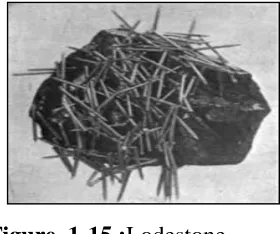
[image:23.612.274.414.236.353.2]Magnes, the legend of Shepherd who lived in Magnesia near Mount Ida in Greece is the most well known history for the revelation of magnets. Mount Ida was alluded to as the "Mountain of the Goddess". Roughly 2,600 a long time prior (600 BC) Magnes found that the nails and buckle of his shoes and the tip of his staff were attracted to the rock he was standing on while shepherd sheep on the mountain. He burrowed up the soil to discover lodestones. Lodestones contain magnetite, a characteristic attractive fabric Fe3O.
Figure 1-15 :Lodestone
The word magnet is determined from the Greek title, lithos magnetism. The stone of Magnesia alluding to the locale on the Aegean coast in present-day Turkey where these attractive stones were found.
The English man named Alexander Neckam records the earliest European understanding of the early magnet compass as a guide to seamen in approximately 1180. The term of lodestone comes from the Anglo-Saxon that mean "driving stone" or actually "the stone that leads”. Eider-stein, the Icelandic word and was used in writings of that period in reference to the route of ships.
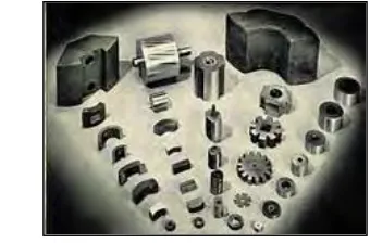
10 In the early 1900s, researchers began examining magnetic materials other than those based on iron and steel. By the 1930, Alnico alloy is the first effective permanent magnets had created by researchers
Figure 1-16 : Assortment of Alnico alloy permanent magnets.
In 1966, the first uncommon soil magnets were created from Samarium-Cobalt (SmCo5) creating a high energy item of 18 MGOe. In 1972, an advance improvements were made utilizing Samarium-Cobalt (Sm2Co17) to create a higher energy magnet item of 30 MGOe.
The high energy item of 35 MGOe from a compound of Neodymium-Iron-Boron (Nd2Fe14B) alluded to as neo magnets or uncommon soil magnets was created by General Motors, Sumitomo Special Metals and the Chinese Foundation of Sciences in 1983. Neo magnets are the most grounded sort of permanent magnet in the world. The colossal intrigued these magnets have created emerges since for the to begin with time, a modern magnetic material has been presented which is not as it was more grounded than the past era but is more efficient.