1
PERFORMANCE OF COOPERATIVE COMMUNICATION
SYSTEM WITH NETWORK CODING USING
SOFTWARE DEFINED RADIO
1SUWADI, 2ENDROYONO, 3TITIEK SURYANI, 4UMMUL KHAIR
1,2,3,4Department of Electrical Engineering, Institut Teknologi Sepuluh Nopember (ITS)
SURABAYA, INDONESIA, 60111
E-mail: {1suwadi, 2endroyono, 3titiks}@ee.its.ac.id, 4[email protected]
ABSTRACT
Network coding is a technique where the transmitted data is encoded and decoded to increase throughput, reduce delays and building a stronger network. Physical network coding (PNC) was originally proposed as a way to boost the performance of Network coding using electromagnetic waves. Cooperative communication aims to reduce fading multipath interference. Amplify and forward (AF) cooperative communications system is the information sent to the relay node will be strengthened and sent to the node destination. This article presents AF cooperative communication systems without and with network coding were implemented on Software Defined Radio module (SDR) was Wireless Open-Access Research Platform (WARP). Furthermore, the measurement of system performance is throughput of the system in indoor and outdoor environment at LOS and NLOS condition. Based on the results of measurement throughput of the system in the indoor environment indicated that cooperative communication system with network coding yield increase of 14% throughput without network at LOS condition and 20% at NLOS condition. While in the outdoor environment indicated increase of 16% throughput at LOS and NLOS condition.
Keywords: AFCooperative Communication Systems, Amplify and Forward, Physical Network coding, throughput,
SDR, WARP.
1.
INTRODUCTIONWireless communication has been progressing over the last two decades. Each new generation of
wireless devices has brought important
improvements in terms of reliability, data rates, device sizes, battery life, and network connectivity [1]. Wireless communication performance is not necessarily protected from disturbances such as fading. Cooperative communications system serves to eliminate the influence of fading on a wireless channel, so that it can improve the performance of the system [2-3]. To improve the performance of cooperative communication systems, network coding offers a new paradigm for communications networks. By using network coding, then the speed problems of download of files, storage, messaging, interactive communication, efficiency in the distribution of content and the problem of packet loss can be completed, so that internet users find it easier to access downloaded files in large quantities, in other words network coding will increase system performance on the internet [4]. PNC is one of three concepts of network coding which was originally proposed as a way to increase
2 without network coding. Throughput analysis was focused in these paper.
This paper is outlined as follows. Section 2 gives basic theory abaut the description of cooperative communication system, network coding and software defined radio. In Section 3 gives the description of system model. Performance analysis and measurement results are presented Section 4. It is followed by the conclusions of this paper in Section 5.
2.
BASIC THEORY2.1 Wireless Communication Systems
In the wireless communication system, there are two types of signal transmission in the wave propagation are Line of Sight (LOS) and Non Line of Sight (NLOS) [2]. Line of Sight (LOS) is the propagation of radio waves from the transmitting antenna to the receiving antenna without any obstruction (obstacle) due to the signal propagation process occurs directly (direct path) and one pass (single path). While the Non Line of Sight (NLOS) propagation of radio waves is propagating from the transmitter antenna to a receiver antenna through a lot of paths (multipath). This is because the radio signals passing through free space (atmospheric) or other obstructions such as trees, buildings, mountains and so experience the reflection, refraction and scattering during the process of propagation that can cause fading.
Fading is a disorder that causes a decrease in the signal power of the received signal so that the signal condition can not be recognized anymore (error). In this case, rayleigh fading channel is modeled when the received signal is no element of direct signal from the transmitter to the receiver or in other words the transmitted signal is Non Line of Sight (NLOS). In addition, the other types of fading is Rician fading that can be modeled if the received signal is a signal directly from the transmitter or in other words the transmitted signal is Line of Sight (LOS )[1].
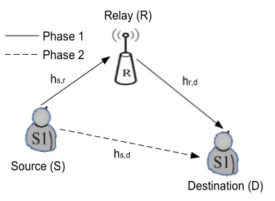
2.2 Cooperative communication system
Cooperative communication system is a mechanism that pools resources from distributed nodes to improve the overall performance of the wireless network. In cooperative communication systems, source (S) sends the information broadcast to the receiver (D) and to relay (R) which is the other users in the area are located nearby. Then the signal received by R will be processed first and then sent to D. The signals received from the sender
Source (S)
Destination (D) Relay (R)
Phase 1 Phase 2
hs,r
hs,d
[image:2.612.322.515.89.230.2]hr,d
Figure 1: Cooperative communication systems
or from the relay will experience the process of combining in the receiver [3]. Cooperative communication system aims to reduce the amount of fading. Simple description of the cooperative communication model is shown in Figure 1.
hs,r : channel loss from source-relay
hs,d : channel loss from source-destination
hr,d : channel loss from relay-destination
Source transmits information to a destination and
relay in the same time. The signals received at ys,d ,
ys,r can be written as follows:
𝑦, = √𝑃 ℎ, 𝑥 + 𝑛, (1)
𝑦, = √𝑃 ℎ, 𝑥 + 𝑛, (2)
Relay will pass the information from source to
destination. The signals received at yr,d is written as
follows:
𝑦 , = ℎ , 𝑞(𝑦, ) + 𝑛 , (3)
where :
𝑦, : received signals at the source-relay
𝑦, : received signals at the source-destination
𝑦 , : received signals at the relay-destination
P : transmit power of source
𝑥 : information symbols
𝑛, , 𝑛, , 𝑛 , : additive noise
q : table function q(.)
2.3 Scenario of cooperative communication
3 Source (S)
Destination (D) Relay (R)
hs,r
hs,d
hr,d
Destination (D) Relay (R)
hs,r
hs,d
hr,d
[image:3.612.138.441.69.226.2](a) (b)
Figure 2: Cooperative communication scenario (a) relay scenario ; (b) symmetry scenario
2.4 Amplify and forward relay protocol [3]
In relay protocol of amplify and forward, the signals received by the relay contained amplified noise prior to normalize the signal caused by fading. Then it is sent back to the destination without decoding process. Illustration of amplify and forward [3] is shown in Figure 3.
This method is called the fixed method which protocol is used when the relay processing time owned a little while power provided much so that the decoder and encoder should be reduced and replaced with reinforcement using the equation:
𝛽 ≤
,
(4) where :
P : transmit power
𝑎 , : fading coefisien between source and relay 𝑁 : noise varians
Source (S)
Destination (D) Relay (R)
Phase 1 Phase 2
1 1
0 0 10 0
1 0
[image:3.612.316.505.301.586.2]0 0 1 0 0
Figure 3: Amplify-and-forward relay
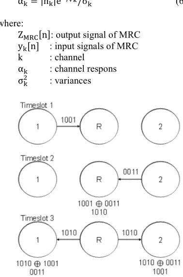
2.5 Maximum ratio combining (MRC) [10]
This technique is combining the sum all signal information received then the sum is detected to obtain the estimates of the transmitted data. At MRC techniques each received signal will be multiplied by the conjugate of the channel coefficient that has passed. Results of maximum ratio combining written to the following equation:
[image:3.612.93.290.415.611.2]Z [n] = ∑ α y [n] (5)
α = |h |e /σ (6)
where:
Z [n]: output signal of MRC
y [n] : input signals of MRC
k : channel
α : channel respons
σ : variances
Figure 4: Network coding Schema
2.6 Network coding[11]
4 so that network users more easily in the access to download large files [4]. Network coding can increase throughput, robustness, complexity, and security. Network coding potential advantage is the efficiency of the resources (bandwidth and power) and computational efficiency. Network coding is a technique where the transmitted data is encoded and decoded to increase throughput, reduce delays and building a stronger network. Here's how the delivery of information on network coding can be showed in figure 4.
2.7 Physical Layer Network coding (PNC)
Schema [5]
At the physical layer network coding is expected to reduce the number of time slots, requires only two timeslots to transmit packets simultaneously and modify operations Network coding is naturally the EM wave. This allows the first node and the second node to transmit the information together so that it can increase the throughput of up to 100%. Figure 5 illustrates the schematic of physical layer network coding. In the first slot, node 1 and node 2 transmits information at S_1dan S_2 simultaneously to the relay. Based on EM wave superposition bring S_1dan S_2, relay
R encodes S_R = S_1⨁S_2. Then in the second
timeslot, the relay R broadcast S_R to node 1 and node 2.
1
S1
SR
S2
SR
R 2
[image:4.612.94.297.438.486.2]Timeslot 1 Timeslot 3
Figure 5 Physical Layer Network coding Schema
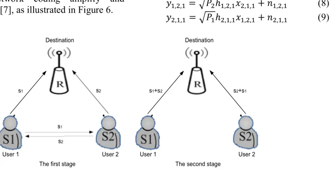
In the PNC, there are also schemes AF (amplify and forward) called with (Pseudo Physical-Layer Network coding amplify and forward (PPNCAF) [7], as illustrated in Figure 6.
As seen in Figure 6, there are two terminal user nodes and the destination node (BS). For PPNCAF scheme, the timeslot 1, user 1 and user 2
transmit two messages that s1 and s2 respectively
using channel coding. Both the messages use orthogonal channels. The timeslot 2, the message is
encoded into s1 + s2 and s2 + s1 using the technique
of pseudo physical-layer network coding in relay node respectively. At the destination node receives four different types of messages that s1, s2, s1+s2,
and s2+s1, each of these four messages experiencing
fading. One of the two messages in the same timeslot with a message in another timeslot can
rebuild two sources, namely message s1 and s2.
Destination node reconstructs the message by MRC (Maximum ratio combining).
PPNCAF schemes can be divided into two stages, namely at timeslot 1 and timeslot 2. The message that is sent from each node can be written by the equation:
𝑦, , = ℎ, , 𝑥, , + 𝑛, , (7)
where :
𝑥, , and 𝑦, , : messages sent and received by
node i
𝑛, , : additive white Gaussian noise;
i = 1,2 : user for transmission 1 and
transmission 2;
j, j ∈ (1, 2,d ) : acceptance by user1, 2 and BS.
k : timeslot
In the first phase, user 1 and user 2 broadcasting messages to one another and also to the destination node respetively, regardless of S-R link quality. Messages received by the second node were written by the equation:
𝑦 , , = 𝑃 ℎ, , 𝑥 , , + 𝑛 , , (8)
𝑦 , , = 𝑃 ℎ , , 𝑥, , + 𝑛 , , (9)
User 1 User 2
Destination
User 1 User 2
Destination
s1
s2
s1 s2 s1+s2 s2+s1
The first stage The second stage
[image:4.612.171.512.537.712.2]5 User Station
Encoding Modulation Channel
Modulation Encoding
Source bits sequence of user 1
Source bits sequence of user 2
User 1
User 2
ChannelRelay and Broadcast phase
Demodulation
Decoding
Modulation Y1 + Y2
Channel Y2
Y1
Destination Network Coding MRC
MRC Network Coding Calculate
information bits of user 2
Calculate information bits
of user 1
Demodulation & Decoding
Demodulation & Decoding
User 1
[image:5.612.97.517.68.298.2]User 2
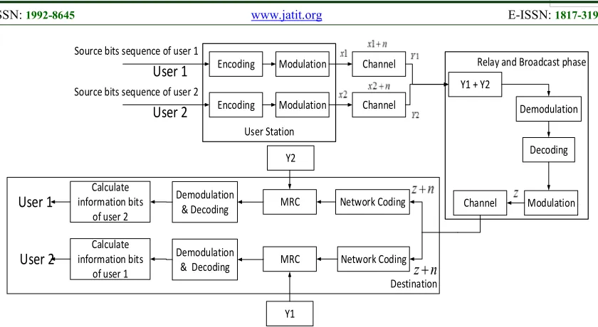
z
n
Figure 7: Model of cooperative communication system with network coding
Where ℎ , , = ℎ , , . User 1 and 2 store the
messages that have been received at each node that has sent each other mutually. Meanwhile, received messages at BS can be written by the equation:
𝑦 , , = 𝑃 ℎ , , 𝑥 , , + 𝑛 , , (10)
𝑦 , , = 𝑃 ℎ , , 𝑥, , + 𝑛 , , (11)
Where P is the power of the received signal (Watt), 𝑥, , = 𝑥 , , =s1, 𝑥 , , =𝑥 , , =s2, and ℎ , , =
ℎ , , . In the second stage in the user 1 and 2
combine each other's messages with other messages by multiplying β factor with techniques pseudo physical-layer network coding. The combination combines the message on the second timeslot is written by the equation:
𝑥 , , = 𝛽𝑦 , , + 𝑠 (12)
𝑥 , , = 𝛽𝑦 , , + 𝑠 (13)
And received messages at the destination node (BS) in the second time slot are:
𝑦 , , = 𝑃 ℎ , , 𝑥 , , + 𝑛 , , (14)
𝑦 , , = 𝑃 ℎ , , 𝑥, , + 𝑛 , , (15)
On the destination node (BS), this message will be processed into:
𝑧 = 𝑦 , , − 𝑦 , , (16)
𝑧 = 𝑦 , , − 𝑦 , , (17)
Taking into account the message transmitted by the user 1, the message processing could follow the method of Maximal-Ratio Combining (MRC), so we get:
ỹ = ∗, ,
, , 𝑦 , , + , , ∗
, , ∗
, , , , , , , , 𝑧 (18)
Since the user 1 combined itself with s1 with
the received message 𝑦 , , in the second stage, in
which a message 𝑦, , is received from the user 2
in the first stage. By processing the message
𝑦 , , and 𝑦 , , were obtained:
𝑧 = 𝑦 , , − 𝑦 , , (19)
2.8 Software Defined Radio
Software Defined Radio (SDR) is a technology that allows to change RF parameters, carrier frequency, modulation type, or output power of a transmitter or radio receiver using a software. Software Defined Radio (SDR) using a digital device that can be programmed to perform signal processing required to send and receive information on radio frequency baseband. Digital devices such as the source signal processor (DSP) and field programmable gate array (FPGA) requires a function for signal processing. SDR can customize with the latest software if it appears a new wireless communication standard.
3.
SYSTEM MODEL6 Gaussian Noise (AWGN). The signals passing through the channnl will be added to the value of the amplitude level of noise in the signal amplitude level.
The difference between the cooperative communication systems with network coding scheme and regular traditional side relay node (without network coding) is a traditional scheme of information received in the relay node will be strengthened and then sent back to the destination without going through the process of decoding. While the scheme of network coding in relay node two pieces of information received at the relay node are summed, then broadcast to each destination
In this paper, after doing system design as well as the results, the next step is done is done of integration between the PC and the device WARP. WARP devices used in research that WARP Lab V.2 with version 7. The integration between the PC and the device WARP using Ethernet switches and LAN cable. The integration between PC and WARP shown in Figure 8.
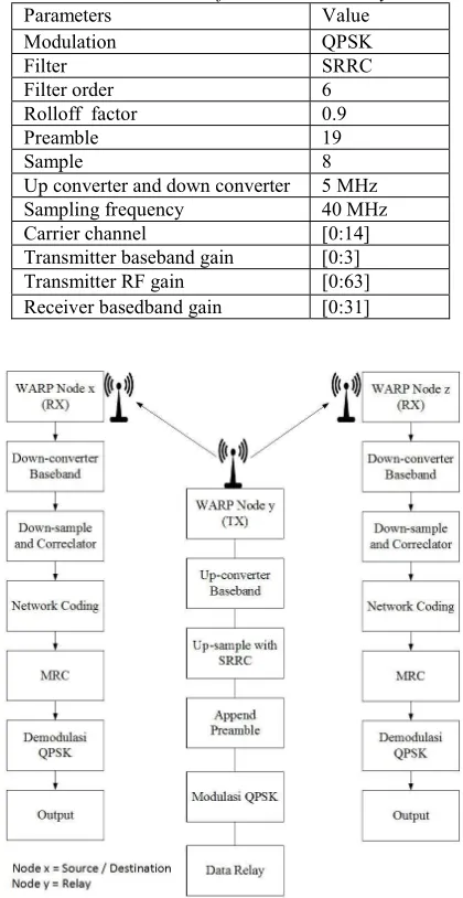
The next step is modeling communication systems. This communication system model uses several parameters based on Table 1.
Implementation of the SIMO communication system in the WARP module requires several stages. The SIMO communication steps with Network coding using WARP are described in figure 9.
In general the block diagram of a cooperative communication system with Network coding is over the source, relay, and destination. Transmission of the system is divided into three types, namely relay transmission, source-destination transmission and relay-source-destination transmission. On the receiver side is calculated BER and throughput.
[image:6.612.313.523.104.511.2]Figure 8: Integration between PC and WARP
Table 1 Parameters of communication system
Parameters Value
Modulation QPSK
Filter SRRC
Filter order 6
Rolloff factor 0.9
Preamble 19
Sample 8
[image:6.612.92.299.542.706.2]Up converter and down converter 5 MHz Sampling frequency 40 MHz Carrier channel [0:14] Transmitter baseband gain [0:3] Transmitter RF gain [0:63] Receiver basedband gain [0:31]
Figure 9: Diagram Block of SIMO communication system
The BER calculation in this paper is done by comparing the received bit with the transmitted bit. The following formula for calculating BER [12]:
𝐵𝑖𝑡 𝐸𝑟𝑟𝑜𝑟 𝑅𝑎𝑡𝑒 = 𝑟𝑒𝑐𝑒𝑖𝑣𝑒𝑑 𝑏𝑖𝑡
𝑡𝑟𝑎𝑛𝑠𝑚𝑖𝑡𝑡𝑒𝑑 𝑏𝑖𝑡 Throughput is the level of success of information sent in a communication channel. In this paper one of the parameters measured is throughput, the equation for calculating throughput is as follows [13-14]:
Number of bits received
7
4.
MEASUREMENT AND ANALISYSThe measurement technique in this research was conducted on two different conditions, namely indoor and outdoor environment with LOS and NLOS conditions [9]. The parameter measured is Throughput of the system. Throughput is an important parameter to indicate the level of performance of a network in packet delivery. The greater the throughput value usually indicates that the performance of a system will be better. Analysis of throughput measurement is done on the condition of indoor and outdoor environment with condition of LOS and NLOS. From this measurement can be used as a scenario of
performance analysis of cooperative
communication system with and without network coding.
4.1 Throughput Analisys in the Indoor Environment
Measurements in indoor environments with LOS conditions are done by changing the function of transmit power level (Tx_Rf) from 0 to 60. Distance between nodes is 4 m, meaning the distance between node 1 to relay 4 m and distance between relay with node 2 is 4 m. The measurement results were used to compare the performance of the cooperative communication system with network coding and without network coding (cooperative).
Figure 10 showed the throughput of the cooperative communication system with and without network coding was directly proportional to the increase in transmit power, but at certain transmit power the relative throughput was constant. Cooperative communication system with network coding produced greater throughput than conventional cooperative communication systems. The percentage increase in throughput for Cooperative communication system with network coding is approximately
=4.8 − 4.19
4.19 𝑥 100% = 14%
The results of throughput measurements on the indoor environment and NLOS condition can be seen in figure 11. Based on Figure 11 showed that the throughput of the cooperative communication system with and without network coding was also directly proportional to the increase in transmit power, but at certain transmit power the relative
throughput was constant. Cooperative
communication system with network coding produced greater throughput than conventional cooperative communication systems. While the percentage increase in throughput for Cooperative communication system with network coding is
approximately.
=4.9 − 4.1
4.1 𝑥 100% = 20%
[image:7.612.322.516.304.463.2]Based on figure 10 and figure 11 showed that the percentage increase in throughput of cooperative communication system with network coding under NLOS conditions was better than LOS.
Figure 10: Throughput in the indoor environment on LOS condition
Figure 11: Throughput in the indoor environment on NLOS condition
-35 -30 -25 -20 -15 -10 -5 0
Gain TX (dB)
2.5 3 3.5 4 4.5 5
[image:7.612.320.517.519.679.2]8
4.2 Throughput Analisys in the Oudoor Environment
The measurement of the system in the outdoor environment was done in the parking lot of the lecturer of the department of electrical engineering, faculty of electrical technology, ITS, Surabaya,
Indonesia [9]. Measurements in outdoor
environments with LOS conditions were also done by changing the function of transmit power level (Tx_Rf) from 0 to 60. Distance between nodes is 4 m, meaning the distance between node 1 to relay 4
[image:8.612.320.523.84.264.2]m and distance between relay with node 2 is 4 m.
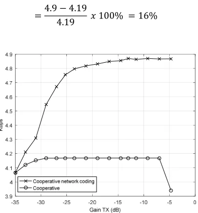
Figure 12 showed cooperative communication system with network coding produced greater
throughput than conventional cooperative
communication systems. The percentage increase in throughput for co-operative communication system with network coding is approximately
=4.9 − 4.19
4.19 𝑥 100% = 16%
Based on Figure 13, it can be seen that the throughput of co-operative communication system with network coding had the value of a good throughput compare with the traditional. With the percentage increase in throughput for network coding scheme is about
=4.9 − 4.19
[image:8.612.96.299.447.666.2]4.19 𝑥 100% = 16%
Figure 12: Throughput in the outdoor environment on LOS condition
Figure 13: Throughput in the outdoor environment on NLOS condition
Based on figures 12 and 13 indicates that the percentage increase in throughput of cooperative communication systems with network coding under NLOS conditions was relatively similar to LOS.
4.3 Synthesis
In the previous article, cooperative
communication system without network coding has been studied. It was studied with both simulation and implementation methods with WARP. This paper shows the performance of cooperative communication systems with and without network coding implemented on WARP.
In the indoor environment, the percentage
increase in throughput of cooperative
communication system with network coding under NLOS conditions was better than LOS. In the outdoor environment, the percentage increase in throughput of cooperative communication systems with network coding under NLOS conditions was relatively similar to LOS.
5.
CONCLUSIONNetwork coding is one technique to improve the throughput of communication systems. In this article carried out the implementation of network coding on cooperative communication system using WARP. Cooperative communication system with and without network coding based WARP was performed system performance measurement. System performance measurements were performed in indoor and outdoor environments, also under LOS and NLOS conditions.
9 condition showed throughput improvement of the cooperative communication system with network coding 14% than without network coding, whereas at NLOS condition 20%. Measurements in outdoor environments under LOS and NLOS conditions show an increase in the throughput of cooperative communication systems with network coding same relative to 16%. From the analysis of measurement results can be concluded network coding able to increase throughput significantly in the indoor environment on NLOS conditions.
6.
ACKNOWLEDGMENTSThis project was financially supported by a Research Grant from the Indonesian government through the ministry of research - technology and higher education with PUPT research scheme.
REFRENCES:
[1]. Rappaport, Theodore S (2002). “Wireless
Communications Principles and Practice” Second edition. Prentice Hall, Inc, Upper Sadley River. New Jersey.
[2]. N. Aria, T. E. Hunter, and A. Hedayat,
“Cooperative Communication in Wireless Network,” Oct-2004.
[3]. Ray Liu, K. J., K. Sadek, Ahmad., Su,
Weifeng., and Kwasinski, Andres., 2009.
Cooperative Communication And
Networking. Cambridge University Press.
[4]. Fragouli, Christina., and Soljanin, Emina.,
2007. Network coding Fundamentals,
Foundation and Trends R in Networking, vol 2, no 1.
[5]. Soung Chang Liew, Shengli Zhang, “Physical
Layer Network coding: Tutorial, Survey And
Beyond”, 2013., Physical Communication 6 4-42.
[6]. https://warpproject.org.
[7]. Xiaoming Liu, et al, “A
Physical-Network-Coding-based Amplify and Forward
Cooperation Scheme”., Harbin. IEEE,
December 2013
[8]. Suwadi, T. Suryani, I. Anisah, "Performance
analysis of cooperative communication systems using wireless open access research platform for indoor and outdoor environment",
Journal of Theoretical and Applied Information Technology, Vol.83, No.3, January, 2016, pp. 474-481.
[9]. Endroyono, Suwadi, Achmad Ansori, Ummul
Khair, “Implementation of wireless
communication system using network coding
on WARP”, Journal of Theoretical and
Applied Information Technology, Vol.95, No.8, April, 2017, pp. 1745-1753.
[10].W Peter Hong, Wan Jen Huang, C.C Jay Kuo,
“Cooperative Communication And Networking”, Technology And System Design, 2010.
[11].Zhanji, Wu. et. Al., 2012. A Physical-layer
Network coding Relay scheme for IEEE 802.11.
[12].Proakis, John G., Masoud Salehi., “Digital
Communications”, The McGraw-Hill Companies, Inc., USA, 2008.
[13].Sklar, Berhard, “Digital Communications