TRAFFIC LIGHT MANAGEMENT SYSTEM BASED ON
HAMILTONIAN ROUTING TECHNIQUE
1ADNAN A. HNAIF, 2AMNAH EL-OBAID AND 3NANCY AL-RAMAHI
1
Faculty of Science and Information Technology, Al-Zaytoonah University of Jordan, Departmentof
Computer Network, Jordan 2
Faculty of Science and Information Technology, Al-Zaytoonah University of Jordan, Department of
Computer Network, Jordan 3
Faculty of Science and Information Technology, Al-Zaytoonah University of Jordan, Department of
Computer Information System, Jordan
E-mail: [email protected], [email protected],[email protected]
ABSTRACT
Traffic congestions are recognized as a major problem in the modern urban cities. The Hashemite Kingdom of Jordan is considered as one of the top countries worldwide that is suffering from the traffic jam problem due to its old infrastructure. The current traffic light signals system in Jordan is still controlled by the fixed timers. Therefore, this research develops an intelligent Traffic Light Management System Based on the Hamiltonian Routing Technique (TLBH) and on the Decision Support System (DSS) in order to execute a proper action. Hence, this research develops a system can that be used to minimize the waiting time on the traffic signals for vehicles, which can in return lead to the reduction of the traffic congestion incurred by the vehicles.
This research is comprehensive to many scenarios, where three of these scenarios are listed in this research and are implemented by the system by using the MATLAB programming language; based on specific rules. According to these sufficient testing scenarios, the simulation result shows significant improvements in the TLBH technique in comparison with the current traffic system. The proposed technique has the minimum total and waiting time in all scenarios compared to the current traffic system.
Keywords:Traffic light management system, routing protocols, Hamiltonian routing technique.
1. INTRODUCTION
In the past ten years ago, the number of vehicles in the Hashemite Kingdom of Jordan has been rapidly growing considerably, taking into account that the infrastructure remained unchanged. Accordingly, traffic congestions have become a big burden on the goers, particularly, in the peak times of the traffic load.
However, the definition of the traffic congestion is still debatable, some researchers’ categories the traffic congestion into three categories: capacity concerning, delay time, and cost related. The traffic congestion is based on the capacity that is concerned on what happened when the number of vehicles exceeds the road capacity. On the other hand, the delay time occurs when the traffic goes at a speed that is less than the road
capacity, or the delay along the way due to the presence of the vehicles [1]. The cost related is the interference among all road drivers, which leads to increase the traffic congestion [2].
On the other hand, the traffic congestion problem costs millions of dollars of wasted fuel, because unjustified waiting time on the traffic signal works by either giving each individual traffic light fixed timer, or by using weight plates. Other problems may occur due to the traffic congestion, such as: the loss of time, the increase of the time that is required to pass emergency vehicles, etc. [3].
and the effectiveness of the traffic light system, more studies and researches are genuinely needed for the next upcoming years; otherwise the problem will worsen an increased fuel consumption, and therefore, increasing the environmental pollution.
In fact, the current traffic light system in Jordan is still using a fixed timers system, meaning that every single light signal is assigned by a fixed timer regarding to the number of vehicles.
Many researches have been conducted in order to enhance the performance of the traffic light system. Thus, the aim of this research is to enhance the performance of the traffic light system for a whole city by using the Hamiltonian routing technique and the DSS. Hamiltonian routing technique is a technique that can be used to partition the network into sub networks (Mesh topology), in order to connect the source node with multiple destination nodes, by selecting the shortest path, and also to guarantee that the deadlock problem will never occur. When the entire destination nodes have now received their information, the DSS will execute the proper action based on the collected information.Thus, the main contribution of this research is to minimize the total waiting time on the traffic signals for vehicles. Hence, reducing the traffic congestion, saving time, and reduce fuel consumption.
2. LITERATURE SEARCH
In this section, the most important routing protocols, and the more closely related works of the traffic light system are presented.
2.1 Routing Protocols
2.1.1 Routing information protocol (RIP) The RIP is a distance vector protocol, which usually updates its routing table every thirty seconds. In particular, each router maintains its routing table that can communicate with its neighboring routers. In addition, the RIP is a standout amongst the most normally utilized steering conventions for little homogeneous systems. As a separation vector directing convention, the RIP is utilized by switches in order to trade the topology data intermittently by conveying steering table points of interest to neighboring switches at regular intervals [4]. The maximum range of jumps in the RIP is 15 jumps, which makes it inappropriate for large and complex networks [5].
On the other hand, RIP has more routing loops, very slow, and does not solve the deadlock problem [6].
2.1.2 Open shortest path first OSPF (OSPF) The OSPF is a link state routing protocol of where every router works severally in order to calculate its own shorter route towards the destination by using the Dijkstra algorithm. The update is usually caused by a modification within the topology of the network, and leads to rapidly re-establish it if the route comes without loops. In particular, the OSPF is designed for the networks with a constant growth, and is able to handle the distributed routing table for a quick propagation. The main advantage of the OSPF is that the presence of the subnet and the super-net masks along with the provision of the authentication [7].
The disadvantage of the OSPF is that more routers are added to the networks. This implies that several copies of the routing information will be added to the network, and hence, it will increase the traffic in every single operation a router sends the information. Consequently, this makes the OSPF unsuitable for large networks [6].
2.1.3 Enhanced interior gateway routing protocol (EIGRP)
The EIGRP or the enhanced IGRP is a Cisco restrictive directing convention that makes use of the Diffusing Update Algorithm (DUAL) [8]. The EIGRP is a cross breed convention as it consolidates the components of a distance vector by steering the convention and the elements of a link state directing convention. The Improved Interior Gateway Routing Protocol (EIGRP) is an upgraded adaptation of the IGRP. The Enhanced Interior Gateway Routing Protocol (EIGRP) is a half breed directing convention, which produces huge changes on the IGRP. In spite of the advantages of the EIGRP, it also has one limitation that increases the traffic congestion, which is caused by sending information during an allotted time from the neighboring routers in order to query for the information again [6].
2.1.4 Hamiltonian routing technique
The deadlock problem in any interconnection network occurs when no message can advance towards to its destination since the queue of the messages system is full. No communication can
occur over the deadlocked channels until
destination node. The destination node(s) which is directly connected with the source node can be easily visited by selecting the shortest path, where it will guarantee that the deadlock is really free (Hamiltonian routing technique is discussed in detail in Section 3).
2.2 Related Works
Many researchers have been carried out for the general problem of the traffic lights system. As previously mentioned, the number of vehicles in Jordan has rapidly increased in the last few years, which led to the increase in the number of traffic causing many severe traffic issues, such as the
increase in fatalities and injuries [11].
Unfortunately, Jordan is considered as one of the top countries worldwide in terms of the frequency of traffic incidents, as was pointed out by [12]. In addition, the current traffic light signals system in Jordan is still using a fixed timers system. In other words, the vehicles that stop when the red traffic light sign is set on, have to wait for a fixed amount of time, while some other traffic lights in the same intersection is empty.
In [13], a system that can be used to route all the update information about the traffic flow in the intersection via any smart phone application to reduce the traffic congestion is proposed. When the details are received to the other entire traffic lights, the DSS will be used to manipulate the traffic congestion problem if it occurs.
Other researchers as in [14] make use of the genetic algorithm in order to select the optimal traffic performance for intersections. The proposed system shows an advantage over the traditional fixed timer traffic light system. On the other hand, [15] uses the Global Positioning Service (GPS) in order to determine the location and time information of the vehicles in all weather conditions. In addition, [16] uses the laser tracker technology in order to track the vehicles by measuring their distance, where the reflected laser beam with laser interferometer can be used to find the distance between the vehicles (traffic between objects). In fact, this system works efficiently in a stable environment, but in real time, it is difficult to track multiple objects, instead of it is very expensive and hence not used usually.
Other researches as in [17] [18] use cameras to monitor the traffics. Cameras can be used to monitor and to remotely control large areas. Nonetheless, cameras are used to count and speed
measurements, but large numbers of cameras are needed to be covered for a long distance. Hence, cameras are suitable to monitor the intersections only.
Alternatively, cameras are Infrared devices that are used under exceptional circumstances. An infrared device has less consumption power, and hence, cost effective [19]. Moreover, [20] uses another tracking system called the Radio Frequency Identification (RFID), which identifies the type of vehicles, and then, can predict the number of vehicles in an accurate manner.
In [3], an intelligent traffic control system with the concern on many parameters is proposed. In particular, these parameters comprise; the number of vehicles, emergency vehicles, and times peak traffic road, the accidents, and any closing path. The proposed system depends on the approximate number of vehicles based on the time period for which the traffic light must be opened. Depending on the area vehicles, which can be calculated as the sum of the illuminated areas that are divided by the total road area, a certain threshold is calculated, and then, this threshold makes the system send a signal to in order to increment or to decrement the time period for the intersection circle. Further, the emergency vehicles have the maximum priority compared to other system factors.
3. THE PROPOSED TLBH AND ITS IMPLEMENTATION
The current traffic light system used in Jordan is still working by giving fixed timer to each traffic light without taking any considerations about the number of vehicles at each individual traffic light. On the other hand, each intersection is working separately or individually, where this leads to increase the traffic jam in a whole city. The proposed Traffic Light Management System Based on Hamiltonian (TLBH) technique copes up with this problem by connecting the whole city as a mesh topology, where each node denotes to an intersection. In addition, each node represents a source or a destination intersection, and therefore, every intersection will send its information to the entire neighbors, which are directly connected with the source node, and will guarantee the deadlock problem will never happen.
Hamiltonian labeling system, each intersection in the city will be assigned by a unique number based on the coordination of the intersection on the network. Suppose that the city represents the (‘x’ בy’) coordinates, where ‘x’ represents the number of rows, and ‘y’ represents the number of columns, then the label assignment function ‘L’ can be expressed in terms of the ‘x’, ‘y’ coordinates of each intersection as follows:
‘x’ * ‘c’ + ‘y’ if x is even
L(x,y)= (1)
‘x’ * ‘c’ + ‘c’ –‘y’ – 1 if x is odd
Refer to figure 1, and figure 2 the labeling function ‘L’ applied to assign a unique number of each intersection as follows: suppose that the network represents a (4 × 4) 2D mesh topology (c=4), to calculate L(x=0, y=0), then to apply (‘x’ × ‘c’ + ‘y’) formula, because ‘R’ is even, the result obtained (0 × 4 + 0 = 0). Hence, the first intersection will be assigned by number 0 (refer to figure 1); and also to assign a number to the intersection of L(x=3, y=1) in the same figure, then apply (‘x’ × ‘c’ + ‘c’ – ‘y’ – 1) formula, because ‘R’ is odd, the result is (3 × 4 + 4 – 1 – 1 = 14). Hence, the intersection will be assigned by number 14, and so on.
Consequently, suppose that ‘S’ represents the source node, and ‘D’ represents the destination node(s). The TLBH technique will act as follows:-
Step 1: If L (‘R’, ‘C’)=0, then, it will send its information (the name of traffic light, the number of vehicles on the traffic light, the expected number of vehicles from all neighbors, the total number of vehicles, time, road speed and road capacity) to the neighboring node(s) directly without applying the routing function ‘R’. Otherwise go to step 2.
Step 2: The source node divides ‘D’ into
two subsets: D Upper (DU) and D Lower (DL)
where:DU contains the entire nodes that the label
numbers are greater than the label number of the
source node. DL contains the entire nodes that the
label numbers are less than the label number of the source node.
Step 3: The source node sorts the subset DU in an ascending order, and DL in a descending order.
Step 4: The source node ‘S’ sends its information to the destination nodes ’D’ by using the following routing function: R (‘S’, ‘D’) = ‘N’, where ‘N’ represents the neighboring selected nodes of ‘S’. The routing function R can be expressed in the following equations as:
DU: L(N)=max{L(N)|L(N)≤1staddress € L(DU)} (2)
DL: L(N)=min{L(N)|L(N)≥1staddress € L(DL)} (3)
Step 5: Each selected node (‘N’), checks its address with the first address of the destination
nodes (DU and DL), if equal, then this selected node
will remove its address from the destination node. Then, it will make a copy of the information and send it to the neighboring nodes by using the routing function R. Otherwise; it will send the information to the neighboring nodes by using the routing function R.
Step 6: Repeat from Step 4, until all destination nodes are visited.
The Hamiltonian routing technique is ideal for this issue since it is considered a free deadlock problem. The deadlock problem will occur when there is a cyclic dependency among the source nodes. Each source node ‘S’, divides the destination
nodes ‘D’ into two subsets: DU and DL. The
information will be sent to the destination nodes in
DU and DL simultaneously by using the routing
function R. The subset DU always sends the
information from lower label nodes to higher label
nodes. While the subset DL always sends the
information from higher label nodes to lower label nodes. Therefore, no cyclic dependency may occur among the source nodes (refer to figure 3 and figure 4).
Figure 1: 4 x 4 mesh topology
14 15
11 10
9 8
7 6 5 4
3 2
1 0
13 12
[image:4.612.342.492.565.706.2]Figure 2: 4 x 3 mesh topology
Figure 3: path for DU
Figure 4: path for DL
4. RESULTS AND BUSINESS PROBLEM
In order to illustrate the implementation of the TLBH technique, consider a network size of 4x4 2D mesh topology (refer to figure 5).
Case 1: The source node 0 (startup point) send its information directly to the destination nodes {1, 7} without applying the routing function R. The routing path can be shown in a purple color.
Case 2: Select any other source nodes, such as 6; hence, the destination nodes which are directly connected with Node 6 are {5, 7, 9, and 1}.
The TLBH technique divides the destination
nodes into two subsets; DU and DL. DU contains the
entire nodes, which label the numbers that are higher than the label node 6. The DU = {7, 9}. In
addition, the DL contains the entire nodes, which
label the numbers that are lower than the label node
6. The DL = {5, 1}.
The subset DU sorts its nodes in an ascending
order, and the subset DL sorts its nodes in a
descending order. DU= {7, 9} and DL= {5, 1}.
In order to determine the path, the TLBH technique must use the routing function ‘R’ for the
two subsets DU and DL as follows:
A. For the subset DU:
The path L (W) = max L (9 and 7), where the maximum label number should be smaller than or equal to the label number of the first node in the
subset DU which is 7. Hence the TLBH technique
will select the path through Node 7, and will also
remove this destination node from the subset DU,
where the subset DU = {9}.
In Node 7, the TLBH technique will select the path via Node 8; because there is no another node that has a label number greater than the source label of Node 6.
In Node 8, the TLBH technique repeats the routing function L (W) = max L (15 and 9), where the maximum label number should be smaller than or equal to the label number of the first address in
the subset DU, which is 9. Hence, the TLBH
technique will select the path through Node 9, and will also remove this destination node from the
subset DU. Note that all destination nodes in the
subset DU have been visited, and the subset DU
became empty.
B. For the subset DL:
In order to select the path, L (W) = min L (5 and 1), the minimum label number should be greater than or equal to the label number of the first
address in the subset DL which is 5. Hence, the
TLBH technique will select the path through Node 5, and will also remove this destination node from
the subset DL, the subset DL = {1}.
0, 0 0, 1 0, 2
1, 0 1, 1 1, 2
2, 0 2, 1 2, 2
3, 0 3, 1 3, 2
10 11
8 7
6
5 4 3
2 1
0
9
0 1 2
5 4 3
6 7 8
11 10 9
0 1 2
5 4 3
6 7 8
In Node 5, the TLBH technique repeats the routing function L (W) = min L (4 and 2), where the minimum label number should be greater than or equal to the label number of the first address in the
subset DL, which is 1. Accordingly, the TLBH
technique will select the path of Node 2.
In Node 2, the TLBH technique repeats the routing function L (W) = min L (3 and 1), where the minimum label number should be greater than or equal to the label number of the first address in the
subset DL, which is 1.The TLBH technique will
select the path through Node 1, and will also
remove this destination node from the subset DL.
Note that the entire destination nodes in the subset
DL have been visited, and the subset DL became
empty (the routing path of this case can be shown in a black color).
Another case can be presented when the source node have three destination nodes, such as Node 11. The source node 11 has three destination nodes {12, 4, and 10}.The TLBH technique apply
the same previous steps, and hence, the subset DU =
{12}, and the subset DL= {4, 10} (the routing path
of this case can be shown in yellow color).
[image:6.612.90.285.435.579.2]In order to assign a dynamic timer for each traffic light round, the DSS will apply the following equation:
Figure 5: The TLBH technique routing function
60*0.75 if no. of cars > 60
40*0.5 if 40≤ no.of cars ≤60
T= (4)
no. of cars * 0.5 if no. of cars < 40
0 if no.of cars=0
Where, 40 represents normal traffic jam, and 60 represents real traffic jam. In addition, 0.5 and 0.75 represent the time required to pass only one vehicle in both cases.
Each traffic light assigns its priority number according to the number of vehicles that are waiting on it. Accordingly, every traffic light will take its round based on its priority number. This case is called the normal case. Another special case happened when one or more traffic lights are waiting on its priority number for more than two rounds without taking any round.
In this case, the DSS will stop applying the priority number sequences, and the priority will be given directly to the traffic light, which has stopped for more than two rounds. After the special case has finished, the normal case will be applied again, and the number of rounds is set to zero (refer to table 2, where T.L.: Traffic Light, N.C.: Normal Case, S.C.: Special Case, V.: Vehicles, R.V.: Remaining Vehicles, I: Intersection).
In addition, if the number of vehicles at the Intersection ‘a’ is greater than 60 vehicles, then the timer assigned to it is (60 x 0.75) seconds. Besides, the vehicles will pass into another Intersection ‘b’ with ‘n’ number of vehicles. If the total number of vehicles exceeds the capacity road between these two intersections, then the timer on the Intersection ‘a’ will stop to avoid the jam, which may occur at Intersection ‘b’, and which may give the priority round into another traffic light at Intersection ‘a’.
Tracing example
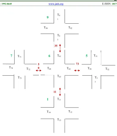
Consider the following intersections (refer to table 1).
Table 1: Intersections with their traffic lights information
Where n denotes to any number of vehicles, and figure 6 illustrates table 1 in depiction.
# of traffic lights =4 and # of lanes =3
Inter-section Name Names # of vehicles
6 T6 T61, T62, T63 ,T64 20, 43, 6, 40 9 T9 T91, T92, T93 ,T94 n, n, 15, n 5 T5 T51, T52, T53 ,T54 n, n, n, 30 7 T7 T71, T72, T7 ,T74 n, 10, n, n 1 T1 T11, T12, T13 , T14 5, n, n, n
7 5 4
0 1 2 3
8 10 11
15 14 13 12
9
6 Sour
Figure 6: The illustration depiction of intersections with their information
6
T11
T12 T14
T13
T51
T52 T54
T5
3 T71
T72 T74
T73
T9
1
T92 T94
T9
3
T61
T62 T64
T63
9
7
5
1
11 5
0
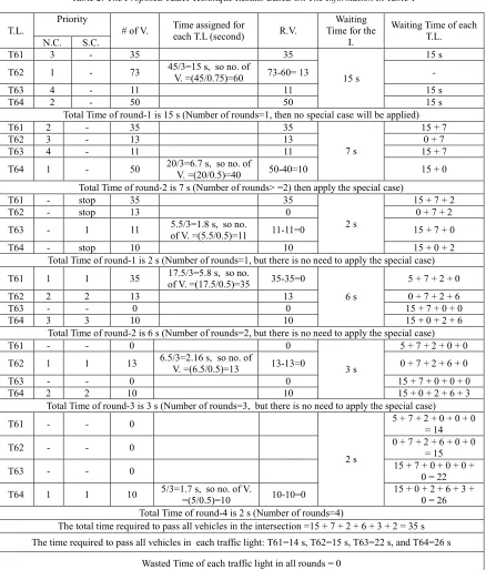
Table 2: The Proposed TLBH Technique Results Based On The Information In Table 1
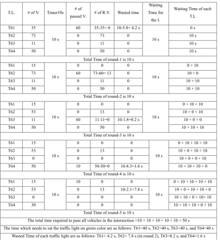
The result of the current used system in Jordan (refer to table 3), where each traffic light has a fixed timer =10 seconds, regarding to the number of vehicles that are stopped or waiting at the traffic light.
T.L.
Priority
# of V. Time assigned for
each T.L (second) R.V.
Waiting Time for the
I.
Waiting Time of each T.L. N.C. S.C.
T61 3 - 35 35
15 s
15 s T62 1 - 73 45/3=15 s, so no. of
V. =(45/0.75)=60 73-60= 13 -
T63 4 - 11 11 15 s
T64 2 - 50 50 15 s
Total Time of round-1 is 15 s (Number of rounds=1, then no special case will be applied)
T61 2 - 35 35
7 s
15 + 7
T62 3 - 13 13 0 + 7
T63 4 - 11 11 15 + 7
T64 1 - 50 20/3=6.7 s, so no. of
V. =(20/0.5)=40 50-40=10 15 + 0 Total Time of round-2 is 7 s (Number of rounds> =2) then apply the special case)
T61 - stop 35 35
2 s
15 + 7 + 2
T62 - stop 13 0 0 + 7 + 2
T63 - 1 11 5.5/3=1.8 s, so no.
of V. =(5.5/0.5)=11 11-11=0 15 + 7 + 0
T64 - stop 10 10 15 + 0 + 2
Total Time of round-1 is 2 s (Number of rounds=1, but there is no need to apply the special case) T61 1 1 35 17.5/3=5.8 s, so no.
of V. =(17.5/0.5)=35 35-35=0
6 s
5 + 7 + 2 + 0
T62 2 2 13 13 0 + 7 + 2 + 6
T63 - - 0 0 15 + 7 + 0 + 0
T64 3 3 10 10 15 + 0 + 2 + 6
Total Time of round-2 is 6 s (Number of rounds=2, but there is no need to apply the special case)
T61 - - 0 0
3 s
5 + 7 + 2 + 0 + 0 T62 1 1 13 6.5/3=2.16 s, so no. of
V. =(6.5/0.5)=13 13-13=0 0 + 7 + 2 + 6 + 0
T63 - - 0 0 15 + 7 + 0 + 0 + 0
T64 2 2 10 10 15 + 0 + 2 + 6 + 3
Total Time of round-3 is 3 s (Number of rounds=3, but there is no need to apply the special case)
T61 - - 0
2 s
5 + 7 + 2 + 0 + 0 + 0 = 14
T62 - - 0 0 + 7 + 2 + 6 + 0 + 0
= 15
T63 - - 0 15 + 7 + 0 + 0 + 0 +
0 = 22 T64 1 1 10 5/3=1.7 s, so no. of V.
=(5/0.5)=10 10-10=0
15 + 0 + 2 + 6 + 3 + 0 = 26 Total Time of round-4 is 2 s (Number of rounds=4)
The total time required to pass all vehicles in the intersection =15 + 7 + 2 + 6 + 3 + 2 = 35 s The time required to pass all vehicles in each traffic light: T61=14 s, T62=15 s, T63=22 s, and T64=26 s
Table 3: The Results Of The Traffic Light System That Are Used In Jordan Based On The Information Of Table 1.
T.L. # of V. Timer10s # of
passed V. # of R.V. Wasted time
Waiting Time for the I.
Waiting Time of each T.L
T61 35
10 s
60 35-35= 0 10-5.8= 4.2 s
10 s
0 s
T62 73 0 73 0 10 s
T63 11 0 11 0 10 s
T64 50 0 50 0 10 s
Total Time of round-1 is 10 s T61 15
10 s
0 0 0
10 s
0 + 10
T62 73 60 73-60= 13 0 10 + 0
T63 11 0 11 0 10 + 10
T64 50 0 50 0 10 + 10
Total Time of round-2 is 10 s T61 15
10 s
0 0 0
10 s
0 + 10 + 10
T62 53 0 13 0 10 + 0 + 10
T63 11 60 11-11=0 10-1.8=8.2 s 10 + 0 + 0
T64 50 0 50 0 10 + 10 + 10
Total Time of round-3 is 10 s T61 15
10 s
0 0 0
10 s
0 + 10 + 10 + 10
T62 53 0 13 0 10 + 0 + 10 + 10
T63 0 0 0 0 10 + 0 + 0 + 10
T64 50 10 50-50=0 10-8.3=1.6 s 10 + 10 + 10 + 0
Total Time of round-4 is 10 s T61 15
10 s
10 0 0
10 s
0 + 10 + 10 + 10 + 10
T62 53 0 13 10-2.1=7.8 s 10 + 0 + 10 + 10 + 0
T63 0 0 0 0 10 + 10 + 0 + 10+ 10
T64 30 0 0 0 10 + 10 + 10 + 0 + 10
Total Time of round-5 is 10 s
The total time required to pass all vehicles in the intersection =10 + 10 + 10 + 10 + 10 = 50 s
The time which needs to sat the traffic light on green color are as follows: T61=40 s, T62=40 s, T63=40 s, and T64=40 s Wasted Time of each traffic light are as follows: T61= 4.2 s, T62= 7.8 s (in round 2), T63=8.2 s, and T64=1.6 s
5. DISCUSSION OF THE TLBH PERFORMANCE
Refer to table 4, the TLBH technique has some advantages over the current system that is used in Jordan, particularly, in the time assigned to each traffic light. On the other hand, the TLBH technique has no wasted time in all cases, even
though the number of rounds is greater than the number of rounds in the current used system.
In this paper, an intelligent traffic light management system based on the Hamiltonian routing technique called TLBH is proposed, in order to increase the performance of the traffic light and its efficiency. We have applied the proposed technique and compared the results with the current used system in Jordan. The results show good performance and more efficiency in the TLBH technique. The proposed system (TLBH) technique in all scenarios has the minimum total and waiting time than the current traffic system. That leads, TLBH technique is more efficient than the current used traffic system. The limitation of this research
is summarized in the total cost needed to implement the proposed system.
ACKNOWLEDGMENT
[image:10.612.90.524.294.385.2]We would like to thank Al–Zaytoonah University of Jordan - Faculty of Science and Information Technology for supporting this work.
Table 4: Shows The Comparison Summary Results Between The TLBH Technique, And The Current Used System In Jordan.
Total Time required to pass all vehicles in the intersection
( in seconds)
The time required to pass all vehicles in each traffic light (in seconds)
Number of Rounds
Wasted time ( in seconds)
TL BH
Current used system
TLBH Current used system
TLB H
Current used system
TLB H
Current used system T61 T62 T63 T64 T61 T62 T63 T64
35 50 14 15 22 26 40 40 40 40 6 5 0 21.8
REFERENCES
[1] P.M. Xavier, RajuNedunchezhian, “A
COMPARATIVE STUDY ON ROAD
TRAFFIC MANAGEMENT SYSTEMS”,
International Journal of Research in
Engineering and Technology (IJRET), Vol.3, No.15, 2014
[2] MdAftabuzzaman , “Measuring traffic
congestion- A critical review”, 30th
Australasian Transport Research
Forum(ATRF), Vol.30, 2007
[3] MuzhirShaban Al-Ani1 and KhattabAlheeti,
“INTELLIGENT TRAFFIC LIGHT
CONTROL SYSTEM BASED IMAGE
INTENSITY MEASURMENT”, The 12th
International Arab Conference on Information Technology Naif Arab University for Security
Sciences (NAUSS), 2011
[4] Ahmad Karim, Minhaj Ahmad Khan,
“Behaviour of Routing Protocols for Medium
to Large Scale Networks”, Australian Journal
of Basic and Applied Sciences, Vol. 5, No. 6, 2011, p.p. 1605-1613
[5] Wu, Bing, “Simulation Based Performance
Analyses on RIP, EIGRP and OSPF Using
OPNET”, Math and Computer Science
Working Papers, Vol. 11, 2011
[6] Mr. R. Jayaprakash, 2Ms. K. Saroja, RIP,
OSPF, “EIGRP ROUTING PROTOCOLS,
INTERNATIONAL JOURNAL OF
RESEARCH IN COMPUTER
APPLICATIONS AND ROBOTIC”S, Vol.3,
No. 7, 2015, p.p. 72-79
[7] Archana C, Analysis of RIPv2, OSPF, “EIGRP
Configuration on router Using CISCO Packet
tracer”, International Journal of Engineering
Science and Innovative Technology (IJESIT), Vol.4, No.2, 2015
[8] Vishal sharma, Rajneesh Narula and Sameer
khullar, “Performance Analysis of IEEE 802.3 using IGRP and EIGRP Routing Protocols”,
International Journal of Computer
Applications (0975 – 8887), Vol. 44, No.13, 2012.
[9] Amnah El-Obaid1 and Nagham_Al-Mad,
“Y-HAMILTONIAN LAYERS BROADCAST
ALGORITHM” , International Journal of
Network Security & Its Applications (IJNSA), Vol.8, No.3, 2016
[10] Amnah El-Obaid, “Three-Dimension
Hamiltonian Broadcast Wormhole-Routing”, International Journal of Computer Networks
& Communications (IJCNC),Vol.7, No.3,
[11] S. M. Odeh A. M. Mora, M. N. Moreno, and J. J. Merelo, “A Hybrid Fuzzy Genetic Algorithm f or an Adaptive Traffic Signal
System”, Advances in Fuzzy Systems",
Hindawi Publishing Corporation, 2015
[12] Al-Khateeb, Obaidat, and Khedaywi,
“ROAD SAFETY STRATEGIES
THROUGH EXCELLENCE IN SERVICES,
AWARENESS, AND LAW
ENFORCEMENT IN JORDAN”,
Proceedings of the 5th International Safety Conference on Road and Traffic Safety Strategies, 2008, p.p. 2-1
[13] Santwana Panda Anjali M. Patki, “Edge
Detection Based Traffic Management System with Route Updates on Android Application”, international journal of innovative research in electrical, electronics, instrumentation and control engineering, Vol.4, No.6, 2016.
[14] Leena Singh, “SudhanshuTripathi,
HimakshiArora, Time Optimization for Traffic Signal Control Using Genetic
Algorithm”, International Journal of Recent
Trends in Engineering, Vol.2, No.2, 2009
[15] Jie Du , Barth M.J., Next-Generation
“Automated Vehicle Location Systems:
Positioning at the Lane Level” , IEEE
Transactions on Intelligent Transportation Systems, Vol.9, No.1, 2008
[16] Huijing Zhao Key , Chiba Masaki; Shibasaki
R.; Shao Xiaowei; JinshiCui;HongbinZha , “A Laser-Scanner- Based Approach Toward Driving Safety and Traffic Data Collection”,
IEEE Transactions on Intelligent
Transportation Systems, Vol.9, No.1, 2009
[17] Rong Ding, ShunliWang, and Xu Liu, “Using
Traffic Light Signal to Enhance Intersection Foreground Detection Based on Video Sensor
Networks”, International Journal of
Distributed Sensor Networks, 2014
[18] P. Kumar; S. Ranganath; Huang Weimin; K.
Sengupta, “Framework for real-time behavior
interpretation from traffic video”, IEEE
Transactions on Intelligent Transportation Systems, Vol.6, No.1, 2005
[19] B.N.Nelson, “Automatic vehicle detection in
infrared imagery using a fuzzy
inference-based classification system” , The IEEE
Transactions on Fuzzy Systems (TFS), Vol.9, No.1, 2001
[20] Hongzi Zhu, Shanghai Minglu Li, Yanmin
Zhu, Ni L.M, “HERO: Online Real-Time
Vehicle Tracking”, IEEE Transactions on