Distributed Deadlock Detection using Fault Informing
Probes
V. Geetha
Department of Information Technology Pondicherry Engineering College
Puducherry, India
N. Sreenath
Department of Computer science & Engineering Pondicherry Engineering College
Puducherry, India
ABSTRACT
The existing probe based distributed deadlock detection algorithms work only in fault free environments. But any network is prone to failures. So the existing probe based algorithms fail in such fault prone environment. This algorithm modifies the existing probe based algorithm to adapt in faulty environment also.
General Terms
Distributed Systems, fault tolerance, deadlocks.
Keywords
Distributed Systems, fault tolerance, deadlocks, probe based detection.
1.
INTRODUCTION
Distributed system is a collection of sites that maintains data resources and allows concurrent transactions to work on these data resources. The data resources in each site are managed by resource manager. In each site, a transaction manager is present to manage the transactions arriving in that site. In a truly distributed system, the transactions and resource managers of different sites have to communicate through messages. The main advantage of distributed systems is resource sharing. A transaction may need one or more resources to complete its execution. The required resources may be local or remote to the transaction. Several transactions are allowed to simultaneously access the resources to promote concurrency. But it might affect the consistency of data resources. The concurrency control algorithms are applied to protect the consistency of the data resources. These concurrency control algorithms might introduce deadlocks in transaction execution.
The most popular algorithm for distributed deadlock detection and resolution is probe based algorithm by Chandy and Mishra[7]. In this algorithm, the transaction that suspects deadlock (called initiator) sends probe messages along the wait for edges in the transaction wait for graph. If the probe returns back to the initiator, it indicates the presence of deadlock. Simultaneous initiation of probe messages for same deadlock may lead to phantom deadlocks. Hence priority based algorithms [3, 5, 6] have been proposed. These algorithms ensure that only one probe is sent per deadlock cycle. The initiator is decided based on priority. Later several DDDR (Distributed Deadlock Detection and Resolution) algorithms have been proposed for request models like AND,
OR and generalized models. They optimize on communication and message complexities.
All these algorithms expect the underlying system model to be fault free. But in distributed systems, failures are bound to happen. In Ozu and Valduriez [2], it is stated that the failures in distributed systems could be categorized as:
1. Transaction failure- bug in code
2. Site failure- processor failure
3. Link failure- communication link failure
Though fault diagnosis is not part of deadlock detection, information about faulty sites needs to be given to avoid unnecessary wait time. Unnecessary wait time leads to slower response time and deadlocks.
In Li and Mcmillin [1], a totally distributed fault tolerant DDDR algorithm is proposed using fault diagnosis model. In this the processors are categorized into faulty and non faulty. All non faulty processors will certify the other processors as faulty or non faulty.
A fault vector is attached as part of the probe where each bit in the vector represents a processor in the system. 0 represents non faulty and 1 represents faulty.
This paper has the following drawbacks: The processors are diagnosed periodically by the other non faulty processors. If the period is very small, the non faulty processors need to spend more time in diagnosing other processors than executing their transactions. This will reduce throughput of the system. On the other hand, if the periodicity is more, then reliability reduces. Hence the success of this algorithm lies in choosing ideal period of diagnosis. Message complexity is more in propagating updated processors’ status and clean messages. It can identify only one processor failure per deadlock cycle.
2.
MOTIVATION
The present day distributed systems are prone to failures. So fault tolerance algorithms are needed to improve the reliability and performance. Though there are several fault tolerance algorithms for distributed systems, generally it is not expected by DDDR algorithms to provide fault tolerance. Hence much research work is not done in this area. However the DDDR algorithm should facilitate the initiator to infer why the probe does not come back to it. It might be due to live lock or site failure (where deadlock may be present). If it is due to live lock, then the transactions can wait for finite time and then start sending resources’ requests again. If the probe does not come back due to site failure, then the system needs to be reconfigured to continue. But if it is actually due to deadlock, and probe does not return to initiator due to site failure, then it is a serious problem.
Since there is no ideal fault tolerance algorithm and site failures are bound to happen, the initiator needs to get the probe back always despite whether it is live lock or dead lock. Hence this paper aims to propose a fault informant algorithm that sends colored probes to initiator indicating the sites’ status. It detects at most two site failures per deadlock cycle. In Geetha and Sreenath [11], an algorithm was proposed for detecting probes lost due to faulty environments. In this paper, the algorithm is extended with implementation and proofs. The proposed algorithm uses the following colors in probe messages to indicate the status.
RED: Indicates deadlock and there is no site failure.
ORANGE: Indicates site failure. In this deadlock/ live lock status is unknown due to site failure.
WHITE: Indicates live lock and there is no site failure
In the proposed algorithm, transaction uses forward and backward probe messages to detect the reason for not getting the resource. Initially the color of the probe message is RED. The definitions of forward and reverse probe messages and other messages are given in section 3. A faulty vector is maintained in which each processor is represented by a bit. Bit 1 indicates the corresponding processor is faulty. Bit 0 indicates the site is not faulty. The messages travel along the wait for edges and on the opposite side by traversing node by node. A node that is receiving the probe message should send an acknowledgement to its sender. This is used to inform the active status of receiver to the sender.
If sender does not receive acknowledgement message before timeout, it infers that the receiver site has failed. Then sender will change the color of forward/backward probe messages into ORANGE after updating the bit corresponding to the faulty site. The sender will send a return probe which is addressed always to the initiator with the color of forward/ backward probe along with updated faulty vector and fault site ID. The initiator will broadcast the faulty state of this site to all the sites. This faulty status is modified only when the faulty site broadcasts awake message.
If the faulty site ID in both forward and backward probe messages is same, it can be inferred that it is one site failure. If they are different, then it is two –site- failure situation.
If there is no site failure, both the forward and backward probe messages will reach the initiator and by the RED color of the probe, the initiator will infer the presence of deadlock and will start deadlock resolution phase.
If there is no failure, but the wait for graph terminates at some node which does not have wait for edge, then receiver will not be able to send message any further. But it will send acknowledgement message to sender indicating that it is active. Then receiver will change the color of the forward/backward probe into WHITE, and return probe with forward/backward probe color is sent to initiator. When the initiator realizes it is live lock, it will wait for some more time, before sending resource requests again.
3.
DEFINITIONS
Definition 1: Wait for Graph (WFG (N, E)) is a directed graph where nodes N represent transactions currently participating in the system and E is a finite set of edges representing the transaction dependency on resources. Ti-→Tj є E where Ti is waiting on Tj for the resource held by Tj. So Tj is successor of Ti and Ti is predecessor of Tj.
Definition 2: A Deadlock is identified by a directed cycle in the WFG.
Definition3: Forward probe (Forward_Probe (Initiator, Sender, Receiver, Forward_Probe_Color)) is a traversal of dependency edges in WFG from initiator and propagates until it reaches back initiator or terminates when there is no dependency edge for a transaction in the path i.e. TI →
T1→T2…Tn, where {Tn = TI or Tn has no dependency edge
| TI ,T1,T2….Tn є N}. The probe color is RED if there is a
deadlock and WHITE if there is live lock in fault free environment. This probe will not reach the initiator in faulty environment.
Definition 4: Backward probe (Backward_Probe (Initiator, Sender, Receiver, Backward_Probe_Color)) is a traversal from initiator and propagates backwards along the dependency edges in WFG, i.e. TI ←T1←T2…Tn, where
{Tn = TI or Tn has no dependency edge | TI →T1→T2…Tn
are directed edges є E and T1,T2….Tn є N}. The objective of using two probes is to identify at most 2 site failures in a deadlock cycle than 1 site failure as in[l]. The probe color is RED if there is a deadlock and WHITE if there is live lock in fault free environment. This probe will not reach the initiator in faulty environment.
Definition 5: A Fault Vector (FaultVector) V = S1S2…Sn, where S1, S2 …Sn denotes the N sites participating in the system domain. Si = 1, if site i is faulty; Si = 0, if site i is non faulty. Instead of PMC diagnosis model, the site fault is identified by message response from the neighboring sites.
Definition 6: Return probe (Return_Probe (Initiator,Sender, Forward/Backward_Probe_Color,FaultVector, FaultSiteID,)) is the probe forwarded by the site Si holding transaction Ti to the initiator about its successor faulty site Sj holding transaction Tj, where Ti→Tj є E. This probe updates the status of site Sj in fault vector and sends it to the initiator. The initiator updates the status of Sj and broadcasts to all the other nodes for future requests. It stays unchanged until the awake message is received from the faulty site Sj. This is done during forward probe. In backward probe, if predecessor Tj is faulty, then this return probe is forwarded by the successor. The return probe color is WHITE if there is live lock in fault free environment. The return probe color is ORANGE if there is site failure. The return probe will have FaultVector and FaultSiteID only under faulty environment.
sender, by time out period, it assumes that receiver is faulty. Then sender sends return probe to initiator updating fault vector about this faulty site.
Definition 8: Clean message (Clean_message) is to broadcast all the sites to clean the probes sent by victim which is in faultysite.
Definition 9:
Victim is the lowest priority transaction which will be aborted to break the cycle. Here initiator is the victim. Definition 10: Awake message (awake_mesg (SiteID)) is a message sent by all sites on startup or after fault recovery. This message is needed to update its status in fault vector and include it for further transaction requests.4.
SYSTEM MODEL
The system is assumed to be free of congestion for timely delivery and messages are received in the order in which they are delivered. Further priority based DDDR algorithm [4] exists to ensure the least priority transaction in the cycle to become initiator of probe messages. This helps avoiding phantom deadlocks due to simultaneous initiation of probe messages for the same cycle. In each site it is assumed that only one transaction is running at a time. A transaction failure is also assumed as site failure. Each site is assumed to be running one transaction for simplicity sake. The site index and transaction index are assumed as same.
5.
FAULT-INFORMANT PROBE BASED
ALGORITHM
In our paper initiator will send forward as well as backward probes. The algorithm in [1] uses backward probe alone and can detect only one site failure per deadlock cycle. Intuitively if we use both forward and backward probes in our algorithm, at most two failures can be detected. To improve the reliability of the system, we use both probes in our mechanism. The procedures for deadlock detection and resolution are given below.
Procedure Site_Initialization
If (fault_recovery or start_up)
Broadcast awake_mesg(SiteID)
End procedure.
This procedure will be called whenever a site is started or recovered from failure. On receiving this message, all the other non faulty sites will update the status of this site in their fault vector.
Procedure Transaction_ Initialization
Probe = null;
Fault_ Vector = Get_faultvector();
End Procedure
Any transaction that comes to the system will initially have the probe queue empty. It will get the current status of sites from the neighboring sites.
Any transaction after making request for a resource will wait till time out or grant message which ever comes early. After time out, it will start sending probe messages. Any transaction Ti that receives forward or backward probe messages will execute the following procedure.
Transaction Ti::
Do // Beginning of Do loop
If Receive Forward_Probe (Initiator I, Sender Ti-1, Receiver =
Ti, Forward_Probe_Color = RED){
Send Ack_msg to Sender Ti-1
If there is nodependency edge from Ti { Send Return-Probe (Initiator, Sender, Forward_Probe_Color =WHITE);
Exit;
}
else{
Send Forward_Probe (Initiator I, Sender=Ti,
Receiver = Ti+1, Forward_Probe_Color = RED)
Until timeout {
Wait for Ack_msg from Ti+1
If Receive Ack_msg from Ti+1 break;
}
Update FaultVector[Si+1] = 1;
Update FaultSiteID = S i+1;
Send Return- Probe (Initiator I, Sender Ti, Forward_Probe_Color = ORANGE, FaultVector, FaultSiteID);
}
If Receive Backward_Probe (Initiator I, Sender Ti+1, Receiver
= Ti, Backward_Probe_Color = RED) { Send Ack_msg to Sender Ti+1
If there is nodependency edge from Ti { Send Return-Probe (Initiator I, Sender Ti,
Backward_Probe_Color = WHITE);
Exit;
}
else{
Send Backward_Probe (Initiator I,Sender=Ti, Receiver = Ti-1
, Backward_Probe_Color = RED)
Until timeout {
Wait for Ack_msg from Ti-1
If Receive Ack_msg from Ti-1 break;
}
Update Faultvector[Si-1] = 1;
Update FaultSiteID = S i-1;
Send Return- Probe (Initiator =I, Sender=Ti, Backward_Probe_Color= ORANGE, FaultVector, FaultSiteID);
}
Od. // End of while loop
The existing DDDR algorithm [3, 5, 6] determines the lowest priority transaction in a deadlock cycle and nominates it as initiator. Initiator will send forward probe along dependency edges and backward probe along the opposite direction of dependency edges.
Initiator: Switch on case
{
Case 1: // Live lock/Deadlock – INITIATOR’S
NEIGHBORING SITE(S) FAILURE{ Send Forward_Probe (Initiator I, Sender=I, Receiver = Ti, Forward_Probe_Color = RED) {
Until timeout {
Wait for Ack_msg from Receiver Ti;
If Receive Ack_msg from Receiver Ti break;
}
Update Faultvector[Si] = 1;
Update FaultSiteID = Si;
Forward_Probe_Color = ORANGE; // Declare Live lock or Deadlock due to site failure Si
Broadcast Clean_message to roll back transaction Ti in the
faulty site Si; }
Send Backward_Probe (Initiator I, Sender I, Receiver = Tj, Backward_Probe_Color = RED){
Until timeout {
If Receive Ack_msg from Tj break; }
Update Faultvector[Sj] = 1;
Update FaultsiteID = Sj;
Backward_Probe_Color = ORANGE; // Declare Live lock or Deadlock due to site failure Sj;
Broadcast Clean message to roll back transaction Tj in the faulty site Sj;
} }
Case 2: // Deadlock – NO SITE FAILURE;
Probe comes back to the initiator
If Receive Forward_Probe (Initiator I, Sender Ti, receiver = Initiator, Forward_Probe_Color = RED) AND Receive
Backward_Probe (Initiator I, Sender Tj, receiver = Initiator, Backward_Probe_Color = RED) {
Call Deadlock Resolution Algorithm; // Declare Deadlock; }
Case 3: // Live lock – NO SITE FAILURE
If Receive Return_Probe (Initiator I, Sender Ti, Receiver = Initiator, Forward_Probe_Color = WHITE) AND Receive
Return_Probe (Initiator I, Sender Tj, Receiver = Initiator, Backward_Probe_Color = WHITE){
Wait until timeout; // Declare Live lock; }
Case 4: // Deadlock/ Live lock in 1 / 2 SITE FAILURES
If Receive Return_Probe (Initiator I, Sender Ti, Receiver = Initiator, Forward_Probe_Color = ORANGE, FaultVector, FaultSiteID) AND Receive Return_Probe (Initiator, Sender Tj, Receiver = Initiator, Backward_Probe_Color = ORANGE, FaultVector, FaultSiteID)
If FaultSiteID in Forward probe== FaultSiteID in Backward probe{
// Declare Live lock or Deadlock due to 1 site failure
Broadcast Clean message to roll back faulty
transaction Ta in the faulty site Sa;
}
If FaultSiteID in Forward probe <> FaultSiteID in Backward probe {
// Declare Live lock or Deadlock due to 2 site failures.
Broadcast Clean message to roll back transactions
Ta and Tb in the faulty sites Sa and Sb;
} }
EndCase.
6.
FORMAL PROOF
The algorithm is proved correct under the following assumptions:
1. Transactions use single request model for requesting the resource.
2. No transaction in deadlock aborts unless it is victimized in resolution phase.
3. There are atmost 2 site failures in a cycle.
Theorem 1: The algorithm detects deadlock only if there is a
deadlock.
Proof: This algorithm detects a deadlock only when initiator receives both forward and backward probes and their colors are RED. In that case, there was no site failure when the probe was traversing. If there is any site failure, then it must have happened only after the probe message had passed this site. If the site had failed after forwarding the probe message, then this failure will be known only on next deadlock cycle detection through return probes. So the probe message forwarded by this site must have reached the initiator before
the return probe. Therefore it is impossible that the transaction in a faulty site is aborted before the deadlock is detected. Fig 1 shows the traversal of probes in deadlock situation under fault free environment. Fig 2 shows the probe traversal in faulty environment.
Theorem 2: In a deadlock cycle of size greater than two, the
failure of a process i is identified by its successor j and predecessor k, if k→ i → j is part of the cycle.
Proof: In a deadlock cycle with k→ i → j as part of the cycle, when transaction i fails, its predecessor k will not receive acknowledgement for its backward probe message and successor j will not receive acknowledgement for its forward probe message. The initiator will receive return probe messages from both k and j on faulty status of i. The color of the probe will be changed to ORANGE. Since fault site ID of both return probes will be same as the site ID of i, as given in the procedure executed by all transactions, this site failure is identified in deadlock cycle.
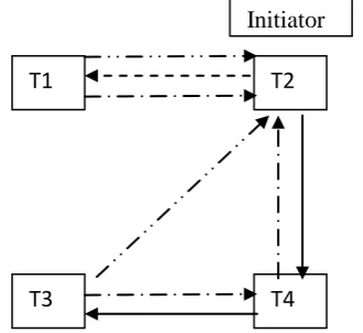
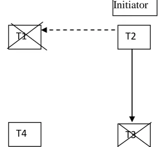
Fig 2 shows 1 site failure. In fig 2, initiator itself is predecessor. So it will compare its fault site ID with the fault site ID sent by T3. Both of them will have same fault site ID of T4. Fig 3 shows identification of 2 site failure. In this fault site ID identified by T1 will be T4 and the fault site ID identified by initiator will be T3. Since they are not same, 2 site failures are identified. 2 site failures are extension of theorem 2.
Theorem 3: In a deadlock cycle of size two, site failures can
be identified.
Proof: In [10], it is given that 2t+1 processors are needed to detect t failures using fault diagnosis model. However in our case, it can be inferred that t failures can be detected with minimum of one processor.
In our algorithm at most 2 site failures can be detected. Hence there are only two values for t, where t=1 or t=2. Since our algorithm is based on messaging, one processor itself is enough to deduce the faults in both the cases when t= 1 and t=2.
Fig 4 shows identification of two site failures by single processor itself. Since it will not receive acknowledgement message from its successor T3 and its predecessor T1, it will identify that both the sites have failed. But this will isolate this site from all the other sites and hence must be avoided. Fig 3 shows another case of 2 site failures, where more than one processor is needed to detect 2 site failures.
Theorem 4: The algorithm identifies whether the wait state is
due to live lock or deadlock in fault free environment.
Proof: In fault free environment, both forward as well as backward probe messages will reach initiator. If probe does not reach initiator in fault free environment, it is because of live lock. Some node in the wait for graph does not have any wait for edges. Then it cannot send forward or backward probes to its neighbors. So it will inform its status to initiator by sending return probe with WHITE color as mentioned in the algorithm for transactions.
7.
SCENARIOS
possible scenarios in a distributed system during deadlock detection phase.
Fig 1a: Deadlock in fault free environment
Scenario 1: Figure 1a depicts the scenario when deadlock
[image:5.595.76.249.88.267.2]occurs in fault free environment. Initiator T1 sends red colored forward and backward probes along dependency edge and opposite direction of dependency edge. When the initiator receives back both probes, it infers the presence of deadlock and that there is no site failure along the path. Then initiator (lowest priority) is victim. The color of the probe is RED.
Fig 1b: Live lock in fault free environment
Scenario 2: In Fig 1b, let us assume that T1-the initiator does
[image:5.595.333.529.225.398.2]not have predecessor. Then backward probe will not be sent back to the initiator. As T4 does not have any dependency edge, forward probe terminates at T4. T4 changes the forward probe to WHITE indicating live lock status and T4 is active. This is also a scenario in fault free environment.
Fig 1c: Live lock in fault free environment
Scenario 3: Fig 1c also depicts live lock status in fault free environment. Here T2 is assumed to be having least priority. Hence it becomes the initiator.T3 and T1 send forward and backward probes indicating live lock. So they change the color of the forward and backward probes WHITE and send return probe back to initiator.
Scenario 4: In fig 2a, let us assume T4 is faulty.T3 waits until
[image:5.595.90.245.352.495.2]time out for acknowledgement message from T4. If there is no acknowledgement message from T4, then it updates the fault vector for site 4, changes the color of probe message to ORANGE indicating site failure and sends return probe to initiator.T1 also sends backward probe. T4 sends no acknowledgement even after timeout. T1 concludes T4 faulty. It is confirmed by ORANGE forward probe from T3. Since
Fig 2a: Live lock/Deadlock in faulty environment (1 site failure)
the fault site ID in return probe from T3 matches with the faulty site deduced by initiator, it concludes one site failure and it may be a live lock or deadlock situation.
Fig 2b: Live lock / Deadlock in faulty environment (1 site failure)
.
Fig 2c: Live lock /Deadlock in faulty environment (2 site failure)
T1
T2
T4
T3
Initiator
Forward Probe Backward Probe Ack. Message Return probe
T1
T2
T4
T3
Initiator
T1
T2
T3
T4
Initiator
T1
T2
T3
T4
T1
T2
T3
T4
Initiator
Initiator
T1
T2
T3
T4
[image:5.595.315.534.436.747.2] [image:5.595.76.241.573.724.2]Scenario 5: In fig 2b, T2 is initiator. It sends forward probe to T3 and backward probe to T1. T4 is faulty. So T1 and T3 will not receive acknowledgement messages. They will change the probe color to ORANGE and send back to initiator after updating fault vector on T4. Since both T1 and T3 will have their fault site ID same, it is concluded that it is live lock/ deadlock due to single site failure.
Scenario 6: In fig 2c, Assume T3 and T4 are both faulty. T2
will send forward probe to T3. T3 will not send acknowledgement message. So T3 is updated as faulty on time out. T2 sends T1 backward probe. T1 forwards backward probe to T4. As T4 is also faulty, it will not send acknowledgement to T1. So T1changes return probe to ORANGE and updates T4 status. Since the fault side IDs updated by initiator and T1 are different, T2 will understand both T3 and T4 are both faulty and infer that it is two site failures scenario.
Fig 2d: Live lock/Deadlock in faulty environment (2 site failure)
Scenario 7: This is the worst case for 2 site failures with 4 sites in fig 2d. Let T1 and T3 are faulty. Initiator sends forward and back ward probes to them. On time out, since it does not receive acknowledgement messages from neither T1 nor T3, it deduces that T1 and T3 are both faulty. However the status of T4 is unknown, as it is unreachable by both T1 as well as T3. Since this algorithm can only detect at most 2 site failures, it cannot be inferred. However in [10], it is stated that at least 2t+1 processors are needed to detect t failures using PMC diagnosis model. However in our case it can be inferred that t failures can be detected with 2t – 1 processors itself.
8.
CONCLUSION
A new fault tolerant algorithm for Distributed Deadlock Detection and Resolution is proposed with the following improvements:
Initiator always knows the status of probe whether deadlock or live lock or site failure.
In [1] every non-faulty site tests other sites periodically for site failures. In the proposed algorithm the site failure is decided by acknowledgement messages. This improves the throughput of non-faulty sites.
Checking whether faulty sites are rectified is known by awake message. This situation is not handled separately in[1]
Only one site failure is handled in [1]. This paper however handles at most 2 site failure which improves fault tolerance
The color of the probe is used to indicate the status of the system. Red indicates deadlock with no site failure.
Orange indicates live lock or deadlock due to site failure. White indicates live lock due to a transaction having no dependency edge.
The worst case message complexity is 4n where n is the number of transactions. This occurs when there is no site failure and deadlock occurs. The four messages are the forward probe message and backward probe message to next nodes and acknowledgement messages for both forward and backward messages to senders (see fig 1a). Further fault identification is better than fault diagnosis
model, which needs 2t+1 processors to identify t failures. In the messaging mechanism, 2t-1 processors are enough to identify t failures.
9.
REFERENCES
[1] Pei-yu Li and Bruce McMillin, “Fault-tolerant Distributed Deadlock Detection/ Resolution”, IEEE Transactions on parallel and distributed systems, pp 224-230, 1993.
[2] M.Tamer Ozsu and Patrick Valduriez, “Principles of Distributed Database Systems”, Pearson Education, 1999.
[3] Chowdhary, A.N., Kohler, W. H., Stankovic, J.A. and Towsley, D., “A modified priority based probe algorithm for distributed deadlock detection and resolution”, IEEE Trans, Software Eng., vol. SE-15, pp.10-17, Jan. 1989.
[4] Mitchell, D.P. and Merrit, M.J., “A distributed algorithm for deadlock detection and resolution.” Proc. 3rd ACM Symp. Principles of Distributed Computing, Vancouver, Canada. pp. 282-284, Aug 1984.
[5] Roesler, M., Burkhard, W.A. and Cooper, K.B., “Efficient deadlock resolution for lock-based concurrency control schemes”, IEEE 8th Int’l conf. Distributed Computing Systems, pp. 224-233, 1988.
[6] Sinha, M.K and Natarajan, N., “A priority based distributed deadlock detection algorithm,” IEEE Trans. Software Eng., vol. SE-11, pp. 67-80, Jan. 1985.
[7] K.Mani Chandy and Jayadev Mishra, ”Distributed Deadlock Detection”, ACM Transactions on Computer Systems, Vol.1,No.2,Pages 144-156, 1983.
[8] R.C.Hansdah, Nilanjan Gantait, Sandeep Dey, “A Fault Tolerant distributed Deadlock Detection Algorithm”,Lecture Notes in Computer Science, Springerlink, Vol. 2571,pp 78-87,2002.
[9] J.Brzezinski, J.M. Helary, M.Raynal and M. Singhal, “Deadlock models and a General Algorithm for Distributed Deadlock Detection”, Journal of Parallel and Distributed Computing, vol. 31, pp112-125, 1995.
[10] Preparata et al., “On the connection assignment problem of diagnostic systems”, IEEE Transactions on Electronic Computers, Vol. EC-16, 1967.
[11] V.Geetha and n.Sreenath, “ Fault-informant distributed deadlock detection using colored probes”, Second International Conference on Advances in Communication, Network, and Computing, CNC 2011, Bangalore, India, March 10-11, 2011. Proceedings in LNCS-CICS.