Real Time Exact 3d Modeling of Objects from 2d Images
using Voxelisation
A.Sidhaarthan*
Electronics & Comm. Engg.,Coimbatore Institute of Technology, Coimbatore, TN, India.
B.Bhuvaneshwari
Electronics & Comm. Engg.,Coimbatore Institute of Technology, Coimbatore, TN, India.
N.Jayanth
Electronics & Comm. Engg., Coimbatore Institute of
Technology, Coimbatore, TN, India.
ABSTRACT
Reconstruction of 3D object models using voxelisation can be a better way for exact reconstruction of 3D models in a real time environment. First the 2D images are acquired from cameras and they are processed to find the region of interest. From the region of interest the 2D images are reconstructed to 3D models. The proposed algorithm requires minimum requirement of resources when compared to other 3D reconstruction methods like NURBS or SIFT etc. The algorithm is built in a simple way that it can be implemented in any moderate embedded systems. The algorithm is tested in various platforms under limited resources for its performance and is found to be effective. The measurement of the object parameters is comparatively very easy in this method when compared other methods. The constructed 3D models can be displayed in stereographic displays or given to a 3D printer for reproduction or can be used as an input for further processing.
General Terms
Image Registration, 3D Image modeling
Keywords
3D reconstruction, real time modeling, 3D modeling, 2D to 3D mapping
1.
INTRODUCTION
This paper discusses an algorithm that can be used for exact 3D reconstruction from 2D images in a real time environment. The 3D reconstructions of the objects are gaining popularity due to the development of modern day 3D printers and the growing requirement of the 3rd dimension for quality control, monitoring and manufacturing. There are various algorithms like SIFT [1], NURBS [2] proposed for reconstruction of the object from 2D images. But they are computationally expensive, time consuming and also require vast resources [3, 4]. The algorithm proposed even works under limited resources and takes quite less time when compared to the other algorithms in practice. The algorithm is implemented in various resource limited environments and the results are compared.
The proposed method uses the idea of direct voxelisation of the 2D images and mapping them to 3D. This method is based on the simple fact that if 2D images can be represented as the collection of tiny squares called pixels then the 3D models can be expressed as the collection of tiny cubes and we call them as voxel i.e. Volume Pixel [5]. This gives us the comfort to
directly measure the object parameters directly from the object without any difficulties by using the number of voxels as the measure.
2.
RELATED WORK
There are various reconstruction techniques already proposed for reconstruction of 3D objects from 2D images. Representing a 3D object using NURBS is one famous method. But the main disadvantage in this technique is that the accuracy of the image is lost [2]. This also requires hardware rendering to make the process real time [6] and hence it is slow when used in moderate powered PCs which run with limited resources. The NURBS model also has the disadvantage of high computational complexity and it is time consuming. So applying these kinds of models in real time is difficult and requires more resources and cost. It also takes a quite high amount of calculations to find the field points or points of interest for a curve and to map it to the region of interest [3]. At most little complex cases, the plotting of the basic curve is not accurate and it requires manual setting of the curves and the interest points.
Another algorithm used in 3D reconstruction is SIFT which is a feature detection algorithm. SIFT is nowadays widely used for object detection. But with the help of SIFT it is also possible to reconstruct 3D object. It also requires a sequence of images from the source to reconstruct a 3D model [4]. This involves finding key points by using Gaussian matrix and taking Difference of Gaussian (DoG). From the results got from DoG matrix extrema are detected and then the keypoints are found [8]. This gives matches between two images, which can be used to merge the images using the keypoints (See Figure 1). Using sequence of images and from the matches between every subsequent image, the images are reconstructed to 3D [4, 7]. Hence, this method is also proved to be computationally expensive and also resource expensive if it is used for real time applications [1].
There are several other methods proposed depending on the former proposed techniques combined with other like using epipolar geometry, RANSAC, etc., [9]. But they are not suited for real time applications as they are computationally expensive. Also that the image reconstructed by following them is not accurate in dimensions.
3.
PROPOSED METHOD
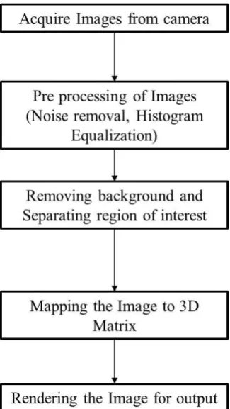
The proposed method uses the idea of voxelisation of 2D images to construction a 3D image model. This technique is fast, requires less resources and accurate. The process flow can be described in the following flow chart (see Figure 2).
Fig.2. Process flow
3.1
Acquiring Images from camera
The images of the object can be obtained in two ways: (i) by using multiple cameras at fixed angles or (ii) by using single camera and varying the angles [10]. Here for cost
[image:2.595.315.449.191.368.2]management images are obtained by using a single camera by varying the angles of the camera as illustrated (See Figure 3). The number of images needed to model the object depends on the complexity of the shape of the object. If the object is simple then two images are enough for modeling. If the complexity of the object increases for prefect reconstruction more number of images is needed. If an image is very complex an image sequence can be used for a better modeling.
Fig.3. Acquiring Images at various angles using camera
3.2
Pre-processing of Images
Images acquired from camera contain various noises. The most general noise that occurs in images is salt and pepper noise and Gaussian noise. Due to various other factors other type of noise like random noise etc., also occurs in image. There are various ways available to remove noises from the image. Since we used industrial standard CCD cameras which are low noise cameras and the noise we get is mostly Gaussian noise [11, 12] and it is simply removed by using a Low Pass Filter or by wavelet filtering based on the application. If there is presence of salt and pepper noise a median filter can be used for noise removal [13,14].
3.3.
Removal of background and Separating
ROI
[image:2.595.54.217.382.671.2]Then the gray scale image is thresholded with a proper threshold value and the pure black and white image is obtained. The ROI is cropped from the image eliminating the background.
3.4. Mapping image to 3D
In the proposed algorithm for modeling a 3D object the technique used is direct voxelisation. The processed images i.e., the pure black and white images are obtained. Considering a simple object only two images are sufficient. From the images the dimensions of the object can be measured in pixels. The object is considered to fit in a polygon based on number of images. If the images are two then the model is fit inside a cuboid or a cube. The images are placed in the angles they are acquired i.e., on the sides of the polygon and the pixels in the images are extruded backwards. The algorithm is explained below.
Let image1 and image2 be the images. Let imageN (width,height) denotes the pixel in the specific location. Let matrix3d be the matrix of the 3D image mapped. pixel(imageN(width,height)) represents the presence of the pixel in the position. N is the image number. The algorithm is explained as pseudo codes below.
count1 i=1 to width of image1
count2 j=1 to height of image1
count3 k=1 to width of image2
if pixel(image1(i,k)) = pixel(image2(k,i))
matrix3D(j,k)=pixel(image1(i,k))
else
matrix3D(j,k)=pixel(empty)
end if
end count1
end count2
end count3
This creates a 3D matrix with the matrix size of height in the x axis, width in the y axis and depth in the z axis everything measured in teams of pixels. The iteration increases with increase in the number of images.
Now, after forming the matrix for 3D reconstruction we enter the phase of measuring the object that was modeled. Let FOVx, FOVy and FOVz be the field-of-view and Nx, Ny and Nz be the CCD array size of the camera used respectively for X, Y and Z axis. Let x, y and z be the size of the model in the respective axis X, Y and Z.
x = FOVx/Nx
y = FOVy/Ny
z = FOVz/Nz
3.5. Rendering the Image
The 3D matrix formed is in the form of slices. The next step is rendering the slices as voxels. The matrix is checked for the depth of the slices. The outer cover of the matrix is found using the slice depth and while rendering the matrix in 3D form, horizontal planes are introduced which has their rendering limits within the model area, which is the slice depth. If the render limits exceed the model area, the plane is cut at the place and resumed again where the model slice value becomes true. The process is less time consuming as only slices are added and checked for the presence in the model while rendering the image.
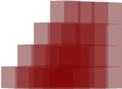
[image:3.595.319.533.265.421.2]An example of formation of voxels for an image is shown (See Figure 4). The image shows the voxels formed in transparent manner so that the formation of voxels from the slices can be easily understood.
Fig.4. Image displaying the formation of Voxels from slices
4. RESULTS AND DISCUSSIONS
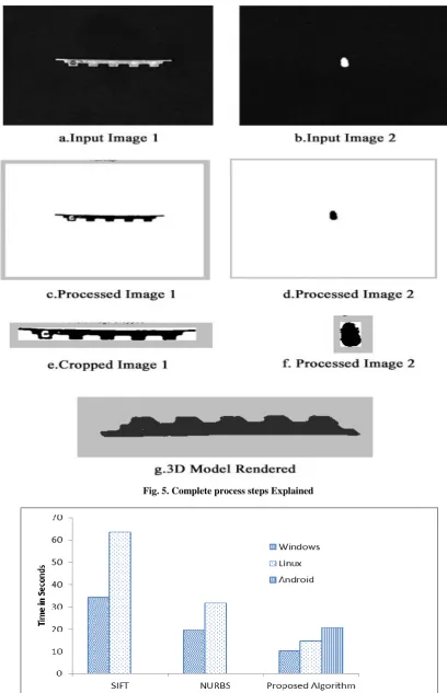
The example result for a model is shown (See Figure 5). The input to the algorithm is two images (minimum) taken at the two sides of the object. The lighting used here for the object is from the front (See Figure 5.a and Figure 5.b). The acquired images are preprocessed i.e., the noise in the images are removed by using Median Filter. Then thresholding is applied to the filtered image (See Figure 5.c and Figure 5.d). Now the Region of Interest is cropped from the thresholded image. The cropped image contains only the ROI without the background (See Figure 5.e and Figure 5.f). From the ROI the 3D model is reconstructed (See Figure 5.g).
This explains the output at every stage and the final 3D reconstructed model is shown. The previous methods in practice are all mainly probability based algorithms. But the proposed method is based on geometry of the object. Hence the measurements of the model acquired from the proposed algorithm are 95% accurate. The proposed method is found highly efficient and less time consuming when compared to the other existing methods. The existing methods like NURBS and SIFT takes a minimum of twice the time taken by the proposed algorithm.
Fig. 5. Complete process steps Explained
to the other methods i.e. SIFT and NURBS. The resources and the environment details are shown in the table (See Table 1).
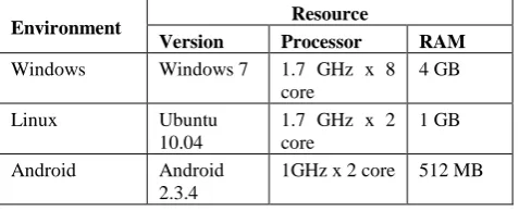
Table.1: Resources in various environments
Environment Resource
Version Processor RAM
Windows Windows 7 1.7 GHz x 8 core
4 GB
Linux Ubuntu
10.04
1.7 GHz x 2 core
1 GB
Android Android 2.3.4
1GHz x 2 core 512 MB
When the algorithms are tested in Android the algorithm for modeling based on NURBS and SIFT threw a stack overflow error. But the proposed algorithm executed without errors in an environment with very limited resources.
From the results as discussed (See Figure 6), we can conclude that the proposed algorithm works efficiently in all cases in different platforms even in the environment where the resources were limited. The algorithm can be implemented even in handheld devices as the algorithm runs efficiently without any memory overflow error whereas when SIFT and NURBS when used for reconstruction in Android memory overflow error was thrown.
The main advantages of using the proposed algorithm is that the 3D model is constructed is exact in dimensions, requires less resources and less time. The model constructed is made out of voxels and hence it doesn’t show smooth edges. This can be overcome by using high resolution cameras which increases the number of voxels in the model and hence by smoothening the model.
5. ACKNOWLEDGEMENTS
The authors would like to thank Dr.A.Rajeswari, Prof. T. Senthil Vinayakam and Mr. T. Balakumaran of Coimbatore Institute of Technology, Coimbatore and Mr.D.Srinivasan, Vizzitec Solutions Pvt. Limited, Coimbatore for proving with the resources.
6.REFERENCES
[1] Dang Trung Kien, 2005, A Review of 3D Reconstruction from Video Sequences, ISIS technical report series, University of Amsterdam The Netherlands.
[2] G. Moustakides, D. Briassoulis, E. Psarakis, E. Dimas, 2000, 3D image acquisition and NURBS based geometry modeling of natural objects, Advances in Engineering Software, Elsevier.
[3] Anton van den Hengel et al, 2007, VideoTrace: Rapid interactive scene modeling from video, ACM Transactions on Graphics, Vol. 26, No. 3, Article 86.
[4] Shaoxing Hu et al., 2008, 3D Reconstruction from Image Sequence Taken with a Handheld Camera, The International Archives of the Photogrammetry, Remote Sensing and Spatial Information Sciences. Vol. XXXVII. Part B4. Beijing.
[5] http://bestthing.flyingpudding.com/2007/04/30/define-voxel/
[6] Mohamad Ivan Fanany.D, 2008, Shape Modelling from Erroneous and Few Shaded 2D Images, MS Thesis, Tokyo Institute of Technology, Japan.
[7] Thanh Duc Dao, 2008, Underwater 3D reconstruction from stereo images, MS Thesis, University of Girona, Spain.
[8] Lowe, D.G, 2004, Distinctive Image Features from Scale-Invariant Keypoints, International Journal of Computer Vision.
[9] Richard Hartley and Andrew Zisserman, 2003, Multiple View Geometry in Computer Vision, Cambridge University Press.
[10] Lana Madracevic, 2010, 3D Modeling From 2D Images, MIPRO 2010, Opatija, Croatia.
[11] http://learn.hamamatsu.com/articles/ccdsnr.html
[12] http://www.theimagingsource.com/en_US/topics/camera
[13] Min Li et al, 2009, The measurement system of hardware’s shape and dimension based on image processing method, Proceedings of eighth international conference on Machine Learning and Cybernetics, Baoding.
[14] CAO Zhi-hua, SONG Bin-heng, 2006, A Fast algorithm for Median Filtering in Multiform Window, Application Research of Computers, 3(3):59-6.