© 2018, IRJET | Impact Factor value: 6.171 | ISO 9001:2008 Certified Journal | Page 3400
High Throughput Polar Code Encoder Using Pipelined Architecture
and It’s FPGA Implementation
Rohan B. Pachange
1, A. M.
Shah
21
Electronics and Telecommunication Department, GCOE, Amravati [MH], India
2
Assistant Professor, Electronics and Telecommunication Department, GCOE, Amravati [MH], India
---***---Abstract -
In recent years it became prime important toutilize the channel capacity at full scale. Polar codes have come into limelight due to its provable channel achieving capacity especially in symmetric binary memoryless channels. Also, it has been observed that polar codes are the most favorable error correcting codes. Channel polarization is the key principle behind the construction of polar code. Basically in the polar code transmission channel is segregated into complete noisy and noiseless channel. In this paper, we propose a high throughput polar code encoder and analyze the encoding process on FPGA platform using very-large-scale integration implementation. We provide the implementation result of pipelined architecture for polar code encoder specifically for 8- bit input.
Key Words: Channel Capacity, polar code, error correcting codes, channel polarization, FPGA.
1. INTRODUCTION
Polar codes were proposed in 2009 by Erdal Arikan, which exhibited the provable capacity-achieving code. From the statement of Shannon's theorem for noisy channel coding, it’s become an elusive goal to construct the provably capacity-achieving code with low encoding and decoding complexity. Polar codes due to their provable capacity achieving property have vast applications. Hence to make these applications economical in time and power constraints, several proposals have been put forth for maximizing throughput and minimizing hardware complexity along with focusing on the reducing the transmission delay and the number of LE's for Altera Cyclone II device.
In this work, we describe a new architecture for the implementation of polar code encoder using the pipelined architecture on the reconfigurable platform i.e. Cyclone II device.
The proposed pipelined architecture is designed to achieve the objective of reduction in delay element by using the pipelined at input, output and intermediate stage.
For a particular system, we measure the performance of the system with respect to two key terms i.e. latency and the maximum clock frequency, whereas the latency of the system can be defined as the total time required to move a particular signal from the input of a system to its output and the maximum clock frequency. In any digital circuitry, the
latency occurs at the minimum level when the data path for the signal entirely comprised of the logic stages, in such circuits the total time required for the signal propagation and the system clock period both are treated as the latency. Hence to achieve the objective of the proposed topic i.e. reduction in delay, we inserted the registers into the data path.
1.1 Polar Codes
Preliminaries
Definition 1
(Binary input discrete memoryless channel)
A memoryless channel W with input alphabet X, output alphabet Y, and transition probabilities W(y/x), x ϵ X, y ϵ Y is denoted as W: X → Y. the input alphabet X ϵ {0,1}, whereas output alphabet and transition probabilities can have any arbitrary valid values. Such a channel is referred to as a binary input discrete memoryless channel.
Definition 2
(Symmetric B-DMC)
A B-DMC, W, is said to be symmetric channel if there exists a permutation π such that
π-1 = π
W(y/1) = W(π(y)|0)
Definition 3
(Memoryless channel)
© 2018, IRJET | Impact Factor value: 6.171 | ISO 9001:2008 Certified Journal | Page 3401 1.2 Channel Polarization
Channel polarization is an operation by which one manufactures out of N independent copies of a given B-DMC W a second set of N channels that show a polarization effect in the sense that, as N becomes large, the symmetric capacity terms tend towards 0 or 1 for all But a vanishing fraction of indices i. This operation consists of a channel combining phase and a channel splitting phase.
Polar Coding
Polar-coding is a capacity-achieving code setting up method mainly for binary-input discrete memory less channels. This can be done by the phenomenon of channel-polarization that every channel processes a flawlessly secure else a fully noisy channel as the code-length drives beyond over a collective channel built using a suite of N same sub channels. 50% of power consumption can be reduced by parallel processing of two-input samples which reduces the frequency of operation by. For small or adequate polar code, fault performance by the Cyclic Redundancy Check (CRC) supported Successive Cancelation List (SCL) decoding procedure is improved than the Successive Cancelation (SC) decoding process, which isn't appropriate for lengthy polar-codes owing to extreme hardware density. Linear block code with appropriate parameters can be used to perform block wise decoding of outer codes if there is not take into account, not necessary polar, as Ci. Path-search techniques for coding tree polar-codes are given as combined depiction of the SC, SCL, and SCS decoding algorithm. Integration of SCL and SCS, a new decoding process called the Successive Cancellation Hybrid (SCH). A semi-parallel encoder based partial-sum update features as accessible architecture for SC decoding of polar-codes. This module uses Static Random Access Memory (SRAM) for storing and uses a fixed data path.
This design influences a multi-level quantization structure for Limb Lengthening and Reconstruction society (LLRs), reducing the memory usage and area. In addition, Arikan furnished a specific construction system for polar different understanding theoretic problems in an effective method then again, polar-codes require tremendous code lengths to strategy the capacity of the underlying channel. Coding theorem by Shannon’s proof for noisy channel is random coding method which is used to exhibit the presence of ability-reaching code structures without revealing any designated one. In realistic implementations, the memory measurement and the usage of XOR-gates expand because of code size increases. The polar-decoders is 8 times more than the successive cancellation decoder to increase the throughput of polar decoding by an order of magnitude. None of the previous works has deeply analyzed the best way to the polar-code encoding effectively, although quite a lot of trade-offs are feasible among the latency and hardware difficulty. This design synthesized in a CMOS technology of 130nm for a parallel structure. Then again, the complex parallel structure has benefits of low latency and high throughput. The Polar Cosine Transform (PCT) algorithm
used to divide the image into overlapping patches and then feature vectors are extracted from the patches. Hence, the polarization method is used in the image encryption and decryption. Folding Transformation is a technique in which the number of butterflies in the same column is mapped into one buttery unit. A pipelined parallel Fast Fourier Transform (FFT) architecture which has a lesser power consumption compared to serial FFT architectures. Digital Signal Processor (DSP) operations are repetitive and periodic in nature. The lifetime chart specifies the Life period of all variables in a single frame and the subsequent frames are computed in a periodic manner.
2. POLAR ENCODING
Since polar error correcting code (ECC) belongs to the category of linear block codes, the whole process can be represented by generator matrix. For a code length N or 2n, the generator matrix is 0 achieved by applying nth power to
the kernel matrix ‘F’. An information block consisting of both input and frozen bits is mapped to The code word block ON where GN is the generating matrix. Once the generator matrix is obtained, code word vector is calculated by O = I * GN, where I and O represent input information and output code word vectors respectively. Polar codes employ a transformation process called channel polarization. Polar coding is, in fact, polarizing a set of B-DMC, W, by iterative application of Single step polar transform. The resulting sub channels are polarized so we need to select good channels to communicate with them at rate = 1 and freeze bad channels to zero. Moreover, frozen channels are known both to encoder and decoder.
3. SYSTEM DEVELOPMENT
In the proposed model we have implemented the polar code encoder architecture and for the fast data transmission and reducing the total power constraints we have implemented the pipelined architecture. In pipelined architecture, we have used three-stage pipelined. The three stages of pipelining are implemented at the input level, after the transform inputs, and at the output stage. As we have implemented the 8-bit architecture in which we have used the frozen bits typically at four positions so our first register will be of four input and later two stages are that of 8-bit inputs which are placed at after the transform inputs block and another in between main encoder and the output stage.
Fig.-1 System RTL View
© 2018, IRJET | Impact Factor value: 6.171 | ISO 9001:2008 Certified Journal | Page 3402 means the multiplication of generated keyword with the
kronocker matrix of the same order.
3.1 Frozen Bits
This unit decides whether the index of the code word bit comes under an information set or frozen set, if the bit is a frozen bit then the output bit is set to 0 or if the bit is an information bit then further process is done to obtain estimate bit which can be either 0 or 1. The appropriate index corresponding to each set is chosen by generating the control signal.
3.2 System Stages
Input Stage
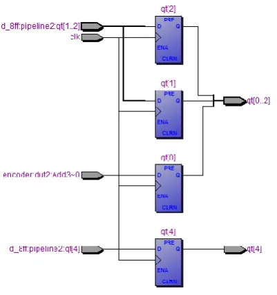
[image:3.595.343.512.88.265.2]As per our proposed model, to achieve the stated objectives of power efficiency and the latency we have implemented three-stage pipelined architecture in which very first stage is the input stage.
Fig.-2 Input Stage
Here in input stage, we are having the eight-bit data and also we have used the frozen bits so as to segregate between the useful and useless data as 1 and 0 respectively. Also, the polar code generation follows the FFT buttery algorithm so the code word transmission is carried out in sequence q(2)-q(0)-q(3)-q(1). Which is clearly indicated in the above stage schematic diagram.
Intermediate Stage
[image:3.595.76.254.336.528.2]Here in designed model, the intermediate stage of the pipelined architecture is nothing but the stage after transforming the inputs which are fetched from the input stage and are ready to be encoded. In practice at input stage, we are having an input of 4-bits as remaining four bits are the frozen ones. Next, to it these input bits transformed into the code word of length 8-bit. These are feed to the intermediate stage having 8-bit input and 8-bit output.
Fig.-3 Intermediate Stage
When we are implementing the system model using pipelined architecture it next provided to the entity termed encoder which we have designed to perform the polar code encoding action. The pipelined architecture is synchronous with a clock which will contribute to reducing the propagation delay by reducing the slack content which we will see in performance analysis section. The F (max) for the designed system is 930.23 MHz but the restricted F (max) is 420.17 MHz. This reported F (max) is for every clock in the design, regardless of the user specified clock periods. F (max) is only computed for paths where the source and destination registers or ports are driven
by
the same clock. Paths of different clocks, including generated clocks, are ignored. For paths between a clock and its inversion, F (max) is computed as if the rising and falling edges are scaled along with F(max), such that the duty cycle(in terms of a percentage) is maintained. Altera recommends that you always use clock constraints and other slack reports for sign-off analysis.Output Stage
© 2018, IRJET | Impact Factor value: 6.171 | ISO 9001:2008 Certified Journal | Page 3403 Fig.-4 Output Stage
4. ANALYSIS
[image:4.595.305.565.106.232.2]4.1 Resource Utilization
Table -1: Routing Resources Utilization
Routing Resources Utilization
Block Interconnects 8/94,460(≤1%)
C16 Interconnects 1/3,315(≤1%) C4 Interconnects 16/6,084(≤1%)
Global Clocks 1/16(6%)
Local Interconnects 8/33,216(≤1%)
R24 Interconnects 1/3,091(≤1%)
R4 Interconnects 33/81,294(≤1%)
4.2 Propagation Delay
[image:4.595.303.567.270.351.2]Propagation Delay is the amount of time it takes for a signal to travel from a source to a destination. Propagation Delay is a fundamental concept of how digital circuits work. Propagation delay is fundamentally important to sequential logic. Again, sequential logic is logic that is driven by a clock. The amount of time it takes for the output of the first logic element to travel to the input of the second logic element is the Propagation Delay. The further apart those two logic elements are or the more combinational logic in the middle, the longer the propagation delay between the two of them. The longer the propagation delay, the slower your clock is able to run. The purpose of any timing analyzer in your FPGA or ASIC tools are to tell you if you have problems meeting timing. If your design is too slow to run at the clock frequency you want, you will get timing errors and your design will likely not work correctly.
Table -2: Delay chain for without pipeline architecture
Input Port Output Port Delay
Data_in[0] Encodedata_out[0] 6.712
Data_in[1] Encodedata_out[0] 6.689
Data_in[1] Encodedata_out[1] 5.668
Data_in[2] Encodedata_out[0] 5.963
Data_in[2] Encodedata_out[2] 5.142
[image:4.595.45.277.407.537.2]Data_in[3] Encodedata_out[0] 6.318 Data_in[3] Encodedata_out[4] 5.648
Table -3: Delay chain for withpipeline architecture
Name Pad to core 0 Pad to core 1
Data_in[0] 171ps 171ps
Data_in[1] 171ps 171ps
Data_in[2] 171ps 171ps
Data_in[3] 170ps 170ps
4.3 Slack Analysis
Power dissipation remains one of the critical challenges in microprocessor design. It requires innovation at all design levels to sustain performance scaling. Minimization of the total device width, without accounting for these circuit properties that determine the power consumption, does not guarantee that the optimized (tuned) circuit will operate under minimum power consumption. The slack threshold parameter for the area minimization and FAR tuning modes has two very different meanings. In the area minimization tuning mode, the slack threshold is a constraint and has to be satisfied or the optimization problem is infeasible and the tuned circuit is suboptimal.
Fig.-5 Slack Histogram
5. CONCLUSION
[image:4.595.308.572.535.669.2]© 2018, IRJET | Impact Factor value: 6.171 | ISO 9001:2008 Certified Journal | Page 3404 architecture. From the comparative analysis, it is observed
that propagation delay is reduced in the architecture with the pipeline as compared to architecture without the pipeline. From pipeline architecture, the slack histogram also obtained and studied the behavior of signal at various instants. Also, it's been seen from the observations that breaking down a particular system into stages turns out to be beneficial in terms of the time constraint as it reduces the propagation delay of the system. This proposed approach supports any degree of parallel processing, solving all four problems, (higher throughput, lower latency, improved error correction capability, and flexibility). It maintains compatibility with any turbo encoder, ensuring synergy with older standards and future proofing of those to come.
REFERENCES
[1] Alok Arpure, Somulu Gugulothu, “FPGA Implementation of Polar Code Based Encoder Architecture”, International Conference on Communication and Signal Processing, April 6-8, 2016, India.
[2] Erdal Arkan, Senior Member, IEEE, “Channel Polarization: A Method for Constructing Capacity-Achieving Codes for Symmetric Binary-Input Memoryless Channels”, IEEE TRANSACTIONS ON INFORMATION THEORY, VOL. 55, NO. 7, JULY 2009. R. Nicole, “Title of paper with only first word capitalized,” J. Name Stand. Abbrev., in press.
[3] Ramtin Pedarsani, S. Hamed Hassani, School of Computer and Communication Systems, EPFL Lausanne, Switzerland., “On the Construction of Polar Codes”, 2011 IEEE International Symposium on Information Theory Proceedings.
[4] Alptekin Pamuk, Department of Electrical-Electronics Engineering Bilkent University Ankara, TR-06800, Turkey [email protected], “An FPGA Implementation Architecture for Decoding of Polar Codes”, 2011 8TH International Symposium On Wireless Communication Systems, Aachen.
[5] Manohar Ayinala, Student Member, IEEE, Michael Brown, and Keshab K. Parhi, Fellow, IEEE, “Pipelined Parallel FFT Architectures via Folding Transformation”, IEEE Transactions On Very Large Scale Integration (VLSI) Systems, Vol. 20, No. 6, June 2012.
[6] Kai Chen, Student Member, IEEE, Kai Niu, Member, IEEE, and Jiaru Lin, Member, IEEE , “Improved Successive Cancellation Decoding of Polar Codes”, IEEE Transactions On Communications, Vol. 61, No. 8, August 2013.
[7] Gabi Sarkis, Pascal Giard, Student Member, IEEE, Fast Polar Decoders: Algorithm and Implementation, IEEE Journal On Selected Areas In communications, Vol. 32,No. 5, May 2014.
[8] Chuan Zhang and Keshab K. Parhi, Fellow, IEEE, Latency Analysis and Architecture Design of Simplified SC Polar Decoders, IEEE Transactions On Circuits And Systems: Express Briefs, Vol. 61, No. 2, February 2014.
[9] Hoyoung Yoo, Student Member, IEEE, and In-Cheol Park, Senior Member, IEEE, “Partially Parallel Encoder Architecture for Long Polar Codes”, IEEE Transactions On Circuits And Systems: Express Briefs, Vol. 62, No. 3, March 2015.
[10] Mamatha Sarah. Oommen S. Ravishankar, FPGA Implementation of an Advanced Encoding and Decoding Architecture of Polar Codes, 2015 International Conference on VLSI Systems Architecture, Technology and Applications (VLSI-SATA).
[11] Huayi Zhou, Xiao Liang, Chuan Zhang, Shunqing Zhang, and Xiaohu You National Mobile Communications Research Laboratory, Southeast University, Nanjing, China Intel Collaborative Research Institutes on Mobile Networking and Computing, Intel Labs, Shanghai, China, Successive Cancellation Heap Polar Decoding,2016 IEEE Global Communications Conference (GLOBECOM)
BIOGRAPHY:
Rohan B. Pachange was born in 1995. He received the B.E.
(Electronics and
Telecommunication) degree from the Government College of Engineering, Aurangabad (MH), in 2016. His research interests include VLSI and Wireless communication. He is currently pursuing M.Tech
(Electronic System and