The Binary Tree Roll Operation: Definition, Explanation
and Algorithm
Adrijan Božinovski
School of Computer Science and Information Technology
University American College Skopje Treta Makedonska Brigada 60
1000 Skopje, Macedonia
Nevena Ackovska
Faculty of Computer Science and Engineering University “St. Cyril and Methodius”
Rugjer Boškoviḱ 16 1000 Skopje, Macedonia
ABSTRACT
The paper introduces an operation on a binary tree, called binary tree roll, or roll of a binary tree. Two versions of the binary tree roll, counterclockwise and clockwise, are presented. The operations are mathematically defined and graphically presented. It is explained how the binary tree roll actually coincides with the process of turning the entire tree 90 degrees counterclockwise or clockwise. To visually explain and perform the roll operation, the concepts of a wedge node, true ancestor, illusory ancestor, illusory root and illusory ancestral stem of nodes are introduced, as well as the visual operations of turning and downshift. Both roll operations are implemented using programming algorithms. The algorithms are explained, and all the situations that might be encountered during processing the roll operation are examined and resolved. Thus, the paper gives a mathematical introduction of both binary tree roll operations, gives their visual explanations and offers algorithms for their implementations using a computer.
General Terms
Algorithm, binary tree
Keywords
binary tree, roll, operation, turning, downshift, algorithm
1.
INTRODUCTION
Trees are fundamental concepts in computer science, and are frequently used to keep track of ancestors or descendants, sports tournaments, organizational charts of large corporations and so on [1]. Trees arise naturally as means to describe state spaces during the course of recursive algorithm processing, such as backtracking [2, 3], and also games (like tic-tac-toe, chess etc). Trees are composed of nodes and edges, the latter serving as links between nodes. The term “tree” implicitly carries an assumption that the tree is rooted, meaning that a special node is designated as the root of the tree, and all nodes that are connected to it are its sub-nodes (also called children or descendants) – the root is assigned the highest order in the
nodes having the same parent node. Binary trees are special kinds of trees, where each node (including the root) has at most two sub-nodes. Thus, in a binary ordered tree, the notions of a left and right sub-node are commonly used. Tree traversal means processing every node by performing a certain function on it exactly once (a basic function would be to print out the node‟s information, for example). Since trees can be viewed as acyclic undirected graphs [4], the basic graph traversal techniques, namely depth-first and breadth-first traversals, are also applicable to trees. Adding the additional constraints of a root and at most two sub-nodes to every node, so as to obtain a binary tree, yields three depth-first traversal techniques, which are preorder, inorder and postorder, and one breadth-first traversal technique, which is level-order traversal [1].
The notions of “function” and “operation” on a binary tree are commonly used as synonyms (e.g. [5, 6, 7]). However, in this paper, a distinction will be made. A function on a binary tree is a procedure that does not change the internal structure of the binary tree. Thus, all traversals of the tree would be functions, as well as finding the height of the tree, the width of the tree, the number of nodes in the tree etc. On the other hand, an operation on a binary tree is a procedure that changes the internal structure of the binary tree. In other words, insertion of a node in the tree, deletion of a node in the tree, tree rotation [8] etc would all be operations on a binary tree. Because the structure of the binary tree changes when an operation is performed on it, promotion and demotion of nodes necessarily takes place, in a sense that nodes get positioned higher or lower in the hierarchy (i.e. at a shorter or longer distance from the root, respectively) as a result of the operation.
assumed that all the elements of every binary tree in question will be different from one another.
The counterclockwise roll of a binary tree, abbreviated CCW() henceforth, can now be defined. Given binary trees T1
and T2, as well as the preorder(), inorder() and postorder()
functions, which yield the respective traversals, operation CCW() is defined as
(1)
In other words, upon CCW(), the preorder traversal of the original tree is identical to the inorder traversal of the tree obtained by the counterclockwise roll, and the inorder traversal of the original tree is identical to the postorder traversal of the tree obtained by the counterclockwise roll.
Likewise, the clockwise roll of a binary tree, abbreviated CW() henceforth, can be defined as
(2)
Similarly, upon CW(), the inorder traversal of the original tree is identical to the preorder traversal of the tree obtained by the clockwise roll, and the postorder traversal of the original tree is identical to the inorder traversal of the tree obtained by the clockwise roll.
3.
EXAMPLES
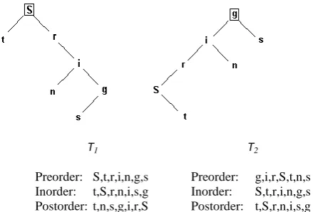
[image:2.595.317.537.134.283.2]Figure 1 shows an example of these processes and their results. The preorder and inorder traversals of T1 are equal to the respective inorder and postorder traversals of T2. In other words, using the preorder traversal of T1 as the inorder traversal of some new tree and the inorder traversal of T1 as the postorder traversal of the new tree, and thus unambiguously reconstructing the new tree, will yield tree T2 as a result. Conversely, taking the inorder traversal of T2 and using it as the preorder traversal of a new tree and the postorder traversal of T2 and using it as the inorder traversal of the new tree, unambiguously reconstructing such a tree will
Figure 1:Example of a binary tree roll. CCW(T1) = T2. CW(T2) = T1. The root of every tree is marked with a
rectangle.
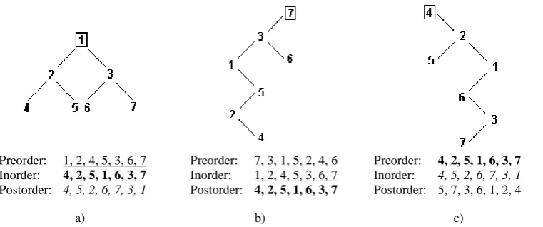
Figure 2 shows another example. More specifically, Figure 2a shows a balanced tree, Figure 2b shows the result obtained by counterclockwise roll of the tree in Figure 2a and Figure 2c shows the result obtained by clockwise roll of the tree in Figure 2a.
Viewing trees T1 and T2 in Figure 1 leads to the thought that the two trees are turned 90 degrees respective to one another. Repeated testing has shown that this is indeed the case, and this has led to the roll operation originally being called “rotation of a binary tree” [17]. However, this is not always the case, as presented in Figure 2. The trees in Figure 2b and Figure 2c are clearly not obtained by simply rotating the tree in Figure 2a for 90 degrees counterclockwise and clockwise, respectively, even though, when viewing their respective traversals, it can be seen that they conform to definitions (1) and (2) for counterclockwise and clockwise roll, respectively. In the next section it will be explained why the term “binary tree roll” (or “roll of a binary tree”) is more appropriate for the given operation and how the “rotation of a binary tree” can be thought of as a special case of the roll of a binary tree. Moreover, the term “roll” will be used to denote the operation itself, rather than the result of it (as previously implied in [17]). Also, in all figures, the root of every displayed tree will be marked with a rectangle, for clarity.
T1
Preorder: S,t,r,i,n,g,s Inorder: t,S,r,n,i,s,g Postorder: t,n,s,g,i,r,S
T2
4.
VISUAL EXPLANATION
In order to link the roll operation with the notion of a tree being turned for 90 degrees in some direction, the turning of a binary tree is defined as a visual operation, in which the tree is turned 90 degrees in some direction, so that the rightmost or leftmost node in the original tree becomes the root of the new tree, i.e. is placed the highest in the hierarchy. In the first case, a counterclockwise turn takes place, and the second case a clockwise turn takes place. Since this operation is purely visual, it can be stated that only the links get modified so that the new tree is obtained, whereas the node elements remain in their original, i.e. “unturned”, positions.
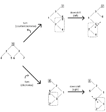
Consider the balanced tree in Figure 3a (it is identical to the tree in Figure 2a but is repeated here for clarity). Visually, every ancestor node in the tree should be displayed higher than its descendant nodes, but, upon turning (Figure 3b and Figure 3c), some ancestor nodes are displayed lower than their descendant nodes. Specifically, in Figure 3b node „2‟ has one of its descendants (node „5‟) displayed higher in the picture, and in Figure 3c the same applies to node „3‟ (one of its descendants, node „6‟, is displayed higher in the picture). If the level of hierarchy is defined as the number of edges that a node is farther from the root, then it is clear that some internal (i.e. non-root) nodes are represented visually higher than their
ancestor nodes. Such nodes form an illusory ancestral stem of nodes, containing nodes that are displayed higher than a certain node, but are essentially lower in the hierarchy (i.e. further from the root of the tree) than it. A node that has an illusory ancestral stem of nodes is called a wedge node, and it contains both a true ancestor (which is closer to the root of the tree) and an illusory ancestor, which is the first node connected to the wedge node along the illusory ancestral stem.
It is possible that the illusory ancestor be the only node of the illusory ancestral stem (as depicted in Figure 3), but it‟s also possible that the illusory ancestral stem contain more than one node. In that case, the illusory root is important, which represents the node that is as displayed visually the highest along the illusory ancestral stem of nodes. If the illusory ancestral stem contains only one node, i.e. only the illusory ancestor, then it is identical to the illusory root.
To maintain the visual representation that ancestors are displayed higher than the descendants, another visual operation needs to be performed, that would result with another tree, which does not have any illusory ancestral stems. In other words, all parts of the tree containing illusory ancestral stems would have to be repositioned, so that all ancestor nodes would be displayed higher in the hierarchy than their descendants.
Preorder: 1, 2, 4, 5, 3, 6, 7 Inorder: 4, 2, 5, 1, 6, 3, 7
Postorder: 4, 5, 2, 6, 7, 3, 1
Preorder: 7, 3, 1, 5, 2, 4, 6 Inorder: 1, 2, 4, 5, 3, 6, 7 Postorder: 4, 2, 5, 1, 6, 3, 7
Preorder: 4, 2, 5, 1, 6, 3, 7
Inorder: 4, 5, 2, 6, 7, 3, 1 Postorder: 5, 7, 3, 6, 1, 2, 4
[image:3.595.112.493.76.235.2]a) b) c)
Figure 2:Roll of a balanced binary tree. a) The original tree, along with its preorder (underline), inorder (bold) and postorder (italic) traversals, which are used to build the b) counterclockwise and c) clockwise
[image:3.595.127.461.565.676.2]CW(), when necessary (there are cases, which will be explained further in this chapter, when a downshift isn‟t necessary to complete the roll operation).
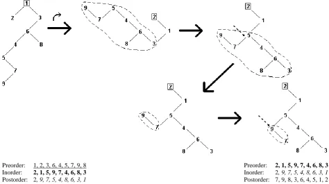
Figure 4 demonstrates the process of obtaining a roll of a binary tree using turning and downshift, after which the results are the same as in Figure 2b and Figure 2c. Figure 5 displays CCW() using turning and downshift in a tree in which the illusory ancestral stem contains more than one node, and therefore the illusory ancestor and the illusory root are different. Again, the linking of the true ancestor with the illusory root is the key to performing the downshift.
Depending on the internal structure (i.e. topology) of the tree, performing a roll operation using turning and downshift might
the appropriate definition for the corresponding roll operation (in Figure 6, the ending tree complies with definition (2), for clockwise roll).
[image:4.595.61.435.352.746.2]In most cases, the downshift is necessary if the roll operation gets performed visually using turning. However, there are cases when the downshift is not necessary, and the roll yields the same result as the turn, both visually and theoretically. Thus, CCW() is equal to a counterclockwise turn if no left sub-node in the tree has a right sub-node of its own (tree T1 in Figure 1 is such an example). Likewise, CW() is equal to a clockwise turn if no right node in the tree has a left sub-node of its own (tree T2 in Figure 1 is such an example).
It is worth mentioning that the turning and the downshift operations, as well as the notions of a wedge node, true ancestor, illusory stem of ancestors, illusory ancestor and illusory root, are visual only and don‟t actually take place or appear when performing the roll operations defined by definitions (1) and (2). However, they are useful for envisioning the roll processes and obtaining the rolled trees without first obtaining the traversals needed to generate them.
5.
MUTUAL INVERSENESS OF THE
ROLL OPERATIONS
From the definitions of CCW() and CW(), i.e. definitions (1) and (2), it follows immediately that both operations are inverse respective to one another (trees T1 and T2 in Figure 1 give a good visual demonstration of this property). As another example, if T1 is the tree represented in Figure 3a and T2 is the tree represented in Figure 3b, CCW(T1) = T2 and CW(T2) = Preorder: 1, 2, 4, 5, 8, 7, 9, 3, 6
Inorder: 4, 8, 5, 9, 7, 2, 1, 6, 3
Postorder: 8, 9, 7, 5, 4, 2, 6, 3, 1
[image:5.595.76.493.65.227.2]Preorder: 3, 1, 2, 7, 5, 4, 8, 9, 6 Inorder: 1, 2, 4, 5, 8, 7, 9, 3, 6 Postorder: 4, 8, 5, 9, 7, 2, 1, 6, 3
Figure 5: CCW() of a tree using turning and downshift. After the turn, the new root of the tree is ‘3’, the wedge node is ‘4’, its true ancestor is ‘2’, its illusory ancestor is ‘5’ and its illusory root is ‘7’, since the illusory ancestral stem of nodes consists of nodes ‘5’ and ‘7’. The downshift is performed by linking the true ancestor (‘2’) with the illusory root (‘7’), instead of the wedge node (‘4’), in the same direction of linking – the illusory root becomes the right sub-node of the true ancestor, just like the wedge node used to be. The traversals of the starting tree (bottom left) and the ending tree (bottom
[image:5.595.58.533.416.681.2](4)
6.
ALGORITHMS FOR THE ROLL
OPERATIONS
As a result of a roll operation on a given binary tree, a new binary tree gets produced, which contains all the elements of the original binary tree, but rearranged in a different hierarchical structure, so as to comply with definition (1) or (2), depending on the direction of roll. The most straightforward way to accomplish the roll in the desired direction is to obtain the traversals of the original tree and then reconstruct the new tree using the appropriate traversal combinations according to definition (1) or (2). However, since the tree obtained as the result of the roll always contains the same elements as the original tree, it is possible to generate an algorithm that will rearrange the elements so as to obtain the rolled tree without the need to obtain the traversals first. An algorithm for the roll operation will now be presented and explained.
Figure 7 shows the algorithm for CCW(). The algorithm is given in pseudocode, which most closely resembles the C++ programming language, and the lines are numbered, for a more detailed explanation. The algorithm is recursive and employs auxiliary variables defined within it, which are of the data type of a binary tree node. Normally, a node of a binary tree contains an information field, as well as links to the left sub-node and right sub-node of the same node type, called
lSn and rSn respectively in the pseudocode. The information field can be of any data type, and does not need to be comparable (i.e. does not have to have relation operators, such as >, <, == or !=, defined for it). The define directive will be used to define (i.e. declare and initialize) auxiliary variables. It is assumed that the node element type can be compared for equality and inequality to NULL (the null element, containing no information or value) and any other node element data type. The assignment operator (=) is also assumed to be defined for this node element data type. For clarity, the function header and the subsequent recursive calls within the algorithm are presented with bold letters.
Line 1 defines the function header. The function return type is not listed, as the algorithm itself does not produce a return value (if a return type would have to be listed, void would be a good choice). The parameters that are requested are the root of the tree (it is also used as the root of sub-trees in the subsequent recursive calls) and the root‟s predecessor, i.e. the node that had the root of the (sub-)tree as its sub-node. Initially, the predecessor node is NULL (and needs to be passed as such upon initial function calls), since the root of the original tree has no ancestor node. The values of both the
root and the predecessor nodes are guaranteed to
change within the function calls (since the roll operation requires that the root and the internal structure of the tree change so as to obtain the resulting tree) and that‟s why they are called by reference, as indicated by the ampersand (&) preceding them, indicating that the changes, that they‟ll be
7. root.rSn = root.lSn;
8. root.lSn = NULL;
9. CCW(root.rSn, root);
10. }
11. else
12. {
13. if(root.rSn.rSn == NULL)
14. {
15. root.rSn.rSn = root.rSn.lSn;
16. root.rSn.lSn = root;
17. root = root.rSn;
18. root.lSn.rSn = root.lSn.lSn;
19. root.lSn.lSn = NULL;
20. if(predecessor != NULL)
21. predecessor.rSn = root;
22. CCW(root.lSn.rSn, root.lSn);
23. CCW(root.rSn, root);
24. }
25. else
26. {
27. CCW(root.rSn, root);
28. define leftmost = root.rSn;
29. while(leftmost.lSn != NULL)
30. leftmost = leftmost.lSn;
31. leftmost.lSn = root;
32. define newroot = root.rSn;
33. root.rSn = NULL;
34. root = newroot;
35. if(predecessor != NULL)
36. predecessor.rSn = root;
37. CCW(leftmost.lSn, leftmost);
38. }
39. }
[image:6.595.314.521.90.575.2]40. } 41. }
Figure 7: The algorithm for the counterclockwise roll (i.e. the CCW() operation)
Line 3 gives the first test. The algorithm is designed to go through all nodes of the tree, so that the entire tree would be (recursively) rolled. Following some of the links (e.g. sub-nodes of leaves of the tree) will lead to NULL values, so the first test is for whether the algorithm will need to proceed at all. Should a NULL value be encountered, the algorithm (i.e. the current recursive call) ends immediately, as this first if test does not contain an else clause. This is actually the only trivial case in the algorithm and is thus used as the termination condition for the recursive calls.
The idea is that, upon CCW(), left sub-trees of the nodes become right sub-trees of the nodes. This is the first basic case, when there is no right sub-tree that needs to be processed, so the left sub-tree is put in its place and processed recursively.
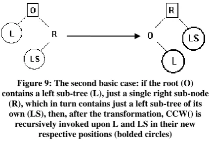
Lines 11 and 13 test for whether there is not more than one right sub-node. If so, this is the second basic case (presented visually in Figure 9). The left node of the root‟s right node will become the right node of the root‟s right sub-node (Line 15), whereas the left sub-sub-node of the root‟s right node will point to the root (Line 16). The root‟s right sub-node will become the new root (Line 17). Since the former root is now the left sub-node of the new root, whatever was present as its left sub-node (it may be NULL as well) is placed as its right sub-node (Line 18), and its left sub-node is set to NULL (Line 19). Since the root changes when this case is reached, the predecessor‟s right sub-node should also be changed to point to the new root, if the currently processed node (i.e. root) does have a predecessor (Lines 20 and 21). Finally, the new root‟s left sub-node‟s right sub-node can be processed recursively (Line 22), as well as the new root‟s right sub-node (Line 23), minding to include their respective predecessor nodes as parameters as well.
Line 25 introduces the most complex case, when the right sub-node has also a right sub-tree of its own (presented
Afterwards, CCW() is recursively invoked upon the former root in its new position (Line 37). Again, since the root changes when this case is encountered, the predecessor node needs to be taken into account and its right sub-node updated.
It may not be immediately apparent how the last case is connected to the roll operation. However, a closer look will reveal that it actually deals with the left downshift when CCW() is invoked upon stems of right sub-nodes (i.e. several nodes linked as right sub-nodes to one another). This case takes the root of the (sub-)tree and places it as the leftmost node of the root‟s right sub-node (which becomes the new root), but only after recursion calls have been invoked upon right sub-nodes progressively further down the stem, until one of the two basic cases, presented in Figure 6 and Figure 7, gets reached and handled. In this manner, a stem of right nodes will progressively become a reversed stem of left sub-nodes, connected to the leftmost node of the sub-tree obtained as a result of handling one of the basic cases. Thus, left downshift will be achieved after a counterclockwise turn, progressively and recursively, one root at a time.
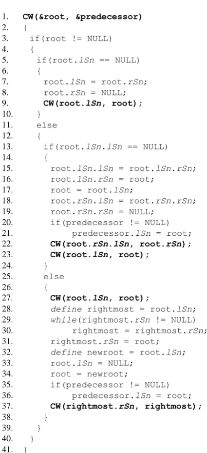
The algorithm for clockwise roll (i.e. CW()), presented in Figure 11, is a complete “mirror image” of the algorithm for CCW(). In fact, if everything “left” is replaced with “right” and vice versa in the CCW() algorithm, the CW() algorithm will be obtained (it is also necessary to replace “CCW” with “CW”). The procedure is completely analogous with the one for CCW().
7.
CONCLUSION
A new operation, called binary tree roll, has been proposed. The counterclockwise and clockwise roll of a binary tree have been presented and defined. It has been shown that they are proper operations, in a sense that their results are unambiguous, and that they change the internal structure of the tree. The concepts of turning and downshift have been
Figure 10: If the root (O) contains a right sub-node (RS) with a right sub-tree of its own (R), first CCW() is (recursively) invoked upon R, so it would be handled
by a basic case, or this same case (if R contains a right sub-tree of its own). Then, it is necessary to find the leftmost sub-node (LM) of the root’s right sub-node, i.e. of RS. In that case, O becomes the left sub-node of
LM, whereas the right sub-node of O is set to NULL (so as not to point to RS anymore), and RS becomes the new root. CCW() is then recursively invoked upon
[image:7.595.60.272.477.620.2]O in its new position (bolded circle)
Figure 9: The second basic case: if the root (O) contains a left sub-tree (L), just a single right sub-node
(R), which in turn contains just a left sub-tree of its own (LS), then, after the transformation, CCW() is recursively invoked upon L and LS in their new
respective positions (bolded circles)
Figure 8: The first basic case: if the root (O) contains just a left sub-tree (L), upon CCW() it becomes the right sub-tree, while the root’s left sub-tree is set to
8. root.rSn = NULL;
9. CW(root.lSn, root);
10. }
11. else
12. {
13. if(root.lSn.lSn == NULL)
14. {
15. root.lSn.lSn = root.lSn.rSn;
16. root.lSn.rSn = root;
17. root = root.lSn;
18. root.rSn.lSn = root.rSn.rSn;
19. root.rSn.rSn = NULL;
20. if(predecessor != NULL)
21. predecessor.lSn = root;
22. CW(root.rSn.lSn, root.rSn);
23. CW(root.lSn, root);
24. }
25. else
26. {
27. CW(root.lSn, root);
28. define rightmost = root.lSn;
29. while(rightmost.rSn != NULL)
30. rightmost = rightmost.rSn;
31. rightmost.rSn = root;
32. define newroot = root.lSn;
33. root.lSn = NULL;
34. root = newroot;
35. if(predecessor != NULL)
36. predecessor.lSn = root;
37. CW(rightmost.rSn, rightmost);
38. }
39. }
[image:8.595.52.265.77.542.2]40. } 41. }
Figure 11: The algorithm for the clockwise roll (i.e. the CW() operation)
8.
REFERENCES
[1] Sedgewick, R. 1998. Algorithms in C++, Parts 1-4: Fundamentals, Data Structures, Sorting, Searching. Addison-Wesley.
[2] Brassard, G. and Bratley, P. 2002. Fundamentals of Algorithmics. Prentice Hall of India
[3] Bozinovski, A. and Bozinovski, S. 2004. N-queens pattern generation: An insight into space complexity of a backtracking algorithm. In Proceedings of the 3rd International Symposium on Information and Communication Technologies. Las Vegas, Nevada, USA, 281-286
Code Project.
http://www.codeproject.com/KB/recipes/BinaryTree.asp x. Accessed 10 January 2012
[7] Kruse, G. W. 2007. Binary Tree Operations. CS240: Computer Science II. Department of Information Technology and Computer Science. Juniata College. http://jcsites.juniata.edu/faculty/kruse/cs240/bintree.htm. Accessed 10 January 2012
[8] Sleator, D. D., Tarjan, R. E., and Thurston, W. P. 1988. Rotation distance, triangulations, and hyperbolic geometry. Journal of the American Mathematical Society. Vol 1. No 3. 647-681
[9] Chen, W. Y. C. and Yang, L. L. M. 2008. On Postnikov‟s hook length formula for binary trees. European Journal of Combinatorics. Doi: 10.1016/j.ejc.2007.11.025
[10]Doshi, N., Sureja, T., Akbari, B., Savaliya, H., and Daxini, V. 2010. Width of a Binary Tree. International Journal of Computer Applications. Vol 9. No 2. 41-43 [11]Arora, N., Tamta, V. K., and Kumar, S. 2012. Modified
Non-Recursive Algorithm for Reconstructing a Binary Tree. International Journal of Computer Applications. Vol 43. No 10. 25-28
[12]Zhou, A., Huang, S., and Wang, X. 2007. BITS: A Binary Tree Based Web Service Composition System. International Journal of Web Services Research. Vol 4. No 1. 40-58
[13]Duarte, E. P. Jr, Pires, K., and Tavares, R. A. E. 2010. An efficient strategy for storing and searching binary trees in WORM external memory. Journal of Information Science. Vol 36. No 6. 751-762
[14]Wang, D., Zheng, J., and Zhou, Y. 2011. Binary tree of posterior probability support vector machines. Journal of Zhejiang University – Science C. Vol 12. No 2. 83-87 [15]Burgdorff, H. A., Jajodia, S., Springsteel, F. N., and
Zalcstein, Y. 1987. Alternative methods for the reconstruction of trees from their traversals. BIT Numerical Mathematics. Vol 27. No 2. 133-140 [16]Narahari, Y. 4.2 Binary Trees. Data Structures and
Algorithms. Computer Science and Automation. Indian
Institute of Science.
http://lcm.csa.iisc.ernet.in/dsa/node87.html. Accessed 10 January 2012