© 2017, IRJET | Impact Factor value: 5.181 | ISO 9001:2008 Certified Journal | Page 998
AN ANALYSIS OF MULTI-STOREY BUILDING WITH FLOATING AND NON
FLOATING COLUMN UNDER SEISMIC LOADING IN DIFFERENT ZONES.
Mohd. Azaz
1, Amarnath D. Burde
2, Mohd. Yasin sheikh
3, Lehazuddin Quazi
41
Assistant professor, Dept. of Civil Engineering, Anjuman College of engineering and technology, Maharashtra,
India
2
Student of Graduation, Dept. of Civil Engineering, Anjuman College of engineering and technology, Maharashtra,
India
3
Student of Graduation, Dept. of Civil Engineering, Anjuman College of engineering and technology, Maharashtra,
India
4
Student of Graduation, Dept. of Civil Engineering, Anjuman College of engineering and technology, Maharashtra,
India.
---***---Abstract
- Floating columns are a typical feature in the modern multistory construction in urban India and are highly undesirable in buildings built in seismically active and inactive zone areas. The present study investigates the effects of the structural irregularity which is produced by the discontinuity of a column in a building subjected to seismic loads in diff. zones. In this paper static analysis and conventional analysis using equivalent static method is done for a multistory building with and without floating columns in seismic zone-II & zone-V. Different cases of the building are studied by varying the location of floating columns floor wise, setback column and within the floor. The structural response of the building models with respect to Fundamental time period, Base shear, Storey drift and Storey displacements is investigated. The analysis is carried out using software STAAD Pro V8i software.Keywords—Floating columns, static analysis, Base shear, earthquake zone.
1. INTRODUCTION:
Today many multi-storeyed buildings in India have floating columns as an unavoidable feature. This is being adopted- a) to provide more space in ground floor for accommodation of parking or ground lobbies b) for architectural beauty c) to increase floor space index.
Floating columns in a building may result in a concentration of forces or deflection or in an undesirable load path in the vertical lateral-force-resisting system. In extreme cases, this can result in serious damage or collapse of the building, since the lateral load resisting system is often
integral with the gravity load resisting system. Vertical irregularities typically occur in a storey that is significantly more flexible or weaker than adjacent stories. Many buildings with vertical discontinuities collapsed or were severely damaged during the 2001 Bhuj earthquake in Gujarat.
Thus, buildings with columns that hang or float on beams, at an intermediate storey and, do not go all the way to the foundation, have discontinuities in the load transfer path. This paper presents the results of investigation of structural response quantities of a multi-storeyed building with floating columns.
Fig. 1. Building with floating column
(a) floating column: the column is discontinued at a lower level, and (b) set-back column: the column is moved out of
© 2017, IRJET | Impact Factor value: 5.181 | ISO 9001:2008 Certified Journal | Page 999
Fig :2
Elevation
I. OBJECTIVES
The primary objectives of the study are as under –
1. To study the behavior of multi-storied buildings with floating & setback columns under earthquake excitations. 2. To carry out Static and conventional gravity analyses for different cases by varying the location of floating columns floor wise and within the floor.
3. To model the building using software STAAD PRO V8i for analysis and design purpose.
4. To study the structural response of the building models with respect to following aspects –
1.Shear force and Bending Moment 2. Base shear.
3. Storey Displacement. 4.Story Drift
II. MODEL STUDIES
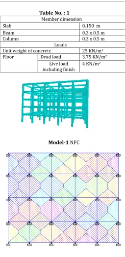
A 22.786m x 21.83m multi-storied building (B+G+3), with special moment resisting frame was selected for study. It was considered to be located in Zone II & another model located in Zone-V on Type II(medium) soil. The loads and member sizes are summarized in Table I. In this study first a non floating Column and any floating column is modeled whose floor elevations are shown in figure 2. Then, two types of models, namely 2 and 3 are modeled. In model 2, the floating columns are located at basement ground floor and in model 3 they are located at third floor& ground floor. For each model three different cases are studied with diff. zones. Displacement, Base Shear And Bending Moment.
Building Data
:Table No. : 1
Member dimension
Slab 0.150 m
Beam 0.3 x 0.5 m
Column 0.3 x 0.5 m
Loads
Unit weight of concrete 25 KN/m3
Floor Dead load 3.75 KN/m2
Live load
including finish 4 KN/m 2
Model-1
NFC
Fig 3
Plan with slab Load distribution
III. MANUAL CALCULATION
The total seismic weight of the structure is calculated by using IS-1893 2000.The Model with Non Floating Column is manually calculated for Base Shear, Bending Moment & Shear Force. Manual result are compared with staad result for validation of models.
[image:2.595.49.275.115.283.2]© 2017, IRJET | Impact Factor value: 5.181 | ISO 9001:2008 Certified Journal | Page 1000 Fundamental time period :- 0.075h0.75
TABLE-2:
COMPARISION FOR
MODEL VALIDATION
Model-1
NFC(Manual)
Model-2 NFC
(Staad)
Base Shear
685 KN
687 KN
BM
170 KN-m
174.47 KN-m
Model-2
FLOATING COLUMN 1
Model-3
FLOATING COLUMN 2
LOAD COMBINATIONS CONSIDERED FOR THE
BUILDING ANALYSIS
The shown load combinations are adopted for the design and analysis of the structure according to the code IS 1893 (part I) : 2002
Table:- Load combinations as per IS 1893(Part1):2002
Where,
DL= Dead load LL = Live load .
EQX,EQY= Earthquake load in the X and Y directions ,
respectively
TABLE-3:
LOAD COMBINATION
IV. RESULT
In the present work, the structural displacement of column in RC building on with respect to base shear and displacement using equivalent static analysis.
The result are compare in tabular form and graphically.
TABLE-4:
DISPLACEMENT (mm)
Model Name
X-Direction
Z-Direction
NFC M1 Z-II 10.84 20.79
FC M2 Z-II 13.89 22.83
FC M3 Z-II 11.85 18.93
NFC M1 Z-V 38.88 74.71
FC M2 Z-V 46.15 82.32
FC M3 Z-V 40.82 68.07
0 10 20 30 40 50 60 70 80 90
NFC M1 Z-II
FC M2 Z-II
FC M3 Z-II
NFC M1 Z-V
FC M2 Z-V
FC M3 Z-V
X DIRECTION Z DIRECTION
DISPLACEMENT (mm)
SR
NO.
Load
Combination
Load Factors
1.
Gravity
analysis
1.5(DL+LL)
2.
Equivalent
static
analysis
© 2017, IRJET | Impact Factor value: 5.181 | ISO 9001:2008 Certified Journal | Page 1001
TABLE-5
: BASE SHEAR (KN)
ZONE
MODEL
NAME
BASE SHEAR
II NFC M1 687
II FC M2 685
II FC M3 541.1
V NFC M1 2470
V FC M2 2465
V FC M3 1948.1
0 500 1000 1500 2000 2500 3000
NFC M1 Z-II
FC M2 Z-II
FC M3 Z-II
NFC M1 Z-V
FC M2 Z-II
FC M3 Z-V
BASE SHEAR
BASE SHEAR
MODEL NAME
+VE
-VE
NFC M1 Z-II 174.47 102.198
FC M2 Z-II 174.4 102.22
FC M3 Z-II 165.75 78.05
NFC M1 Z-V 313.94 126.23
FC M2 Z-V 322 129.34
FC M3 Z-V 282.6 115.7
01020304050607080901stQtr2ndQtr3rdQtr4thQtrEastWestNorth
TABLE-6
: BENDING MOMENT (KM-m)
050100150200250300350NFC M1 Z-IINFC M1 Z-+VE -VEBENDING MOMENT (KN-m)
V. CONCLUSION
1.
It was observed that in building with floating
column there is an increase in fundamental
time period in both X-direction as well as
Z-direction as compared to building without
floating column.
2.
In an earthquake prone region (Zone V)
which is coming Zone V. It not advisable to
provide floating column. As we can see in the
above result displacement is very high.
3.
By introduction of floating column in a
building base and spectral acceleration
decreases. Thus, It has this technical &
functional advantage over conventional
construction.
4.
As from Displacement of our result on
floating an also high so in order to improve
its performance during earthquake it is
necessary for certain remedial measuring like
Shear Wall, Retrofitting, Steel jacketing.
REFERENCES:
1.
IS:1893 (part1) 2002, Criteria for Earthquake
Resistance Design of Structures, part
1-General provisions and buildings, fifth
revision, Bureau of Indian Standard, New
Delhi, India
2.
Agarwal Pankaj, Shrikhande Manish (2009),
“Earthquake resistant design of structures”,
PHI learning private limited, New Delhi ,India
3.
C.V.R. Murty, "Earthquake tip 6,
IITK-BMTPC", Indian Institute of Technology,
Kanpur, India 5.
4.
A.P. Mundada, and S G Sawdatkar,
“Comparative seismic analysis of multistory
Building with and without floating column”.
5.
A Textbook on “Reinforced Concret Design
© 2017, IRJET | Impact Factor value: 5.181 | ISO 9001:2008 Certified Journal | Page 1002
BIOGRAPHIES
Prof. Mr Mohd Azaz,
(M.Tech-Structural Engineering)
Mr. Amarnath D Burde, Student of Graduation, Nagpur University.
Mr. Mohd Yasin Sheikh, Student of Graduation, Nagpur University