SYS68K /WFC-l
NOT E
The information in this document has been carefully checked and
is believed to be entirely reliable. FORCE COMPUTERS makes no
warranty of any kind with regard to the material in this
document, and assumes no responsibility for any errors that may
appear in this document. FORCE COMPUTERS reserves the right to
make changes without notice to this, or any of its products, to
improve reliability, performance or design.
FORCE COMPUTERS assumes no responsibility for the use of any
circuitry other than circuitry which is part of a product of
FORCE COMPUTERS GmbH/Inc.
FORCE COMPUTERS does not convey to the purchaser of the product
described herein any license under the patent rights of FORCE
COMPUTERS GmbH/Inc. nor the rights of others.
FORCE COMPUTERS Inc. 727 University Avenue Los Gatos, CA 95030 U.S.A.
Phone Telex FAX
(408) 354 34 10 172465
(408) 395 77 18
FORCE COMPUTERS GmbH Daimlerstrasse 9
D-80l2 Ottobrunn/Munich West Germany
Phone Telex FAX
(089) 600 91-0 524190 forc-d
1.13 2.13 2.1 3.0 3.1 3.2 3.3 3.4 3.5 3.6 3.7 3.8 3.9 3.113 ·3.11 3.12 4.0 4.1 4.2 4.3 4.4 4.4.1
Table of Contents
General Information
General Operation
Features of the SYS68K/WFC-l
Hardware Overview
Global Base Address Selection
Address Modifier Decoding
Interrupt Jumpering
Connectors Organisation
Winchester Drive Control Signals
Winchester Control Connectors
Winchester Drive Data Connector
Floppy Drive Signals
Floppy Drive Control Connector
Run/Local Switch
LED Indicators
Access Times
SYS68K/WFC-l Register Set
Register Set Basics
Address Map
Data Register
Error Register
Diagnostic Errors
Table of Contents contd.
-
Page4.10 Status Register 47
4.11 Command Register 48
4.12 Interrupt Vector Registers 48
5.0 Commands 49
5.1 General 49
5.2 Commands Summary 49
5.3 Type I Commands 51
5.3.1 Test 51
5.3.2 Restore 51
5.3.3 Seek 52
5.4 Type II Comands 52
5.4.1 Read Sector 52
5.4.1.1 DMA Read 53
5.4.1.2 Normal Completion 53
5.5 Type III Comands 53
5.5.1 Write Sector 54
5.5.2 Format Track 54
6.0 Progranuning 55
6.1 General 55
6.2 Setting Register Set 55
6.2.1 Cylinders 'and Tracks 56
6.3 Type I Command programming 56
6.3.1 Use of Busy Bit 57
6.3.2 Use of Interrupts 57
6.3.3 Use of the Error Bit 57
6.4 Type II Commands 58
Table of Contents contd.
6.5 Type II Cormnand Programming
6.5.1 Formatting
6.5.2 Interl~aving
6.6 Prograrmning Examples
6.6.1 Read
6.6.2 \'lri te
APPENDIX "A"
APPENDIX "B"
APPENDIX "C"
APPENDIX "D"
APPENDIX "E"
Sector
Sector
Specification of the
SYS68K/vWC-l-Address Map of the SYS68K/WFC-l
SYS68K/WFC-l' Component Part List
Circuit Schematics
Data Sheets \vD10l0
\vD1014 WD101S WD2797
Page
59 59 60
61
61
62
A-l
B-1
C-l
n-l
E-l
Fig.1 Fig.2 Fig.3 Fig.4 Fig.5 Fig.6 Fig.7 Fig.8 Fig.9 Fig.10 Fig.ll
Table 1
Table 2
Table 3
Table 4
Table 5
Table 6
Table 7
Table 8
Table 9
Table 10
Table 11
Table 12
List of t:!.9.~~f!.~
Photo of Board
Board Block Diagram
Jumper Field for Base Address Selection
Location of the Base Address Jumper Fields
AM Jumper Fields
Interrupt Jumper Fields
Location of the Interrupt Jumper Fields
Connectors Location Diagram
Front Panel of the SYS68K/WFC-l
Data Transfer Bus Read Cycle Timing
Data Transfer Bus Write Cycle Timing
List of Tables
Address Modifier Codes
Winchester Drive Control Connector Pin Description
Winches~er Drive Data Connector Pin
Description
Floppy Drive Control Connector Pin Description
Data Transfer Bus Read Time Values
Data Transfer Bus Write Time Values
SYS68K/WFC-l Address Map
Error Register Bits
Size Drive Head Register
Command Types
Stepping Rates
Interleave Table
1.0 General Information
The SYS68K/WFC-l is a high performance VMEbus interface
controller board to control 5 1/4" Floppy and Winchester drives.
The SYS68K/WFC-1 board has been developed to serve as a
controller board for high speed data transfers to and from 5 1/4"
Floppy and Winchester drives via a 1 KByte FIFO buffer~ The
board can communicate with a DMA controller to provide maximum
bus transfer speed and is able to generate interrupts for
complete operation, error operation and data request.
The VMEbus allows easy system design with extended
r/o,
RAM, CPU,.ROM, and DMA cards.
This manual provides a general operating description of the
SYS68K/WFC-l hardware. Follow manufacturer's installation
SYS68K/WFC-1
:!!
G> I\)
I
SWITCHES LEOS IU
INTERNAL CONTROL BUS
OJ 0
»
JJ 0 OJ5
J
~1
~1
L:=
..--- BOARD
r - CONTROL
ERROR LOGIC
SECTOR BUFFER
BUFFER CONTROLLER AND CORRECTOR CHECKING
0 J. ~
;;wi;
0
»
~
r
II
II
G> JJ
»
s::
en
~.7
....tJ;..
~~
A
-<
...
en
lSI (» 0>
~
~
I....I.
FLOPPY WINCHESTER INTERRUPT
CONTROlLER CONTROLLER ,--l\ CONTROL
'f
rv'
LOGIC rJ)::l
m
~').
-<J
r-- ..J rJ).;/. 0 ::l
~~
m ~... 'I"
..
~ ADDRESSc(
Iv-
0DECOOER
FLOPPY WINCHESTER
INTERFACE INTERFACE
·t
L4'"">-ADDRESS BUS
IFD
CONTROl/DATA FCI
I
I
WD CONTROL FCI
"'= ~ ~ ;..
I WD1 DATA Fe I I WD2 DATA FC
I
I
WD3 DATA FC II
VME BUS INTERFACEI
/ '
~
J
ADDRESS BUS2.0 General Operation
The SYS6aK/WFC-I consists of a set of devices specifically
designed for control of Winchester and Floppy disk drives. The
heart of the control logic is the Control Processor Buffer
Manager .(WDI0lS) that manages the on-board static RAM sector
buffer (204a-word by a-bit). All bytes of data written to and
read from disk are first stored on this sector buffer. vfuen the
buffer is full, the data is transferred, on command, to its
intended destination.
The WD10lS, besides controlling the data flow between host,
sector buffer, and disk controllers, also translates the host
Winchester command format to Floppy disk format when addressing
the Floppy Disk Controller (WD2797). This permits the host to
maintain a single command format (Winchester) while in effect
controlling two different disk command formats (Winchester vs.
Floppy). This is possible, since the SDH register is used to
select either type of drive.
The WD101S maintains the current copies of necessary host command
data in the task files: a set of register physically located in
the Winchester Disk Control device (WD1010) and the Error
Detection and Support logic device (WD1014).
The WD10l0 is the link between the host processor (via sector
buffer) and the Winchester disk drives. During transfer of data
from the host to the WD1010, the WD10l4 computes a 4-byte ECC
which is appended to the end of the data being transferred to the
WD10l0 and recorded on the disk. During data transfers from
WD10l0 to the host (via the sector buffer), the WD10lS uses the
BeC syndrome to validate the data. Retries and corrections are
attempted automatically in case of corrupted data.
The WD101S performs error correction in conjunction with the
WD1014 on data transferred to the' disk. While the WDl0lS
controls the operation of the on-board error-correction logic,
the WDl0l4 generates and checks the Error Correction Code (ECC)
if SDH bit 7
=
0. Thus the WDl0l4 also provides the WDl0lS withits real-time control capability.
If CRC format Winchester disks are used, CRC is selected by the
WD1010 by setting SDH7
=
0. CRC for the floppy disk is performedby the WD2729, a device that furnishes all control functions for
floppy disk drives, including necessary data seperation and write
- Fully VMEbus compatible
- Jumper selectable base address with address modifier
Generation at two different interrupts
- Jumper selectable interrupt level
- Software programmable interrupt vectors
Three VMEbus options· (A31:D16), (A23:D16), (A15:D16) jumper selectable
- User selectable 5.25" Winchester or Floppy operation
- Controls up to 3 Winchester ST506 Interface and up to 4 Floppy
drives SA450 compatible
- On-board data seperation circuitry
- On-board write precompensation for floppy and hard disks
- On-board sector buffer supports up to 1 KByte sectors
- Programmable sector sizes - 128, 2.56, 512, or 1024 bytes
- Automatic track formatting on hard and floppy disks
- Multiple sector operations on all disks
- Data rates up to 5 1'1bits/ sec on hard disk
- Single burst error correction up to 5 bits on hard disk data
- eRe
generation/verification for ·data and all I.D. fields- Automatic retries on all errors with simulated completion
ECC diagnostic commands included (READLONG & WRITELONG)
- Internal diagnostics
3.0 Hardware Overview
3.1 Global Base Address Selection
The SYS6BK/WFC-l controller board contains a set of jumper fields for the global base address selection.
This board contains also two jumper fields, BRe and BR9, for the
VMEbus options (A1S-D16), (A23-D16) and (A31-D16), (see Fig. 3).
The following table shows the connection of BRe and BR9 for these options :
BRB BR9
CONNECTIONS CONNECTIONS OPTIONS
1 to 2 1 to 2 A15:D16
1 to 2 2 to 3 A23:D16
2 to 3 2 to 3 A32:D16 y
No other combination is allowed, as it may cause errors in the
system.
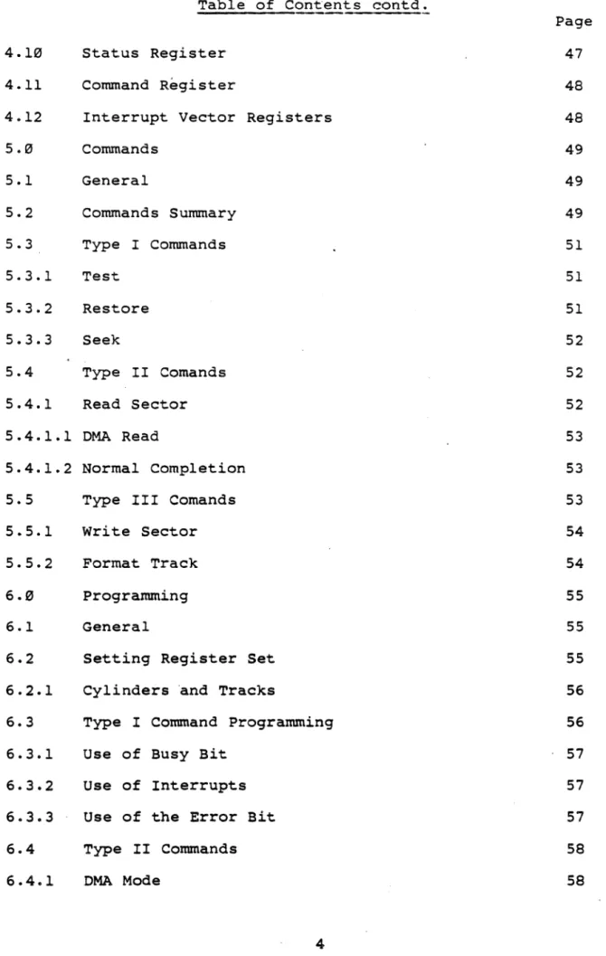
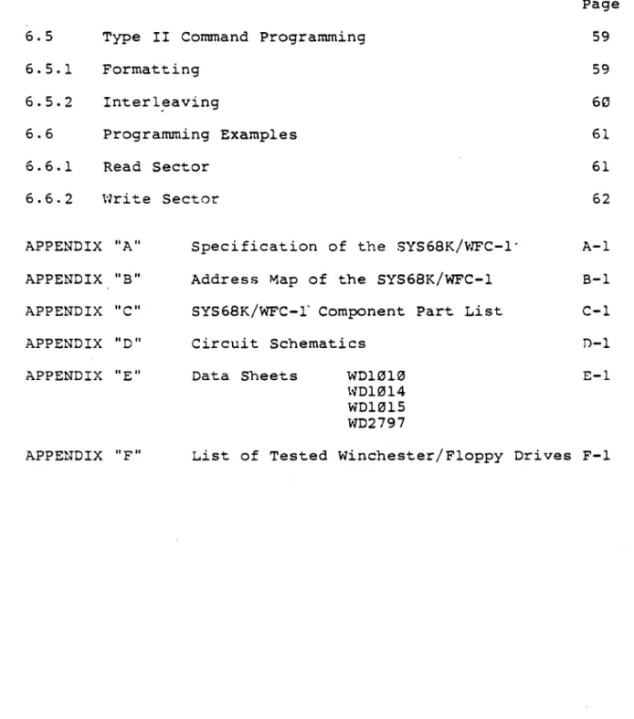
The address signals A3l-A4 are used for the global base address
selection. Fig.3 shows the jumper location and the default
setting during manufacturing ($B01000) for the A23:D16 option.
For all of these jumper fields, jumper in means 0 for the
corresponding signal and jumper out means 1 for the corresponding
signal. Fig. 4 shows the physical location of these jumpers on
t
r
i
i
I
I
+0 c: 1i
Nh!
n~w
j .. I)-
-r
~,J.~
I
Otill!
O!IJDD
~8
r
-~
,
~3'~" "'.0
,
_'11LPO
.
01 •
.
.
"1.
P2 Q'l • "3 Q
£
.
P~ Q<O ~~P5
~
II:
o...J,;i. '"
"
c
. , .. ,
.
...
(j)
0
...J
W
LL
J17
a:
W
a..
J18 ~
:::>
J
124 (j)
(j)
W
a:
129 0
0
<{
HZ W
(j)
<{
OJ
til
W r-i
I
l-LL
a
J"
z
a
J47
~
0
a
J50 ...J
J49 1)1
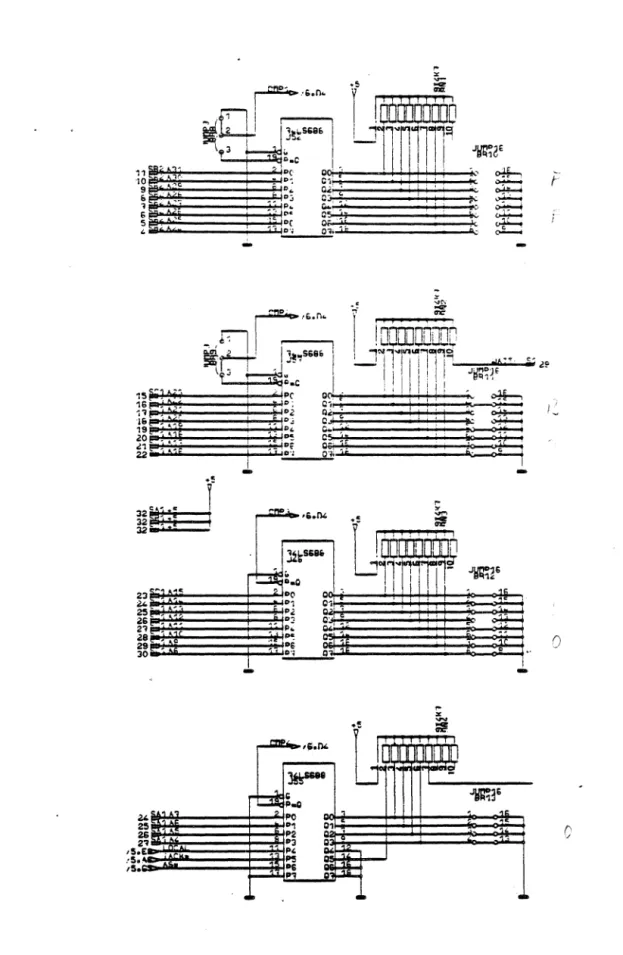
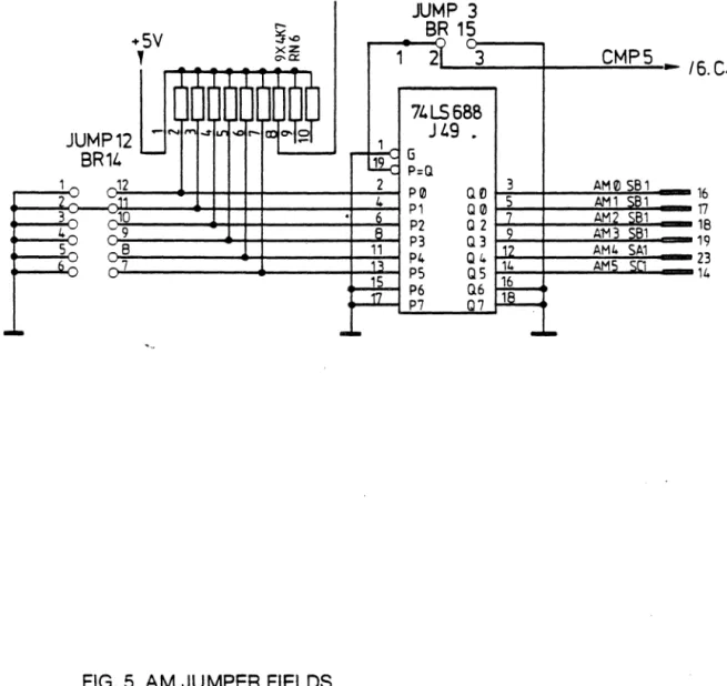
The address modifier (AM) signals of the VMEbus may be used for
additional decoding in parallel to the address signals.
Table 1 lists the combination of the AM signals and the relevant
functions.
The BR1S may be jumpered so ~hat these signals are
(don't care). If BRlS pin 1 is connected to pin 2,
decoding is enabled. If BRlS pin 2 is connected to
the ~ decoding is disabled.
The BRl4 jumper field includes the AM code and Fig.
example for supervisor data decoding. Fig. 4 shows
location of the BRl4, BRlS jumper field on the
board.
not decoded
then the AM
pin 3, then
S shows an
--
--FIG. 5 AM JUMPER FIELDS
JUMP 3
BE
15
, . . - - - - 0 0 - -...
1
21
-3
CMP5 _ 16.CI.a.
fJ J-:;-3 ~_--:;A?-:M~0~ 18~1 _ _ 16Q0 5 AM1 iS1 17
Q 2 7 AM2 581 18
0.3 9 A"M3 81 19
12 AM4 SA1
Q 4 14 AMS SCl 23
a.
5 16 14~~
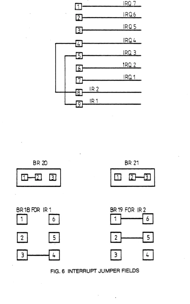
18--3.3 Interru~~~~~S
The SYS68K/WFC-l controller board can generate two
interrupts. The first interrupt, IRI, is for operation
and error operation.
different complete
The second interrupt, IR2, is for data request by read, write and
format operations, if the controller board needs data or has to
send data.
Both interrupts can be enabled and disabled seperately and can be jumpered on each interrupt level on the VHEbus.
IRI can be enabled via BR20 through connection pin 1 to 2 and IR2
via BR21 through connection pin 2 to 3.
If BR20 pin 2 is connected to pin 3, then the operation complete
interrupt is disabled. If BR21 pin I is connected to pin 2, then
the data request interrupt is disabled.
The interrupt request level can be selected via jumper field
BRI6.
Fig. 6 shows the jumper fields and an example for enabled
interrupts for a connection to the interrupt level 3 for IRI and
to the interrupt request level 4 for IR2. BRl8 and BRl9 must be
selected to the corresponding level (see Fig. 6). Fig. 7 shows
the physical location of these jumpers on the controller board.
The interrupt default setting by manufacturing is disabled and
IlEXADECIMAl ADDRESS MODIFIER FUNCTION DEFINED
CODE 5 4 3 2 1 0 BY
:)
<II » 3S:
3F H H H H H H Standard Supervisory Ascending Access VMEbus Spec.
3E H H H H H l Standard Supervisory Program Access VMEbus Spec.
0 0
0-<II
1/1
I» -i
..., I» <II 0<
-I» <II
=- ...l
0-30 H H H t-t l H Standard Supervisory Data Access VMEbus Spec.
3C H H H H l l Undefined Reserved
3B H H H l H H Standard Non-Privileged Ascending Access VMEbus Spec.
3A H H H l H l Standard Non-Privileged Program Access VMEbus Spec.
39 H H H l l H Standard Non-Privileged Data Access VMEbus Spec.
38 H H H l l l Undefined Reserved
::;;»
mO-
:Do-30-- 37 H H l X X X Undefined Reserved
2F H l H H H H Undefined Reserved
--& ..,
Olm
iii" 1/1
o 3S: o 0 ...
::J
0-\D
::J ::;; <II _.
!l~
<II 0
no - n
a
m
3
2E H l H H H l Undefined Reserved
20 I-I l H H l H Short Supervisory I/O Access VMEbus Spec.
2C H l H H l l Undefined Reserved
2B H l H l H H Undefined . Reserved
2A H l H l H l Undefined Reserved
29 H l H l l H Short Non-Privileged I/O Access VMEbus Spec.
28 H l H l l l Undefined ~ Reserved
20- 27 H l l X X X Undefined Reserved
:::9. 10-1F l H X X X X Undefined User
::J
OF l l H H H H Extended Supervisory Ascending Access VMEbus Spec.
BR 20
BR18 FOR IR 1
OJ
m
W
IT]
[D--[I]
BR 16
OJ
(i]
[IJ
II]
rn
IRQ 7
IRQ6
IRQ 5
IRQ4
IRQ 3
'RQ 2
IRQ1
IR 2
IR 1
BR 21
1m liJ-ffi1
BR 19 FOR IR 2
QJ---0
[I}---ITJ
o
[IJ
~
0
JlI
ell
15 JI
en
0J9 ..J
W
RNa CJI JI5
~
rt----~----I
J20 :;; <:11 JII
,-
.
-~.
127~
l
8RILfuR/_l
mI
I
60
1-
IF"
I
01 Jl7
~17r-"'1 :; C19 J12
}~ L_~
l
159?l 8Rll RNIO
-m5
IC]6
C 14Rll
t>
D=
15 125 126IT:
a::.
w a..
~ :J ...,
li:
:J
a::.
a::.
w
~
W ..-t
I N
r
L.~---r..---~ r[---J
lr=CJr29'---~J]~5 ~ Jl6
n.
1 '"
..
.,
I
~
,n
I:J
JUill -
~
"Wil
11111111111111111111
t..
..
t.
I;
ElIIIIIIIIIIIIIIII
RFl
RNa [2~---150---I
Sf] t j C j J41 J49
r::J26 RHlb
J47
u.. 0 Z 0
5
0
..J
\'-3.4 Connectors' Organisation
The SYS68K/WFC-l has seven'connectors for user applications:
- Two VMEbus connectors SXl and SX2
- S7 Winchester drive control connector
- S8 Floppy drive control connector
- ST1, ST2, ST3 Winchester high speed data connectors
STl
=
LUN 0ST2
=
LUN 1ST3
=
LUN 2The drive control cables are daisy-chained to each of the three
Winchester drives. The three drive data connectors carry
differential signals and are radially connected.
The following diagram shows the physical location of the
BR21
- - - -. . ,---TT---~BR~201t==~t=~~~ [ ]
[] ~ ~
en
JI J9
J15
RNI
B
JII120 .. ~ J2 2 ~ ~ J2)
~~~----Il-=~~_.r_~============t
J21 u~~~~====~
~
r---t::="~r:
t
I
:m
m"1' "
m~~~~tm
I
q][
I,.
))6
e29 us C49
U
I
U
J44q
~ =:JU~
.. I
8L
'''8L .,
UI
I~
l
II1I1111111
n
11111 III III
III
J45n
J46~SIJ4--1
--niiii'fC5L--J
-49
-=
J50
St··· ..
>··
· . / ; : ' . / . 1
tE
RN9e2
Cli
C6
J24
J29
J47
:?!
«
a:
(!)
«
0
z
0
~
() 0
....J
CJ) M
a:
C\I0 t-O
w Z Z
0
0
CO
(!)
3.5 Winchester Drive Control Signals
The Winchester Drive Control connector S7 is a relatively
low-speed bus, daisy chained to each of the Winchester drives in the
system. To properly terminate the open collector outputs from
the SYS68K/WFC-l, the last drive in the daisy chain should have a
220/3300Hm line termination resistor pack installed~ All other
drives shoud have no termination. Drive control signals are as
follows
RWC* When the Reduce Write Current (RWC*) line is activated
with write gate, a lower write current is used to
compensate for greater bit-packing density on the inner
cylinders. The RWC* line is activated when the cylinder
number is greater than or equal to four times the
contents of the write precomp register. This output is'
valid only during write and format commands.
WG* The Write Gate* signal enables the disk write data
circuitry.
SC*
TR000*
Seek Complete* line informs the SYS68K/WFC-l that the
head of the selected drive has reached the desired
cylinder and has stabilized. Since Seek Complete* is
not checked after a seek command, overlapped seeks are
allowed.
Track 303* indicates that the R/W heads- are positioned
on the outermost cylinder. This line is sampled before
each step pulse is issued.
Write Fault* informs the SYS68K/WFC-l that some fault
has occurred on the selected drive. The SYS68K/WFC-l'
will not execute commands when this signal is true.
HS2-rIS3* Head Select lines (HS2-IIS0)* are used by the
SYS68K/\-JFC-1 to select a specific R/W head on the selected
Winchester drive.
IND*
ROY
*
Index* is used to indicate the index point for
synchronization during formatting and as a time-out
mechanism for retries. This signal ahould pulse once
every rotation of the disk.
Ready* informs the SYS68K/WFC-l that the desired
is selected and that its motor is up to speed.
SYS68K/WFC-l will not execute commands unless this is true.
STEP* Step* is pulsed once for every cylinder to be steppen.
The direction of the step will be determined by the
direction line. The Step* pulse period is determined by
the internal Winchester stepping rate register during
implied seek operations, or explicitly during seek
command~. During auto-restore, the step pulse period is
determined by the seek complete time from the drive.
DSl-DS3* These three Drive Select* lines (DSI-DS3) are used to
select one of three possible drives.
DIRIN* Direction-In* determines the direction of motion of the
R/W head when the step line is pulsed. A high on this
3.6 5.25" vlinchester 34-pin Drive Control Connector
This drive control connector S7 is a 34-pin vertical header on
0.l0-inch centers. Cabling should be flat ribbon or twisted-pair
cable less than 10 feet long. The cable pinou.ts are given in
Table 2.
Signal
1
Signal I/O Signal Name1
I Ground 1 Pin 1 1 I
1---1
1 . 1 11 1 2 0 1 RWC* I
1 1
1 3 4 0 Head Select 2* I
I 1
1 5 6 0 Write Gate* 1
1 1
1 7 8 I Seek Complete* I
I 1
1
9 10l
TR000*1
I 1
I
11 12 I Write Fault*I
I - 1
I
13 14 0 Head Select 0*I
1 1
I 15 16 NC 1
I 1
I
17 18 0 Head Select 1*I
1
19 20 I Index* 1
I
21 22 I Ready*
I
I
23 24 0 Step*
I
I
25 26 0 Drive Select 1*
I
I
27 28 0 Drive Select 2*
I
I
29 30 0 Drive Select 3*
I
I
31 32 NC
I
I
33 34 0 Direction-In*
I
I
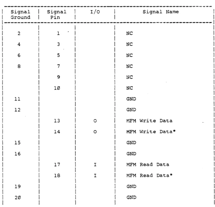
---3.7 Winchester Drive Data Connector
Three data connectors (ST1-ST3) allow data to pass between the
SYS68K/WFC-l and each Winchester disk drive. All lines
associated with the transfer of data between a drive and the
SYS68K/WFC-l are differential in nature and may not be
multiplexed. The three Winchester drive data connectors are
20-pin vertical headers on 0.10" centers. Cabling should be either
flat ribbon or twisted-pair cables, less that 10 feet long.
Cable pinouts are given in Table 3.
Table 3. Winchester Drive Data Connector Pin Description
I
Signal SignalI
I/O Signal NameI
I Ground I Pin I 1 1
1---1
2 1 NC
4 3 NC
6 5 NC
8 7 NC
9 NC
10 NC
11 GND
12 GND
13 0 ~1FM Write Data
14 0 MFM \vri te Data*
15 GND
16 GND
3.8 Floppy Drive Signals
The Floppy Drive Control Connector S8 is a relatively low-speed
bus, daisy chained to each of the floppy drives in the system.
To properly terminate each TTL-level output signal from the
SYS68K/WFC-l, the last drive in the daisy chain should have line
terminations as specified by the drive manufacturer. The other
drives should not have any terminations. Drive control signals
for the floppy disks are functionally similar to those for the
hard disks, except that all data is transferred via one connector
instead of the seperate connectors used for the Winchester
drives. Floppy drive signals are as follows :
IND* The index*
every disk track.
line contains a reference index pulse once
rotation to indicate the beginning of a
DS3-DS0* These four Drive Select* lines (DS3-DS0) are used to
select one of four possible drives.
MO* The Motor-On* line is used to directly control the dc
spindle motor of the floppy drive. If Motor-On Mode
(Mm1) = 0 (user se lectable jumper option), then a 40
nsec delay occurs, otherwise a one-second delay occurs
after Motor-On and before any reading or writing is
attempted. If the floppy drive is not accessed for -3
seconds, the motor is turned off by the WD101S. Also,
the drives supported must be configured so that the R/W
heads are loaded when the motor is turned on. This is
usually available as an option on most drives.
DIRIN*
STEp·
WD*
The Direction-In* line determines the direction
motion of the R/W head when the step line is pulsed.
high on this line defines the direction as OUT, and
low defines the direction as IN.
of
A
a
The Step* line is pulsed once for each cylinder to be
stepped. The direction of the step will be determined
by the direction line. The step pulse period is
determined by the internal floppy stepping rate register
during implied seek operations, auto restore, or
explicitly during seek and restore commands. During any
restore operation, the stepping rate period is limited
to 8ms minimum.
The Write Data* interface line provides data to be
written on the disk. This line is enabled by write gate
WG* The Write Gate* output signals enable disk write data circuitry.
TR000*
Wp*
TR000* indicates that the R!W beads are positioned on
the outermost cylinder. This line is sampled before
each step is issued.
The Write protect* interface signal provided by the
drive indicates to the SYS68K!WFC-l that a
write-protected disk is installed. When write protect is
active, no data can be written to the disk by the
SYS68K!WFC-l.
RD* The Read Data* line provides the "raw data" (clock and
data together) as detected by the drive logic.
SS* Selects Side* of floppy disk to be written or read.
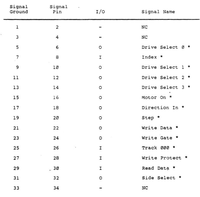
3.9 5.25" Floppy 34-pin Drive Control Connector
This floppy drive control connector S8 is a 34-pin vertical
header on 0.10-inch centers. Cabling should be flat ribbon or
twisted-pair cable, less than 20 feet long. The cable pinouts
Table 4 - Floppy Drive Control Connector Pin Description
Signal Signal
Ground Pin I/O Signal Name
1 2 NC
3 4 NC
5 6 0 Drive Select 0
*
7 8 I Index
*
9 10 0 Drive Select 1
*
11 12 0 Drive Select 2
*
13 14 0 Drive Select 3
*
15 16 0 Motor On
*
17 18 0 Direction In
*
19 20 0 Step
*
21 22 0 Write Data
*
23 24 0 Write Gate
*
25 26 I Track 000
*
27 28 I Write Protect
*
29 30 I Read Dati?-
*
31 32 0 Side Select
*
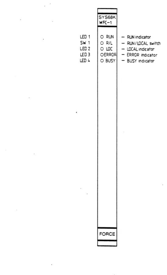
3.10 The Run/Local Switch
The switch on the front panel (see Fig.9) is used to set the
board into RUN or LOCAL mode. In the RUN mode normal access to
the on-board registers can be performed and the green RUN LED is
turned on.
No access to the on-board registers can be forced in LOCAL mode,
since" the board is isolated from the bus. This is indicated by
the red LOCAL LED on the front panel (see Fig. 9).
3.11 The LED Indicators
The front panel of the SYS68K/WFC-l contains two additional LEDs, BUSY LED and ERROR LED.
The BUSY LED is turned on if the board is busy and a command is
being executed.
The ERROR LED indicates that an error has occurred in the
execution of a command. The ERROR LED is turned off only when a
LED 1
SW' 1 LED 2
LED 3 LED 4
SYS68K WFC-1
o
RUNo
R/Lo
LOCOERRO~
o
BUSYFORCE
- RUN indicator - RUN I LOCAL switch - LOCAL indicator - ERROR indicator - BUSY indicator
3.12 Access Times
A Read/Write access to the SYS68K/WFC-l can be performed under
the following conditions :
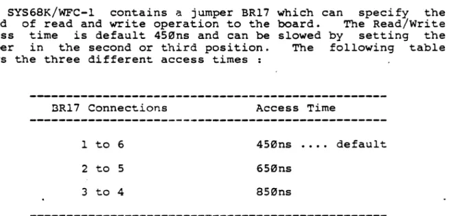
The SYS68K/WFC-l contains a jumper BR17
speed of read and write operation to the
-access time is default 450ns and can be
jumper in the second or third position.
shows the three different access times :
which can specify the
board. The Read/Write
slowed by setting the
The following table
BR17 Connections Access Time
1 to 6 450ns ..•• default
2 to 5 650ns
3 to 4 850ns
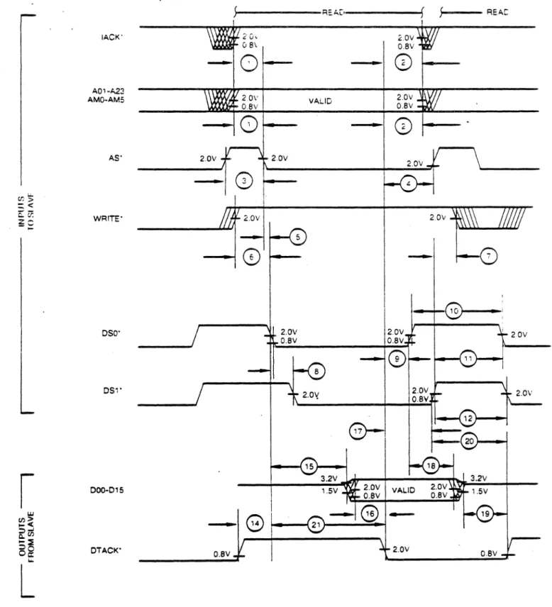
Fig. 10 shows the detailed Read Timing Diagram and Table 5 lists
the time values.
lACK'
A01-A22 AMO-AM5
AS"
Cf)~
=:<
ED: WRITE"
z~
- ' - '
..
050'
051'
I
000-0'5w
tn>
.. <
::l..J
c:..tn
"::E
::lO OTACK'
00::
1.0.
L
) REAL'
5
REAC2 (n, 2.0V
o S\
I
O.SV0 -
-
CD
20V VALID 2.0V
OSV O.SV
0
-
CD
2.0V 2.0V
2.0V
-0
-
1--+--8---2.0V O.SV
@
G
21-O.SV 2.0V
FIG. 10 DATA TANSFER BUS READ CYCLE (SLAVE TIMING)
Table 5.
-
Data Transfer Bus Read Time Values(Note A)
Number Parameter Min. Max. Notes
1 Axx and AHx valid and lACK* high
to AS'" low 113 E
2 DTACK* low to invalid address
IACK* low 13 D
3 AS'" High 313 E
4 DTACK* low to AS* high 0 D
5 AS* to DS"A"* skew -113 E
6 WRITE'" valid to DS"A"* low 113 E
7 DS"B"* high to invalid WRITE* 13 E
8 DS"A"* to DS"A"* skew 20 E
9 DTACK* low to DS"A"* high 13 D
113 DA"A"* high 30 E
11 DS"B"* high to DS"A"* low 313 E
12 DS"B"* high 30 E
13
14 DTACK*/BERR* high to DS"A"* low 13 D
15 DS"A"* low to Active data bus 0 C
16 Data valid to DTACK* low 13 B
17 DTACK* low to DS"B"* high 13 D
18 DS"A"* high to invalid data 0 C
19 Data bus released to DTACK*/BERR* 0 B
Notes:
A. All times given are in nanoseconds.
B. Th~ SYS68K/WFC-l guarantees this timing between two of its
outgoing signal transitions.
C. The SYS68K/WFC-l waits for the incoming signal edge from the
HASTER before changing the level of its outgoing signal.
D. This is
incoming signal.
a guarantee that the ~~STER will not change the
signal until the SYS68K/WFC-l changes its outgoing
E.· The SYS68K/vlFC-l is guaranteed this timing between t-wo of
w
rJl>
-<
::1_
=-rJl
~:)
-lACK'
A01 ·A23 AMO·AMS
AS'
WRITE'
DOO·015
OSO'
OS1'
DTACK'
BERR'
Wf:.<ITE
2.011 2.0V
OSV osv
0
•0
20V VALID 2.0V
O.SV o.sv
0
2.0V
Table 6. - Data Transfer B~s Write Time Values
(Note A)
Number Parameter Min. Max. Notes
1 Axx And AMx valid and IACK* high
to AS* low 10 D
2 DTACK* low to invalid address or \
IACK* low 0 C
3 AS* high 30 D
4 DTACK* low to AS* high 0 C
5 AS* to DS"A" skew -10 D
6 WRITE* valid to DS"A"* low 10 D
7 DS"B"* high to invalid WRITE * 0 D
8 Data valid to DS"A"*low 10 D
9 DTACK* low to invalid data 0 C
10 DS" A" * to DS"B"* skew 20 D
11 DTACK*/BERR* low to DS"A"* high 0 C
12 DS" A "* high 30 D
13 DS"B"* high to DS "A"* low 30 D
14 DS"B"* high 30 D
15 DS"A"* low to-DTACK* low 230 250 B
16 DTACK*/BERR* low to DS"B"* high 0 C
17 DS"B"* high to DTACK*/BERR*"high 0 B
Notes:
A. All times given are in nanoseconds.
B. The SYS68K/WFC-l must wait for the incoming signal edge from
the MASTER before changing the level of its outgoing
signal.
c.
This is a guarantee that the Bus MASTER will not change theincoming signal until the SYS68K/WFC-l changes its outgoing
signal.
D. The SYS68K/WFC-l is guaranteed this timing between two of
its incoming signal transitions.
E. The SYS68K/WFC-l guarantees this timing between two of its
4.0 SYS68K/WFC-1 Register Set
4.1 Register Set Basics
The SYS68K/~~C-l performs all disk functions through a set of
registers . . The registers are loaded with parameters such as
sector number, cylinder number, etc., prior to issuing a command.
Individual registers are selected via AI-A3 for both types of
drives. There are only Read-Only/Write-Only Registers and a FIFO
Buffer for data.
4.2 SYS68K/WFC-l Address Map
Table 7. shows the available registers and the
SYS68K/WFC-l Address Map.
default
Address Default Read Register vlri te Register
B01000
B01001 Data Register
B01002
B01003 Error Register
B0l005 Sector Count
B01007 Sector Number
B01009 Cylinder Low, <
B0100B Cylinder High**
B0100D Size/Drive/Head
B0100F Status Register
Complete Interrupt Vector Register Data Register
Data Req Interrupt Vector Register Write Precomp*
Sector Count
Sector Number
Cylinder Low
Cylinder High**
Size/Drive/Head
Command Register
---*
**
not used on floppies
4.3 Data Register
This register is the user's window to the on-board full sector
buffer. It contains the next byte of data to b~ written to or
read from the internal sector buffer. When the DRQ (Data
Request) bit is asserted, the second buffer contains data ~o be
read during a Type II command, or is awaiting data to be written
during a Type III command. If the SYS68K/WFC-l is interfaced
using programmed I/O, data transfers to this register can be
implemented using programmed block moves. This register may not
be read from or written to except in the context of a valid
command.
4.4 Error Register
This register contains specific fault information pertaining to
the last command executed. This register is only valid if the
error bit in the status register is set. The error register is
read only. Table 8 shoes the error register bits.
Table 8 - Error Register Bits
Error Register
7 Bad Block Detect
6 Uncorrectable Error
5
4 ID not found
3
2 Aborted Command
1 TR0"" Error
Error Register Bits Description
DAM NOT FOUND
TR000 ERROR
ABORTED COMfvlAND
ID NOT FOUND
UNCORRECTABLE ERROR
BAD BLOCK DETECT
will be set during a read sector command, if,
after successfully identifying the ID field,
the data address mafk has not been detected
within 16 bytes of ID field.
Will be set during a restore command if the
track 000 line has not been asserted by the
drive. after all stepping pulses have been
issued. The Winchesters are issued a maximum
of 1023 stepping pulses and the floppies a
maximum of 256 stepping pulses.
Indicates that a valid command has been
received that cannot be executed based on
status information from the drive, i.e. drive
not ready, seek complete not asserted, or
write fault. Interrogation of the status
register by the host may be performed to
determine the cause of this failure.
When set, this bit indicates that an ID field containing a specified cylinder, head, sector
number or sector size has not been found
after all the retries have been executed.
Indicates that an
-encountered in a
sector command
uncorrectable.
ECC or CRC error has
data field during a
and the error
been read was
Indicates that a bad block mark has been
detected in the specified ID field. If the
command issued was a write sector command,
write gate may be pulsed but the sector will
not be written If generated from a read
sector command, the data field will not be
read. Note that bad block may not be
4.4.1 Diagnostic Errors
On power-up, or when specifically commanded tcr, the SYS68K/WFC-l
will run a series of internal diagnostic tests. When an error is
encountered, the diagnostic routine is terminated. A binary
error code is set in the error register without the error bit of
the status register being set. ~e diagnostic routines are
exercised in the following order :
Error Code Major Functional Fa~lure
5 WD1015 error
4 WD1014 or bus error
3 Sector buffer'error
2 WD1010 error
1 WD2797 error
0 Pass-board is functional
4.5 Write precompensation Register
The write precompensation register holds the cylinder number
where the RWC line will be asserted and write compensation logic
is to be turned on. This write-only register is loaded with the
cylinder number divided by 4 to achieve a range of 1024
cylinders. For example, if write precompensation is desired for
cylinder 128 (80 Hex) and higher, this register must be loaded
with 32 (20 Hex). The writer precompensation delay is fixed at
12 nanoseconds from nominal.
This register is not used for floppy disk drives.
write precompemsation is contained in WD2797.
4.6 Sector Count
Floppy disk
The sector count register is used in read sector, write sector,
4.7 Sector Number
This register is loaded with the desired sector number prior to a
read or write command. The sector number register may be read or
written to by the host.
4.8 Cylinder Number
These two registers form the cylinder number where the head is to
be positioned on a seek, read, or write command. The two least
significant bits of the cylider high register form the most
significant bits if the cylider number as illustrated below:
Cylinder High Cylinder Low
Register bits
Cylinder bits
7 6 5 4 3 2 1 3 7 6 5 4 3 2 1 3
9 8 7 6 5 4 3 2 1 0
When bit 0 of the cylinder high register (bit
register) is set to a 1 during floppy operation, be used in 96 tpi disk drives for all commands. set to 0, only 96 tpi disks can be used.
-4.9 SDa Register
8 of cylinder
48 tpi disks can When this bit is
This register contains the ECC/CRC sector size, drive select, and
head select bits. The SDa register is a Read/Write Register
organized as shown in Table 9.
The SDa register is used to select either the Winchester or the
floppy disk drives as implied by bits 3 and 4 shown in Table 9.
If either bit is set to zero, then one of the hard disks is
selected, and bits 3, 1, and 2 are used to select one of eight
heads.
When bits 3 and 4 are both set to 1, then a floppy disk will be
selected. Bits 3, 1, and 2 are used to select one of four drives
with side select 3 or 1 as ~hown.
lihenever different drives are to be accessed, the SDH register
must be updated by the host prior to a command being issued.
The ECC/CRC bit is only supported for the Winchester Disk
Controller, therefore the host must be set to SDH bit 7 - 3 for
all floppy commands. If SDH bit 7 is set to 1 by a Winchester
operation, then the Error Correction Mode is supported. If this
bit is cleared (-3), then a CRC generation and verification for
Table 9. - Size Drive Head Register
Bit
Function
I
I
,
,
_ ---.;.7_
I
6 5 4 3 ' 2 1-,-~-~-
o
,
-,
CRC/' Sec
ECC I
,
Size,
Drive , Select ,
,
I
Head/ Drive Select
SDH Bits 6 & 5
,
Bit , Bit Sector Size
6 , 5
,
----,---
---,_._---
---Bit 2 0 (3 0 0 1 1 1 1o
,
0o
,
11 , 0
1 , 1
I
256 Bytes 512 Bytes 1024 Bytes 128 Bytes
SDH Bits 2, 1 & 0 Hard Disk
I
Bit 1 Bit Head Selected
1 1 0 Hard Disk
1
---I
0 I {3 Head 0
0
I
1 Head 11
I
0 Head 21
I
1 Head 30 1 (3 Head 4
0
I
1 Head 51 1 0 Head 6
1 1 1 Head 7
Table 9. Size Drive Head Register
SDH Bits 4 & 3
Bit Bit Drive Selected
4 3 (decoded & latched)
(3 (3 Drive Sel 1
(3 I Drive Sel 2
I (3 Drive Sel 3
1 1 Floppy Dr Sel
::;DH Bits 2, I & (3 Floppy Disk
---I
1Bit Bit Biz I Floppy Drive & 1
2 I 0
I
Head Select 1I 1
--I
10 0 0 1 FDI
-
HS0 10 0 I
I
FDI-
HSI 10 I 0
I
FD2-
HS0 I(3 1 1
I
FD2-
HSl 11 0 0 1 FD3
-
HS(3I
1 (3 I 1 FD3
-
HSII
I 1 0 1 FD4
-
HSe 1I 1 I 1 FD4
-
HSl 11 1
---4.10 Status Register
After execution of a command, the status register is loaded with
status information pertaining to the command executed. The host
must read this register to ascertain successful execution of the
command. The status register is a read-only register: i t cannot
be written to by the host. If the BUSY bit is set, no other bits
in this register are valid.
Status register bits are shown as follows :
ERROR
CORRECTED DATA
Bit Status Register
7 Busy
6 Drive Ready
5 Write Fault
4 Seek Complete
3 Data Request
2 Corrected Data
1 Not used
0 Error
When set, indicates that one or more bits are set in
the error register. It provides an efficient means
of checking for an error condition by the host.
This bit is reset on receipt of a new command.
This bit indicates that an error correction has been
successfully completed on the data field just read
from the Winchester disk. For multiple mode
DATA REQUEST When set, it indicates that the sector buffer is ready to accept data or contains data to be read by
the host. The data request bit is reset when the
sector buffer has been fully read ·or written.
Normally, the host need not consult this bit to
determine if a byte should be transferred.
SEEK COMPLETE Indicates the condition of the seek complete line
on the selected Winchester drive. For floppy
drives, this line is asserted when the SOH register
is relo~ded.
WRITE FAULT/ ilRITE PROTECT
READY
BUSY
Indicates the condition of the write fault line on
a selected Winchester drive. The SYS6BK/WFC-l will
not execute any command if this bit is set. If a
write-protected disk is sensed in a selected floppy drive during a write operation, the write fault bit
will be set. The command will then be aborted and
no writing will take place.
Indicates condition of ready line on drive.
SYS68K/WFC-l will not execute any commands unless
the ready bit is set. Normally, this line is
asserted for floppy drives when the SOH register
selects any floppy drive. A user available jumper
BR3 option can be implemented if the READY line is
available from the floppy drive.
After issuing a command, or initialising
SYS68K/WFC-l internal diagnostics, this bit will be
set, indicating that the SYS68K/WFC-l is busy
executing a command. No other bits or registers
are valid when this bit is set.
4.11 Command Register
All commands are loaded into this register after all other
registers have been set.
The command register is a Write Only Register.
4.12 Interrupt Vector Registers
The SYS68K/WFC-l controller board contains two write only
interrupt vector registers. The first interrupt vector register
is for the complete interrupr and the second one for the data
request interrupt. The registers are free programmable and the
5.0 Commands
5.1 General
The SYS6BK/WFC-l executes six, easy-to-use, macro. commands. Most
commands feature automatic "implied" seek, which means the host
system need not tell the SYS6BK/WFC-l where the R/W heads of each
drive are nor when to move them. The controller automatically
performs all retries on error encounters, including data BCC
Errors. If the R/W head mis-positions, the SYS6BK/WFC-l will
automatically perform a restore and a re-seek. If the error is
completely unrecoverable, the SYS6BK/WFC-l will simulate a normal completion to simplify the host's software.
The commands executed by the SYS6BK/WFC-l are mapped to the
commands supported by the two disk controllers. The format of
the SYS6BK/WFC-l commands is the same as that of. the WD1010
commands. The on-board WD101S buffer manager translates this
format for the WD2797, transparent to the user. Error correction
is only supported for the Winchester disk controller, therefore,
the host must set SDH bit 7 = 0 for all the commands when a
floppy disk is selected.
Commands are executed by loading the command byte into the
command register while the controller is not busy. The host must
observe the following simple protocol:
The registers must be loaded prior to issuing a command.
Only parameters that change from the previous command need
be entered.
For any write/format operations, the sector buffer must be
filled with the appropriate data before the command can be executed by the SYS6BK/WFC-l.
No command will execute if the seek complete or ready lines are"
false, or the write fault line is true. Normally it is not
necessary to poll these signals before issuing a command. If a
command is received, that is not defined in Table 10. , undefined results will occur.
5.2 SYS6BK/WFC-l Command Summary
Table 10 - Command Types
Bits
Type Command 7 6 5 4 3 2 1 0
I Test 1 0 0 1 0 0 0 0
I Restore
"
0 0 1 r3 r2 r1 r0I Seek 0 1 1 1 r3 r2 rl r0
I I Read Sector 0 0 1 0 D M 0 0
I I I Write Sector 0 0 1 1 0 M 0 0
I I I Format Track 0 1 0 1 0 0 0 0
M = Multiple Sector M = 0 : Single Sector
D = Read Interrupt D =
"
: ProgrammedIlo
Moder.1 = 1 Multiple Sector
D = 1 DMA Mode
Table II. r3-r0 Stepping Rate
r3-r0 vlinchester Disk Drives Floppy Disk Drives
0000 approx. 35 us approx. 15 us
0001 0.5 ms 1.0 ms
0010 1.0 ms 2.0 ms
0011 1.5 IDS 3.0 ms
0100 2.0 ms 4.0 ms
0101 2.5 ms 5.0 ms
0110 3.0 ms 6.0 ms
0111 3.5 ms 8.0 ms
1000 4.0 ms 10 ms
J.001 4.5 ms 12 ms
1010 5.0 ms 14 ms
1011· 5.5 ms 16 ms
1100 6.0 ms 18 ms
1101 6.5 ms 20 ms
1110 7.0 ms 25 ms
5.3 Type I Commands
Type I commands do not effect transfer of data between the host
and the SYS68K/WFC-l, but merely position the R/W heads of the
selected drive or run diagnostics. The restore ~nd seek commands
have explicit stepping rate fields. The lower four bits of these
commands form the stepping rate for the drives.
5.3.1 Test Command
Bit code: 1 1
The test command is used to run internal diagnostics for checking
SYS68K/WFC-l board function. It is mainly employed to isolate
faults in the board logic. This command is always executed on a
RESET. Any faults are reported as e~ror codes.
5.3.2 Restore
Bit code: 0 1 R3 R2 Rl R0
The restore command is used to calibrate the position of the R/W
head on each drive by stepping the head outward until the TR000
line goes true. Upon receipt of the restore command, the BUSY
bit in the status register is set. Cylinder High and cylinder
Low Registers are cleared. For Winchester operation, the actual
stepping rate is determined by the Seek Complete period. For
floppy operation, a minimum stepping pulse of 8 msec. is used.
However, the stepping rate field specified by the host is saved
internally for use in all future implied seeks. The state of
seek complete, ready and write fault are sampled, and if an error
condition exists, the aborted command bit in the error register
is set, the error bit in the status register is set, an interrupt is generated, and the BUSY bit is cleared.
Regardless of errors encountered, the internal head position
register for the selected drive is cleared. The TR000 line is
sampled. If TR000 is true, an interrupt is generated and the
BUSY bit is reset. If TR000 is not true, stepping pulses at a
rate determined by the stepping rate field are issued until the
TR000 line is activated. When TR000 is activated, the busy bit
is reset and interrupt is issued. If ~he TR000 line is not
activated within 1024 stepping pulses, the TR000 error bit in the
error register and the error bit in the status register are set,
5.3.3 Seek
Bit code: 0 1 1 1 R3 R2 Rl R0
The seek command positions the R/W head at a certain cylinder.
It is primarily used to start two or more concurrent seeks on
drives that support buffered stepping. Note that the" seek
complete line is not sampled after the seek command so that
multiple seek operations may be started using drives with
buffered seek capability_
5.4 Type II Commands
Type II commands characteristically transfer blocks of data from
the SYS68K/WFC-l buffer to the host. This type of command has an
implicit stepping rate as set by the last restore or seek
command.
5.4.1 Read Sector
Bit code: 0
o
1o
D Mo
o
The read sector command is used to enable the host computer to
read a sector of data from the disk. If ECC is enabled, ECC
bytes are recomputed by the SYS68K/WFC-l. After the buffer is
full, the recorded ECC bytes are compared to the recomputed check
bytes to generate the syndrome bytes. If the syndrome is
non-zero, errors have occurred. Error correction is invoked by the
WD10l5 if two consecutive syndromes match, otherwise a maximum of
8 retries is attempted by the WD10l5. If the data is
correctable, the WDl015 makes the correction and passes the data
in the buffer to the host. If, -after eight retries, the
syndromes do not match, the SYS68K/\irC-I sends an error status to
the host along with the status from the WD1010. Multiple sector
read commands are modified to single secto.r commands and are
issued a multiple number of times. The status and error
registers are updated for every block of data transferred.
During a floppy read sector operation only eRC is used with the
data fields. If a eRe error occurs in the data field, the WD1015
buffer manager attempts a maximum of 8 retries and reports the
error only if it persists. Regardless of the drive accessed
5.4.1.1 DMA Read
D = DMA Read Mode
I
0 = Programmed I/O Mode I .
1 = DMA Mode I
I
The DMA bit is used to position INTRO in relation to DROs during
the read sector command. If the DMA bit is reset (D=0), the
interrupt will occur along with the DRO. This allows the
programmed I/O host to intervene and transfer the data from the
sector buffer. For programmed I/O, multiple transfer is not
permitted (M=0). If the DMA bit is set (D=l), then the interrupt
will occur only after the system DMA controller has transferred
the entire buffer· of data. This mode is always used with
multiple sector transfers.
5.4.1.2. Normal Completiop
A normal completion occurs when the SYS68K/WFC-l encounters no
errors. The BUSY bit is reset.· The status of the DMA bit in the
command byte is examined. If this bit is reset (D=0; programmed
I/O mode), an interrupt is issued at this time. DRO is set until
all bytes of data have been read from the buffer. (Note: It is
recommended that programmed I/O transfers should take place as a
block move without consulting the DRQ bit in the Status
Register). After all the data have been moved from the buffer,
the DMA bit in the command byte is consulted again. If this bit
is set (D=l; DMA mode) then an interrupt will be issued.
5.5 Type III Commands
This type of command is characterized by a transfer of a block of
data from the host to the SYS68K/WFC-l buffer. These commands
have implicit stepping rates as set by the last restore or seek
command.
The command will not be executed by the SYS68K/WFC-l controller
5.5.1 Write Sector
Bit code: 0
o
1 1 Mo
The Write Sector command is used to write a sector of data from
the host computer to the disk. Upon receipt of the write
command, the controller sets ORO until the entire sector length
of data has been written into the buffer. (Note: It is
recommended that programmed I/O transfers should take place as a
block move without consulting the ORO bit in the Status
Register.)
5.5.2 Format Track
The format command is used for initializing the 10 and data
fields on a particular disk. Upon receipt of the format command,
the controller sets the ORO for the interleave table to be
written to the buffer. In all cases, the number' of bytes
transferred to the buffer must correspond to the current sector
size.
When the buffer has been completely filled, the specified number
of sectors are written and the DRO is reset. The data field is
written with 00 for the hard disks and E5 (hex) for the floppies.
ECC or CRC byte~ ~re automatically computed and written.
Once the index is found, a number of ID and data fields are
written to the disk. As each sector is written, the sector count
register is decremented and consequently must be updated before
6.0 Programming
6.1 General
Users will find programming the SYS6BK/WFC-l relatively simple as
a substantial amount of intelligence formerly required by host
computers has been incorporated into the SYS6BK/WFC-l board.
The SYS68K/WFC-l performs all needed retries, 'even on head
positioning errors. If there is an error in the data field, the
SYS6BK/WFC-l will attempt to correct it.
Most commands feature automatic "implied" seek, which means that
seek commands need not be issued to perform basic read/write
functions. The SYS6BK/WFC-l keeps track of the head position up
to eight read/write head assemblies, eliminating the need for the host system to maintain track tables.
All transfers to and from disk are through an on-board sector
buffer. This means that data transfers are fully interruptable
and can take place at any speed that is convenient to the system
designer. In the event of an unrecoverable error, the
SYS68K/WFC-l simulates a normal completion so that special error
recovery software is not needed.
6.2 Setting Register Set
Before any of the six macro commands may be executed, a set of
parameter registers must be set up. For most commands, this
informs the controller board of the exact location on the disk
where the data involved in the transfer is located or will be
placed. For a normal read or write sector operation, the sector
number, the size/drive/head, the cylinder number, and the command registers (usually in that order) will be written.
Note that although most of these registers are readable as well
as writeable, they normally are not read from. Read capability
for them is provided, however, so that error-reporting routines
can determine physically where an error occurred without
recalculating the sector, head, and cylinder parameters.
since all parameters can be recalled by the SYS68K/WFC-l, i t is
recommended that task file parameters be stored in the
SYS68K/WFC-l as they are calculated. This will save the
6.2.1 Cylinders and Tracks
Since most hard-disk drives contain more than one head per
positioner, it is more efficient to step the R/W head assemblies
of most disk drives by cylinders, not tracks. In other words, the disk drive software should be designed to read"or write all data
that are directly accessible by all the heads on a position
before stepping to a new cylinder.
The following table shows an example
---1 1 1
1 Logical 1 1
Physical 1 Head 1 Physical Physical 1
Cylinder 1 Number 1 Head Side Platter I
1 1 1
- - - I
--·---1
-I
25 1 3 1 Top B
1 1
26 1 0 I Bottom A
1 1
26 1 1 1 Top. A
1 1
26
I
2 1 Bottom· BI
I
26 1 3
I
Top B1 1
27
I
0I
Bottom AI
I
---6.3 Type I Command Programming
Test, Restore and seek are Type I commands that position the R/W
heads of the selected drive and set the implied stepping-rate
register. No data is transferred to or from the data register.
To execute a Type I command, the system software must perform the following functions in the order shown:
1. Set up register set and issue command with stepping rate.
2. Wait for interrupt or for BUSY bit in status register to be
reset.