Abstract — At the present time there are many identification methods. This is due to the variety of identification methods, their different purposes and the limitations imposed on the described process. In this article the research results of the active identification method of a plant in a closed loop control on the example of a flame reactor for the production of uranium hexafluoride. The obtained identification results prove the applicability of the developed identification method of industrial plants under the conditions of uncontrolled disturbances.
Index Terms— Closed-loop identification, PID-controller, Control system.
I. INTRODUCTION
igh-quality work of automatic control systems is the basis of industrial security, durability and accessibility of economic indicators that provided by automated control systems of technological processes generally. However, often a change of physical and mechanical characteristics of raw materials, variable load of production and various switching change characteristics of a plant that leads to the need to reconfiguration of control systems. The problem of providing high dynamic accuracy of the local automatic control systems for plants with variable parameters can be solved by adapting controller setting of the automatic control systems to change plant characteristics.
Therefore the development of effective and reliable methods for automatic tune of the automatic control system is very important and actual task. A typical approach for
Manuscript received December 7, 2015; revised February 28, 2016. N. S. Krinitsyn is with the National Research Tomsk Polytechnic University, Institute of Physics and Technology, Department of Electronics and Automation of Nuclear Plants, Russia, Tomsk, Lenina St 30, 634050 (corresponding author to provide phone: +7-960-975-24-32; e-mail: [email protected]).
A. D. Uvarova is with the National Research Tomsk Polytechnic University, Institute of Physics and Technology, Department of Electronics and Automation of Nuclear Plants, Russia, Tomsk, Lenina St 30, 634050 (e-mail: [email protected]).
V. F. Dyadik is with the National Research Tomsk Polytechnic University, Institute of Physics and Technology, Department of Electronics and Automation of Nuclear Plants, Russia, Tomsk, Lenina St 30, 634050 (e-mail:[email protected]).
A. G. Goryunov is with the National Research Tomsk Polytechnic University, Institute of Physics and Technology, Department of Electronics and Automation of Nuclear Plants, Russia, Tomsk, Lenina St 30, 634050 (e-mail: [email protected]).
I. S. Nadezhdin is with the National Research Tomsk Polytechnic University, Institute of Physics and Technology, Department of Electronics and Automation of Nuclear Plants, Russia, Tomsk, Lenina St 30, 634050 (e-mail: [email protected]).
providing automatic tune of the automatic control system involves the solution of two important tasks: identification of the plant and the calculation of controller setting.
At the present time the identification theory of systems have achieved a high stage of completion. Good results have been achieved in the field of identification in open-loop control systems. But in some cases, when solving identification problems, to break the feedback is impossible, because it is a necessary part of the system or for security reasons, when open-loop control systems is unstable. Also often there is no way to break the feedback in the case, when chances are high that procedural norm for the technological process will be broken. Moreover, closed-loop data often more accurately reflect the real situation, in comparison with the data, which were obtained by breaking the feedback.
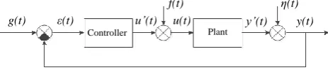
The most control systems in the chemical industry have the structure, presented in figure 1. In capacity as a controller uses the PID-controller. The controller parameters are calculated by specific methods to ensure the highest achievable quality control and robustness.
g(t) ε(t) u’(t) u(t)
f(t) η(t)
y’(t) y(t)
Controller Plant
[image:1.595.308.540.443.493.2]g(t) – reference signal, ε(t) – error signal, u`(t) – control signal, calculated by the controller, f(t) – disturbance, u(t) – input signal of the plant, y`(t) – true output signal of the plant, η(t) – noise, y(t) – observed output signal of the plant
Figure 1 – The structure of the automatic control system
The identification problem in a closed-loop system consists in finding model parameters of the plant on basis of data obtained by the measurement and processing of various system coordinates: g(t), ε(t), u`(t), u(t), y(t). Depending on the problem description identification methods of the plant in a closed loop control can be divided into the following main groups [1]:
1. Direct approach. This approach consists in the fact that the identification of the plant is performed based on the measured input u(t) and output y(t) signals [2, 3]. The main advantage of a direct approach of identification is the lack of necessity of receiving information about control system and acting on the system external disturbances.
2. Indirect approach. It consists in the identification of the plant on basis of data specifying change of the reference signal g(t) and output signal y(t). In this approach is assumed that structure of the controller must be known [4, 5, 6, 7, 8, 9, 10]. The indirect approach consists of two stages:
• Identification of closed-loop system from reference
Plant Identification in the Closed-loop
Control System
Nikolay S. Krinitsyn, Anastasiya D. Uvarova, Valeriy F. Dyadik, Aleksey G. Goryunov,
Igor S. Nadezhdin
signal g(t) to output signal y(t);
• Definition of plant parameters by separation from the known model of a closed-loop system plant model.
Static and dynamic characteristics of chemical processes are sensitive to a large number of factors. Some factors measured, and some are not. Therefore there is a requirement to ensure the system robustness. In paper [11] is proved that for the synthesis of the PID-controller of robust control system sufficiently describe the plant with self-alignment by the differential equation (1).
( )
( ) K ( ), dy t
T y t u t
dt (1)
where К is gain; Т is time constant, s; τ is delay time, s. Under the conditions the action of uncontrolled external disturbances passive identification using the methods, presented in [2, 3, 4, 5, 6, 7, 8, 9, 10], gives low accuracy. The presence of feedback leads to the fact that the signals
u(t) and y(t) are related not only the plant operator, but
controller operators and disturbance channels. This dependence may lead to unidentifiability of the plant.
Thus, we can conclude that the direct approach of closed-loop identification is preferred. In this case, should comply with the following conditions:
to apply the test action at the plant input that involves (provokes) an obviously more active response of the plant versus response of the plant to typical disturbances f(t) and noise η(t);
at identification it is necessary to use the signals measured on the input u(t) and output y(t) of the plant;
to choose characteristics of test action taking into account requirements of minimization of its influence on the course of the controllable technological process.
II. THEORETICAL PART
In this article we will consider efficiency of the offered identification method on the example of control system of the flame reactor [12]. The plant in this system is described by the differential equation (2).
3 2
FR
3 2
( ) ( ) ( )
5250d y t 1025d y t 60dy t y t( ) K u t( 100).
dt
dt dt
(2)
The controller parameters of the control system calculated by the method of optimal module [13], provided approximation of the original plant model (1) with parameters K = 1; T = 42 s; τ = 121 s. In practice, for the open-loop identification process their response to a typical action. These include a step and pulse changes the controlling coordinates u(t). Consider the application consequences of these actions in the closed loop control.
Transient process of the output signal y(t) of the closed-loop automatic control system to step and pulse changes of the control signal u’(t) is presented in figure 2.
As can be seen from figure 2, with the same amplitude (Δu’(t) = 22 %) influence of the pulse action is significantly lower than the step action. Therefore, identification of the
plant in a closed-loop system under the assumed restrictions should be feeding pulse action to the plant input.
0 5 10 15 20 25 30
0 200 400 600
y
(t)
(
%)
Time (s) a
[image:2.595.312.537.76.215.2]b
Figure 2 – Transient response of the plant y(t) in a closed control loop for step (a) and pulse (b) change of control action u(t)
In reference [14] proved that on response of the open-loop automatic control system (figure 3) to pulse change of the control signal, using the method of planimetering, can accurately determine the model parameters (1) describing the behavior of the plant. Calculation of parameters of the plant according to the method of planimetering encouraged to produce by the equations (3).
0 5 10 15 20 25
0 100 200 300
a
b
Sin
Sout
Δymax
x
(t)
,
y
(t)
(
%)
Time (s)
S1
S2
τ'
[image:2.595.311.536.333.469.2]tu
Figure 3 – The response of the plant to pulse change of the input signal (a): out
S - area, bounded by the output coordinate of the plant y(t); Sin- area, bounded by the input coordinate u(t);t’- time point corresponding to the equality of the areas S1 andS2; ymax - maximum deviation of the output coordinate of the plant y(t) from the initial value
out out
in max
; ; .
2 u
S S t
К Т
S y
(3)
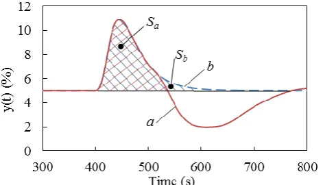
Comparing the response of the closed-loop and open-loop automatic control system (figure 4) on the pulse action of the same size (figure 4) can be noted the proximity of the areas S1 andS2.
Figure 4 – The response of the closed-loop (a) and open-loop (b) automatic control system to the pulse change of the control action: Sa is area, bounded
[image:2.595.310.546.619.754.2]This fact gives a basis to explore the possibility of using the method of planimetering to determine the reference values of the plant model parameters (1) in a closed loop control.
Increasing accuracy of description of the plant model (1) can be achieved by the application of optimization methods of functional (4).
21
, ,
m
j j
j
y f q x
(4) [image:3.595.311.544.52.192.2] [image:3.595.309.546.545.687.2] [image:3.595.53.285.567.701.2]where yj – measured output signal of the plant on the j-th step; f q x
, j
– response of plant model with parameters[k, T, ]T
q
on the input signal xj.In this article used the Levenberg-Marquardt method [15, 16] due to the fact that it is the most stable among analogues. This method allows to achieve a minimization of the functional (4) due to the consecutive correction values of the model parameters by equation (5).
1
) , (
T T T
j
q J J diag J J J g f q x
(5)
To calculate the components of equation (5), continuous plant model (1) is represented the equivalent discrete model (6):
1 1 2
0 1 2 1 2 3
, , ( , , )
( ) (
( ) ( ( )
),
) ( )
j j j j
j d j d j d j d
q x q x q x q x
x x
f
x x
f f f
(6)
where 1T; 0 (1 1c); 1 ( 1c); ;
e K k d c
t
- quantization interval of input and output signals;
d
- whole amounttprevailing in the τ intervals t; c - fractional interval.III. RESULTS OF EXPERIMENTAL RESEARCH
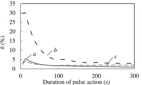
The efficiency of the developed identification method is tested in two stages. The first stage involved the definition of reference values of the plant model parameters (1) according to the method of planimetering (3). The second stage contained an optimization of the reference plant model parameters according to the Levenberg-Marquardt method. The results of the first and second stages of the identification of the plant at different durations of pulse action are presented in figures 5 and 6.
0 50 100 150 200 250 300
0 100 200 300
δ
(%)
Duration of pulse action (s) a b
c
Figure 5 – The dependence of relative errors of the model parameters of the plant on the first stage of identification from the duration of pulse action: a
– gain (K); b – time constant (T); с – delay time (τ)
0 5 10 15 20 25 30 35
0 100 200 300
δ
(%)
Duration of pulse action (s)
a b c
Figure 6 – The dependence of relative errors of the model parameters of the plant on the second stage of identification from the duration of pulse action: a – gain (K); b – time constant (T); с – delay time (τ)
The relative error, illustrated in Figures 4 and 5, is numerically evaluates the compliance of the results of identification parameters: K = 1; T = 42.1 s; τ = 120.9 s.
The presented data show that when using the method of planimetering at small durations of pulse action gain and delay time of the plant model determined with sufficient accuracy, but it does not ensure the required accuracy of the time constant. After the second stage of identification the accuracy of determination of all model parameters increases significantly (figure 6).
The main purpose of identification is drawing up a model simulating the plant behavior in conditions close to the operating point. To check the degree of achievement of this requirement were calculated according to equation (7) values of the adjusted mean square deviations.
21
(t ) ,
1 100 n j j j y
y f q x
n l
(7)where n is the number of discretization steps in the observation interval; l is change range of the output coordinates y(t);
The results of calculation of the parameteryfor the first and second stage of identification is presented in figure 7. 0 2 4 6 8 10 12
0 100 200 300
Duration of pulse action (s) δy
(%)
a
b
Figure 7 - The adjusted mean square deviations (t )y j from f q x
, j
: a -at the first stage of identification; b - at the second stage of identification The accuracy of behavior description of the original plant in a closed loop y(t) by models made on the first and second stages according to figure 7 was less than 11 % and 3% respectively.
hexafluoride. As a result of performed analysis of the flame reactor control system were selected characteristics of a pulse action. The amplitude of pulse action is taken to be 10% of the nominal value, the duration is 40 seconds (from the deviation of the output y (t) is not more than 5 %). The result of experimental research in industries served as the input u(t) and output y(t) coordinate of the flame reactor, presented in figures 8 and 9.
74 76 78 80 82 84 86 88
0 200 400 600 800
u
(t)
(
%)
[image:4.595.54.283.330.466.2]Time (s)
Figure 8 – Frequency of rotation of the download screw uranium oxides in the flame reactor in a closed loop control
8 9 10 11 12 13
0 200 400 600 800
y
(t)
(
%)
Time (s) a
b c
Figure 9 – Concentration of fluorine in the flame reactor output: a is the production data; b is the data received from the model (1) with parameters defined at the first stage of identification; c is the data obtained from the model (1) with parameters defined at the second stage of identification
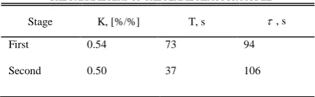
The parameters of the flame reactor model, calculated for two stages of identification, are presented in Table I.
The error description of the original data by model (1) with the parameters, found on the first and second stages of identification (Table I), estimated by value of the adjusted mean square deviations, was 7.2% and 4.4%. The achieved accuracy of identification is sufficient to use the found parameters for the model (1), describing the flame reactor for the synthesis of control systems.
IV. DISCUSSION OF THE RESULTS
The problem of identification of the plant in the closed loop is important part of the design process of control systems. This article proposes the identification method,
based on the analysis of response of the closed-loop control system on the test pulse action, supplied to the input of the research plant. The choice of pulse action is justified by the requirement for minimum intervention in the technological process. The amplitude of pulse action is limited to the operation features of actuation mechanisms and regulating units. The duration of pulse action is selected based on restrictions imposed on the maximum allowable deviation of the output coordinates of the system.
The aim of identification is definition the parameters (K, T, τ) of model, describing the plant with self-alignment by the first-order differential equations with delay. The identification carried out in two stages. At the first stage the reference values of the required model parameters determined by method of planimetering. At the second stage of identification is performed the specification of parameters of plant model. For that end the functional minimizes by Levenberg-Marquardt method (4). The conducted researches proved that the model required parameters are determined with an error of less than 3%. The achieved accuracy of the description of the plant for the synthesis of single-loop control systems is sufficient.
The proposed method was tested in the identification of flame reactor for the production of uranium hexafluoride. The identification results were used in the parametric synthesis of control systems of this device.
V. CONCLUSION
This article is devoted to the development and research of the active identification algorithm of plant in a closed loop control. Obtained results during the research prove the applicability of the proposed algorithm for identification of the plant by measuring its input and output coordinates. The paper presents the identification results of the flame reactor of fluorination production of uranium hexafluoride.
REFERENCES
[1] U. Forssel, L. Liying. Closed-loop identification revisited. Automatica, 1999.
[2] V. A. Krivonosov, Y. V. Durneva. Identifikaciya ob"ekta po rezul'tatam ego normal'noj ehkspluatacii v zamknutom konture upravleniya. Vestnik Voronezhskogo gosudarstvennogo tekhnicheskogo universiteta, vol. 5, no. 1, pp. 44-47, 2009.
[3] C. T. Chou, M. Verhaegen. Closed-loop identification using canonical correlation analysis. European Control Conference, ECC 1999 - Conference Proceedings, 2015.
[4] O. A. Lipa, D. A. Lipa, Y. A. Sidnik, V. V. Soldatov. Aktivnaya identifikaciya zamknutyh sistem adaptivnogo upravleniya. Vestnik Rossijskogo gosudarstvennogo agrarnogo zaochnogo universiteta, vol. 14, no. 19, pp. 96-101, 2013.
[5] J. Bendtsen, K. Trangbaek. Closed-loop identification for control of linear parameter varying systems. Asian Journal of Control, vol. 16, no. 1, pp. 40-49, 2014.
[6] Z. G. Salihov, A.L. Rutkovsky, D.N. Djunova. Identifikaciya parametrov upravlyaemyh ob"ektov v zamknutyh sistemah. Izvestiya vysshih uchebnyh zavedenij. Cvetnaya metallurgiya, vol. 6, pp. 54-58, 2011.
[7] M. Gilson, P. Van den Hof. Instrumental variable methods for closed-loop system identification. Automatica, vol. 41, no. 2, pp. 241-249, 2005.
[8] Paul M.J. Van den Hof, Ruud J.P. Schrama, Raymond A. de Callafon, Okko H. Bosgra. Identification of normalized coprime plant factors from closed-loop experimental data. European Journal of Control, vol. 1, no. 1, pp. 62-74, 1995.
[9] U.Forssel, L. Liying. A projection method for closed-loop identification. IEEE Transactions on Automatic Control, vol. 45, no. 11, pp. 2101 – 2106, 2000.
TABLEI
THE PARAMETERS OF THE FLAME REACTOR MODEL
Stage K, [%/%] T, s , s
First 0.54 73 94
[image:4.595.46.274.559.629.2][10] Paul M. J. Van den Hof, Ruud J. P. Schrama. An indirect method for transfer function estimation from closed-loop data. Automatica, vol. 29, no. 6, pp. 1523-1527, 1993.
[11] A. V. Nikolaev, N. S. Krinitsyn, O. P. Savitskiy. Issledovanie neobhodimosti opisaniya TOU modelyami vysokogo poryadka pri sinteze odnokonturnyh SAU. Sovremennye tekhnika i tekhnologii: trudy XX Mezhdunarodnoj nauchno-prakticheskoj konferencii studentov, aspirantov i molodyh uchenyh, vol. 2, pp. 225–226, Apr. 2014.
[12] V. F. Dyadik, N. S. Krinitsyn, V. A. Rudnev. Closed Loop Identification by Optimization Method. Advanced Materials Research, vol. 1084, pp. 636-641, 2014.
[13] Gorecki H, Fuksa S, Grabowski P, Korytowski A. Analysis and Synthesis of Time Delay Systems. – Poland: PWN-J, Wiley, 1989. [14] A. D. Nesterenko, V.A. Dubrovnyj and other. Spravochnik po
naladke avtomaticheskih ustrojstv kontrolya i regulirovaniya. – Kiev: Naukova dumka, pp. 840, 1976.
[15] Jorge Nocedal Stephen J. Wright Numerical optimization, ISBN 0387303030, New York: Springer Science+BusinessMedia, pp. 664, 2006.
[16] K. Madsen, H. B. Nielsen, O. Tingleff. Methods for non-linear least squares problems, Informatics and Mathematics Modelling Technical University of Denmark, 2004.
1) Date of modification - February 28, 2016.