Case Study On SYSML and VHDL-AMS
for Designing and Validating Systems
J. Verries and A. Sahraoui
Abstract : An approach combining SysML and VHDL-AMS
is proposed in this paper. The design is modeled with SysML and then we derive some intuitive rules to obtain the VHDL-AMS model of the lower level blocks built in SysML. The work is at the level of the tentative approach that is being carried out on real industrial application for onboard systems. The paper goes beyond the models issues and carries out the simulation procedure that are available on tools to validate the design for the intended blocks.
Index Terms— systems engineering, Validation,
SysMLVHDL-AMS
I. INTRODUCTION
Model Based System Engineering tends to provides designer with languages and tools to depict analysis, requirement and design artefacts, and to relate them by traceability links. Expected benefit is to improve communication between stakeholders with removing ambiguity and improve completeness, better management of system complexity and earlier integration of V&V activities. On the other side, powerful modelling language enables simulation at system level, allowing designers to improve design confidence and maturity within and across projects at early stage of development. However, modelling in itself can be a complex and costly task, thus reducing expected benefits.
The work is carried out in the context of deploying systems engineering practice for aeronautics equipment subsystems. The processes have been defined from the requirements management process , the design process, implementation and validation/verification through simulation. The project is under constraints on aeronautics standards. The paper focuses on methods and tools[1,2].
In this paper, we present how SysML could be used to build VHDL-AMS model and thus provide an efficient way to model and simulate systems at architectural level. We start by short presentation of SysML’s and VHDL-AMS’s subsets that we focus on, and the rationales for their integration into a single framework. We propose several steps that designer has to follow, in order to benefit both from SysML and VHDL AMS contribution for system design modelling techniques [3].
J.Verries and A. Sahraoui are with laboratory LAAS-CNRS, 7 avenue du Colonel Roche, F-31400 Toulouse, France
Univ de Toulouse;UTM; LAAS, F-31100 Toulouse, France
(e-mail :[email protected]). J. Verries is on leave to Altran technologies.
This integration covers a broad range in the system development, starting from requirement expression, architecture alternative proposal, and technical performance assessment. We show how bidirectional mapping can be established between architectural descriptions in SysML and structure of VHDL-AMS models, and thus automating partly the modelling process.
II. SYSMLANDVHDL-AMSPRESENTATION
A. SysML general presentation.
SysML (System Modelling Language) is a general purpose, graphical modelling language for system engineering. It allows analysis, specification and design of systems. Using SysML, system designer or design team can graphically depicts system operational context and use cases, maintain structured set of requirements, model behaviour, system logical and physical structure, and realise all association link between this artefacts to ensure a seamless flow from initial analysis to detailed design. In particular, SysML can add great benefit to validation and verification planning and support, allowing designers to directly trace these activities against system models and system requirements. Benefits on design process are an improved communication with a model-centric approach, improve validation and verification activities by relating them to requirement engineering and logical and physical design.
Initially, SysML results of a decision of INCOSE in 2001 to cast UML for system engineering specific domain. Then, INCOSE and OMG have jointly decided to create a working group, to specify requirements for a system modelling language. This led to define UML for SE RFP [1], a requirement set that specify need for a system modelling language.
UML for SE RFP has lead to the definition of a SysML draft in 2004, by SysML partner, an association of majors industry actors and tool vendors. Then, a first version of SysML has been submitted to OMG and adopted in 2005. Some competing versions was proposed, and a merging of them was finally adopted by OMG in 2006. OMG SysML v1.0 [2] is available as an open source available specification since September 2007.
B. SysML constructs and diagrams
This section presents briefly SysML constructs used in this paper. First, SysML blocks and block diagrams, that allows designer to easily depict architecture, from basics concepts (for example few interconnected block that represents one efficient solution in a specific context) to a detailed, component-level implementation.
system or part of it. These may include both structural and behavioural features, such as properties and operations, to represent the state and modes that the system may exhibit [4,5].
Blocks provide a general-purpose capability to model systems as trees of modular components. The specific kinds of components, the kinds of connections between them, and the way these elements combine to define the total system can all be selected according to the goals of a particular system model. SysML blocks can be used throughout all phases of system specification and design, and can be applied to many different kinds of systems. These include modelling either the logical or physical decomposition of a system, and the specification of software, hardware, or human elements. Parts in these systems may interact by many different means, such as software operations, discrete state transitions, flows of inputs and outputs, or continuous interactions. Block can have multiple compartments allowing to describes its features. For example, structure compartment show elements that appear in an internal block diagram, as described bellow.
Block can be interconnected in many ways and appear in two major diagram types : Definition Diagram, and Internal Block Diagram of SysML, depicts respectively component structural hierarchy and interconnections.
Block Definition diagram is based on UML class diagram, with several restrictions and extensions. The Block Definition Diagram in SysML defines features of blocks and relationships between blocks such as associations, generalizations, and dependencies. It captures the definition of blocks in terms of properties and operations, and relationships such as a system hierarchy or a system classification tree. The Internal Block Diagram captures the internal structure of a block in terms of properties and connectors between properties. It depict flows between system components, that can be logical or physical : service, data, energy, matter, or combination of them.
Other main construct provided by SysML is Requirement block. Requirements are modelled as an extension of UML class. Requirement blocks allow to specify textual requirements, and identify it with a unique identifier. Others attributes may be associated to state validation / verification attributes and method or other information on requirement life-cycle. Main interest of SysML requirements is that several relations can be established with others requirement and SysML modelling artefacts. Requirements can be related others requirements by refinement relation, thus enabling to depict requirement flowndown for each design level. Also, they can be connected to design block by “satisafaction” link, stating that design block satisfy requirement.
While SysML can bring benefits to system designer, it has voids that can be identified by comparing its specification to the original RFP. Following are some limitations and void that are addressed in this paper : Although parametric diagrams allows expression of mathematical relations, SysML does not provide support for modelling of mixed-signal system description. Moreover, although simulation scenarios could be represented as test case that verify
requirements, no mean is explicitly provided to present simulation context, objectives, scenarios and results.
Lastly, no explicit artefact or language stereotype has been added to model design alternatives, neither mean to assist assessment and selection of design alternative.
C. The VHDL-AMS language
VHDL-AMS is a hardware description language. Based on VHDL language, it has been developed to extend VHDL to the description and the simulation of analog, digital, and mixed-signal systems. VHDL AMS has been normalised (IEEE standard 1076-1993) as an extension of VHDL language. Thus, VHDL can be considered as a subset of VHDL-AMS language. The first release of the IEEE 1076.1 standard has been available since 1999. Following section present briefly the main advantages and characteristic of VHDL AMS [6,7].
One of the major benefits of VHDL-AMS is its ability to easily model and simulate systems, that include different physical domains such as electric, mechanic. System behaviour can be modelled via acausal equations, and therefore facilitate reuse of components in different contexts of use. Also, VHDL AMS allows designer to model system at different abstraction level, thus improving performance and simulation, and improving overall cost/benefit ratio of modelling and simulation activities. Due to this multi-abstraction capability, VHDL-AMS can be used throughout all system development life cycle, from architectural exploration and conceptualisation, down to single component functional finest, structural modelling.
Continuous and event driven modelling brings many advantages in system modelling: Many physical systems have different sets of equations depending on their operating domain. Using event concepts, development of these models can be simplified. Conservative physical system, event driven behaviours, logics and analogic signal conditioning can also be gathered on same system model. Then, VHDL AMS can be a powerful tool for system designer.
Other characteristic of VHDL-AMS, inherited from VHDL, is its capability to define multiple implementations of same component interface. Indirect component instantiation and configuration brings genericity support, enabling designer to implement many design alternatives for same interface, different abstractions levels or modelling concerns in complex model structures. In early phase of top down design process, this capability assist designer in the product logical and physical decomposition. This decomposition is done iteratively until definition of elementary components, witch are described in their functional, behavioural or physical aspect. Each component is defined by only one model, and instantiated as many as necessary in the global model.
III. MODELSPECIFICATIONMETHOD
This section describes general model-based system design process, around architectural alternative assessment.
view is preferred for its effectiveness in tackling such types of systems. The choice of SysML is meant to have an independant method rather than choosing specific technology method; also VHDL-AMS is a general purpose notation for hybrid systems even it is known that it was devised initially for electronics systems.
During physical solution definition, some functional and performance requirements are identified as key architecture efficiency indicators. These indicators will be assessed by an executable model, by translating them into a set of measurable values on physical model. Two goals must be satisfied when building such a model :
First, try to completely simulate parameters that have been identified as key efficiency indicators. This corresponds to a top-down view of the model specification, starting from high level, stakeholder needs, and allows to ensure that purpose of system is done according to functional specification.
Next, allow identification of unexpected or undesirable effect that can lead to reject an architecture. This issue is tightly linked to system internal and external interfaces, and operating environment. As it is depends on technical solutions, this corresponds to the bottom-up aspect of model specification. (For example, one model does not simulate heat transfer between two part of system, resulting in unrealistic gas temperature in pneumatic actuator, and therefore unrealistic operating performance).
Following steps propose a way to specify and build physical models trying to improve efficiency and benefits of modelling and simulation tasks.
1. Identify technical effectiveness metrics on Logical Architecture Solutions. Architecture effectiveness metrics should be expressed in a solution independent point-of-view. This effectiveness metrics should be approved by stakeholders, for example during logical solution review. In SysML, we specify attributes to component block in order to specify internal values that have to be simulated in the dynamic executable model. For example, electrical consumption, speed profile, mechanical effort). Expected discrete event properties are specified as sequence or activity diagrams that will be compared to simulation results (for example: aural warning triggering, sensor measurement time).
2. Allocate effectiveness metrics on system components and interfaces. As alternative architectures are explored, efficiency metrics have to be translated and allocated on system parts. Such characteristics are key performance
parameters such as effort/torque, speed, response time,
hydraulic pressure... These are considered key characteristic in that they are directly traceable against technical efficiency criteria and stakeholders expectations. This allocation process can be based on engineering judgement, or based on trade-off analysis. Exploring design alternative will usually bring to refine or complete set of efficiency metrics previously defined. This is not an issue as long as set of design alternatives refers to the same efficiency metrics reference. For example, assessing one electro-mechanical
system against a human powered system can bring designers to asses system energetic autonomy[8].
Specifying simulation sequence and stimulus. In conjunction with effectiveness metrics allocation, one should define simulation conditions, stimuli, and measuring means to ensure that simulation will provide expected benefits. This step is tightly coupled with architecture definitions and may require to develop some additional model parts. For example measuring a numeric response time on a continuous signal shall require developing a measuring component with measured signal being compared to thresholds values and returning required response time value.
4. Derive components internal parameters from key physical characteristics. This task has a great impact on model accuracy. Once key characteristics have been allocated, one should consider component internal parameters that could impact its key characteristics. This is actually a bottom-up analysis, in that it highly depends on intrinsic, physical structure of each component. It is usually performed by engineering judgment, and requires a careful analysis of both the component intrinsic properties and its operating conditions and environment. For example, consider one component as a mechanical damper used in an emergency mechanical system. In this example efficiency metrics naturally brings to allocate a minimum damping effort to this component. Then, the use of a hydraulic actuator should bring to add the oil temperature as an internal parameter to be monitored as it has a great impact on damping effort which will be produced.
5. Identify additional parameters to raise undesired effect simulation. Such task should be derived by engineering analysis such as safety and maintainability analysis. It should also result from a bottom-up analysis of previously identified key physical characteristics and internal parameter.
6. Model dynamic behaviour. In this task, modeller should ensure that instructions that models dynamic behaviour covers computation of key, internal parameters, and also particular parameters. Depending on model abstraction level, these instructions can be differential or algebraic, conservative or non-conservative equations, or transfer functions.
A. FromSysML System structure into VHDL-AMS
model
We present here a method which can be systematically applied to translate a system structural description in SysML into a VHDL AMS code structure. Both are composed of interconnected, “black box” components.
Followings this translation, VHDL AMS components have to be implemented by DAE or others instructions, thus constituting the dynamic part of system architecture modelling.
architecture design unit, representative of the physical architecture. This implies at least two major steps:
1/ Instantiating VHDL AMS components according to the corresponding instantiated block in SysML.
2/ For each structure level, Connecting instance to each others according to specified port and signal interface in SysML.
B. Creating Entities and Architectures
We create a stereotype, applicable to block, called “Test Bench”. This Block is the root for the system and environment description. This block will own parts that are the first level of decomposition in the system structure, and iteratively down to the most detailed level. In this decomposition, each part must be typed by a block, witch themselves can contain typed parts, thus generating a tree. By this mechanism, all model structure can be generated by a tree traversal method.
Starting from “testbench” block, wich is the root leaf of structural hierarchy, we can apply following procedure to generate code structure :
1/ From SysML Block, Generate Corresponding VHDL-AMS Entity and Architecture :
2/ For all From SysML typed parts within Block :
2.1/ Generate VHDL-AMS Component Instance declaration,
2.2/ Specify used architecture,
2.3/ Iterate on typing block of each parts
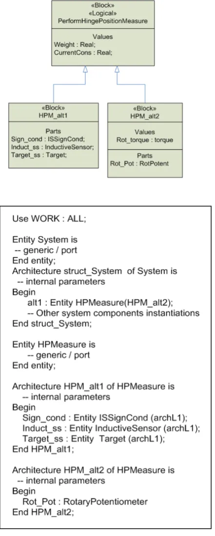
At architectural level, alternatives can be view as different arrangement of components. In SysML, Two alternatives will be own different parts in its parts compartment, and will share common traceability link toward top level effectiveness metrics or performance parameter. For example, two architecture alternatives will include respectively an inductive sensor, and rotary potentiometer. Both sensors add some weight to mechanical parts, but only the last will introduce a rotational torque to rotational movement due to friction of its internal parts.
Such relations can be modelled as an inheritance link between a functional, implementation-free block witch represent the common design characteristics with its effectiveness drivers, and some derived physical alternatives owning theirs own parts. Logical component will typically have some satisfaction links toward set of requirements, providing traceability of requirements onto inherited architecture alternatives block. Some architectural alternatives will inherit from multiple functional blocks, as they are involved in multiple system functions[8,9].
[image:4.595.305.526.57.608.2]Following is a simplified example, showing two design alternatives for performing a position measurement. Two architectures are therefore implemented for the same entity HPMeasure. Selection of current used architecture (HPM_arch2) is realised by the component instantiation in upper level system architecture body (HPM_arch2) is realised by the component instantiation in upper level system architecture body
Fig 1 : VHDL-AMS translation of architecture alternative.
C. Interconnecting system components
Last section showed how components can be instantiated from SysML structural hierarchy, allowing description of multiple design alternatives [10,11]. Next step is to realise components interconnection at a given level of structural hierarchy. For this purpose, SysML flowport and signal constructs are translated into port and port map in VHDL AMS instructions.
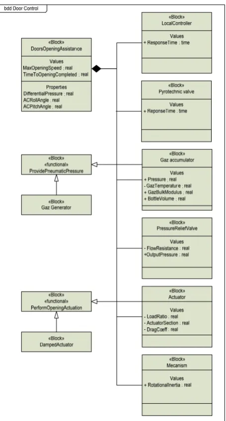
‘SigCond’. First one retrieve a position angle from system environment and transforms it into a voltage value. Second parts retrieve this value and apply a simple processing, providing a binary value as output. This output is then transmitted to system environment. First, outer flowports, wich enable communication between system and its environment are simply reported onto VHDL-AMS entity of system. Flowports direction define IN or OUT attribute of associated port declaration.
HPMeasure and SigCond entities are also declared, including its associated flowport input and output.
[image:5.595.309.537.346.771.2]Because two components are interconnected in system architecture, a local signal, called ‘interm’ has to be declared into system architecture. This local signal is typed according to port type of the components (which must be equal). HPMeasure and SigCong are then instantiated in architecture body of system. Then, it is necessary to map formal port (declared into HPMeasure and SigCond entities declaration) onto actual ports that are declared as System entity declaration and local signal declaration. Figure bellow presents SysML and VHDL-AMS translation of same system structure.
Fig 2 : VHDL-AMS translation of SysML Part interconnection
Therefore, followings steps has been performed, after entity and architecture declaration, to interconnect components of a system:
1/ From SysML Top Level System Block to lower level components, declare port according to flowport direction and name.
2/ From Flow port and SysML association between components, at each level, declare intermediary signal, typed with SysML flow port type.
3/ Instantiate component into top level architecture, (with optional architecture specification).
4/ Map components formal ports onto actual embedding block and its intermediary signals.
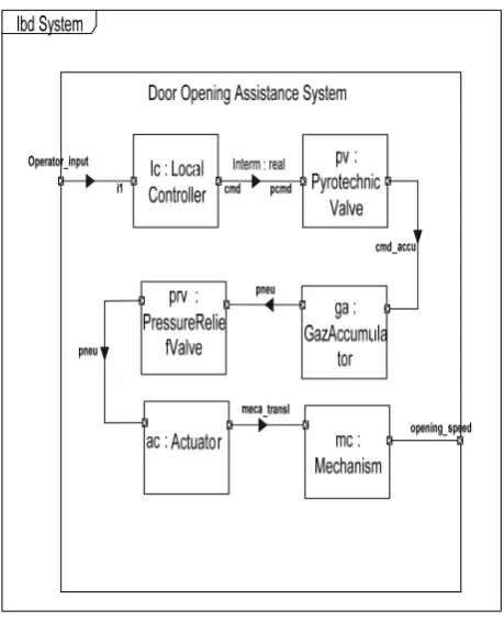
IV. CURRENT APPLICATION
Fig 3 : SysML Structural description of application
V. PERSPECTIVES
We look forward to generalise such approach by different case studies; the methodology can be extended to “systems of systems” as each class in SysML can represent a specific system; the object oriented design paradigm is well suited for systems families [11,12,13]. Effectively, Research in this area would seek to develop and apply notions from such areas as complex adaptive system and knowledge management and would seek to develop more of a methodological basis for system family architecting and design. Development of a methodological basis for the design and architecting of system families would do much to enhance present abilities to design loosely coupled and virtual organizations and to enable better architectures for these enterprises that would do much to support interoperability and integration[14,15]; the issue of interoperability in simulation is a critical issue in this context.
VI. CONCLUSION
In this paper we have introduced some rules to obtain simulable model from high level, object oriented structural descriptions. Principles described here will be implemented at tool level, along with current and previous work on behavioural model transformation from UML/SysML toward VHDL-AMS. Eventually, this will allow a complete, requirement-driven modelling and simulation methodology for system design.
REFERENCES
[1] OMG, UML for System Engineering RFP, -
ad/03-03-41 (28 March, 2003). http://syseng.omg.org/UML_for_SE_RFP.htm
[2] MOG SysML Specification language, v1.0. formal/2007-09-01
http://www.omg.org/technology/documents/formal/sys ml.htm
[3] A.E.K Sahraoui, D. Buede, A. Sage : systems engineering research, International journal of systems science and systems engineering. July 2008, springerlink
:http://www.springerlink.com/content/f6369550838743 65/
[4] Agarwal, R & Tanniru, MR 1990, 'Knowledge Acquisition Using Structured Interviewing: An Empirical Investigation', Journal of Management Information Systems, vol. 7, no. 1, pp. 123-40.
[5] Alderson, A 1991, 'Meta-case Technology', European Symposium on Software Development Environments and CASE Technology, Konigswinter, Germany, June 17-19.
[6] Alexander, I 2007, Requirements Engineering Tools and
Vendors, 2007, http://easyweb.easynet.co.uk/~iany/other/vendors.htm
[7] Alho, K & Sulonen, R 1998, 'Supporting Virtual Software Projects on the Web', Seventh IEEE International Workshop on Enabling Technologies: Infrastructure for Collaborative Enterprises (WET ICE '98), Stanford, USA, June 17-19.
[8] American Society for Quality 2006, Glossary, <http://www.asq.org/glossary/index.html>.
[9] Andreou, AS 2003, 'Promoting software quality through a human, social and organisational requirement
[10] Ebel, Nadine, ITIL V3 Basiswissen, Addison-Wesley, 2008
[11] Yin, RK 1994, Case Study Research: Design and Methods, Second edn, Sage, Thousand Oaks, USA. [12] Young, E 2004, Artificial Neural Network in PHP,
2005,
<http://coding.mu/archives/2004/03/19/artificial_neural _network_in_php/>.
[13] Yourdon, E 1989, Modern Structured Analysis, Prentice Hall, Englewood Cliffs, USA.
[14] Yu, ESK 1997, 'Towards Modeling and Reasoning Support for [1] Early-Phase Requirements Engineering', Third IEEE International Symposium on Requirements Engineering, Washington D.C., USA, January 5-8.