Evaluation of Machinability of Austempered Spheroidal Graphite Cast Iron
for Continuous Casting
*1Akihiko Ikuta
*2, Minoru Hatate and Tohru Nobuki
Department of Mechanical Engineering, Faculty of Engineering, Kindai University, Higashi-Hiroshima 739–2116, Japan
The machinability of austempered spheroidal graphite cast iron made by continuous casting (A-FCD600) was investigated. In this study, spheroidal graphite cast iron made by continuous casting (FCD600) was used to examine the influence of the austempering on machinability. In addition, austempered gray cast iron made by continuous casting (FC250) was used to examine the influence of the morphology of graphite on machinability. From the results of a tool wear test using continuous turning, the machinability decreased in the order of FC600, A-FC250 and A-FCD600. When relative machinability ratings between each material were calculated using tool life equations decided by the result of the tool wear test, the machinability of A-FCD600 was approximately 1.9 times inferior to FCD600, and approximately 1.3 times inferior to A-FC250. One characteristic of A-FCD600 was that its mechanical properties were relatively near steel. Therefore, a similar tool wear test was carried out with a P10 cemented carbide tool for steel. In this case, the tool life extended 25% compared to the K10 cemented carbide tool for cast iron. These results suggest that tool life can be improved in A-FCD600 cutting when tools for steel are used. [doi:10.2320/matertrans.F-M2016820]
(Received March 14, 2016; Accepted June 2, 2016; Published July 1, 2016)
Keywords: austempered spheroidal graphite cast iron, machinability, continuous casting, tool life, tool wear
1. Introduction
There are already reports about the machinability of
aus-tempered spheroidal graphite cast iron (shown as ADI)1–7).
Amongst these, one report states that the machinability of ADI using spheroidal graphite cast iron made by continuous casting is superior to the machinability of a general ADI us-ing spheroidal graphite cast iron made by sand mold
cast-ing8). The influence of the matrix has already been reported
regarding the machinability of all ADI. Another factor that has a great influence on the machinability of cast iron is graphite. Therefore, the machinability of cast iron is regarded
as generally excellent9). However, because the microstructure
of the matrix is transformed by austempering as mentioned above, ADI changes into a difficult-to-machine material. Be-cause the graphite exists both before and after austempering in ADI, it seems that the influence of the graphite and the matrix must both be considered regarding the actual machin-ability of ADI. Therefore, even though it has been reported that the machinability of ADI using a spheroidal graphite cast iron made by continuous casting is excellent, it is important that the influence of the graphite and the matrix are made clear.
It is the aim of this study to clarify the quantified relative machinability of ADI using spheroidal graphite cast iron made by continuous casting, from the viewpoint of tool life, by means of cutting tests. Gray cast iron and spheroidal graphite cast iron made by continuous casting were used to examine the influence of the graphite and the matrix, and the machinability of the two types of cast iron was compared.
2. Experimental Procedure
2.1 Materials
Commercial FCD600 and FC250 made by continuous
casting were used as the work materials in this study. The chemical composition of FCD600 and FC250 is shown in Ta-ble 1. The chemical composition of the tool materials used for the cutting tests is shown in Table 2. FCD600 and FC250 are cylindrical rods with a diameter of 66.5 mm and a length of 350 mm. Irrespective of austempering, the work materials were used for the cutting tests after 0.5 mm of the surface was removed by machining. The work materials were maintained at 1173 K for 7.2 ks, at 593 K in a salt bath for 7.2 ks more, and were then air-cooled. At this time, a continuous furnace with a methanol atmosphere was used to prevent decarbon-ization.
2.2 Investigation method of characteristics of the aus-tempered cast iron
The microstructure was observed to investigate the charac-teristics of the austempered cast iron, and tensile strength and Vickers hardness distribution were measured. Before optical microscopy, all of the test samples were polished and etched using a 3% natal reagent. The tensile strength was investigat-ed using a specimen of 8 mm and a gauge length of 30 mm
with an elastic stress rate of 0.5 mm/min. The micro Vickers
hardness distribution was investigated every 0.5 mm from the surface towards the axis center of the cylindrical rod, with a load of 0.98 N and a load time of 15 s.
2.3 Cutting test
A cutting test to compare the cutting characteristics of aus-tempered FCD600 and FC250 made by continuous casting (after shown as A-FCD600 and A-FC250 respectively) was carried out. The work materials used for the continuous cut-ting test were machined in a general-purpose lathe to removed 0.5 mm of the oxide film from the surface of the cylindrical rod. In the cutting test, the work materials were machined without the use of cutting fluid at cutting speeds of 100, 200
and 365 m/min, with a cutting feed of 0.2 mm/rev and a
depth of cut of 0.5 mm. The tool materials used were cement-ed carbide of grade K10 of WC-Co composition system with high toughness for cast iron, and P10 of WC-TiC-TaC-Co *1
This Paper was Originally Published in Japanese in J. JFS 88 (2016) 37– 42.
*2
composition system, with excellent hardness at high tempera-tures, and high toughness for steel. A cutting tool of 12.7 mm
width × 12.7 mm length × 4.76 mm thickness and a corner
radius of 0.8 mm was used. The cutting test was sometimes paused, and the machinability was evaluated using the
maxi-mum width of the flank wear (VB) on the major flank of the
cutting tools, observed and measured by an optical
micro-scope. When the maximum width of the flank wear (VB)
de-veloped to 0.7 mm, the cutting test was ended. The appear-ance of the cutting chips which were produced at the time of the cutting tests, were observed using an optical microscope, and the microstructures of the near surface in the cross sec-tion were observed using a scanning electron microscope.
3. Results and Discussions
[image:2.595.49.547.85.125.2]3.1 Characteristics of work materials
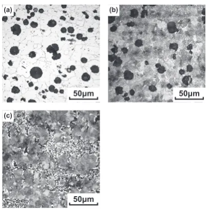
Figure 1 shows the microstructures of FCD600, A-FCD600 and A-FC250 at a position 2 mm in from the cylindrical rod surface. The microstructure of the FCD600 matrix was the ferrite in Fig. 1(a). In Fig. 1(b), the microstructure of the A-FCD600 matrix was on the whole like the bainite, and the shape of the graphite was spherical, similar to FCD600. In Fig. 1(c), the microstructure of the A-FC250 matrix was also on the whole like bainite, and the shape of the graphite was eutectic graphite. Compared to A-FCD600, FCD600 was the material in which the shape of the graphite was similar but the microstructure of the matrix was different, and A-FC250 was the material in which the shape of the graphite and the micro-structure of the matrix were both different. From these re-sults, it seems that materials satisfying the purpose of this study have been produced.
Figure 2 shows the tensile strength of FCD600, A-FCD600 and A-FC250. Though the tensile strength of FCD600 before austempering as a standard material was 623 MPa, it seems that a sufficient effect of austempering was obtained, because the tensile strength of A-FCD600 was 1321 MPa. On the oth-er hand, the tensile strength of A-FC250, which was a com-parison material to examine the influence of the shape of graphite, was 499 MPa. Though the tensile strength of A-FC250 was remarkably lower than the tensile strength of A-FCD600, and was lower than the tensile strength of FCD600, it was definitely higher than the tensile strength of FC250 before the austempering. Therefore, it seems that a sufficient effect of austempering is also obtained in A-FC250.
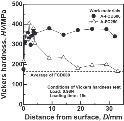
Figure 3 shows Vickers hardness distributions from the
surface towards the axis center of the cylindrical rod. Though the Vickers hardness in A-FCD600 was almost constant as far as the area around the axis center of the cylindrical rod, the Vickers hardness in A-FCD250 decreased from the surface towards the axis center of the cylindrical rod. However, it seems that the effect of austempering is obtained in both A-FCD600 and A-FC250 because Vickers hardness in A-FC250 is similar to A-FC600, at about 350 HV from the surface to about 4 mm inside. Therefore, in the cutting tests of A-FCD600 and A-FC250, the work materials were ma-chined from the surface to 2 mm inside.
Fig. 1 Microstructures of (a) FCD600, (b) A-FCD600 and (c) A-FC250.
Fig. 2 Tensile strengths of FCD600, A-FCD600 and A-FC250. Table 1 Chemical composition of cast iron (mass %).
Material C Si Mn P S Cu Ni Cr Ti
FCD600 3.10–3.70 2.50–3.20 <0.60 <0.100 <0.020 - - - 0.020–0.050
FC250 2.70–3.85 2.30–3.20 <0.80 <0.150 <0.040 - - - 0.10–0.40
Table 2 Chemical composition of tool material (mass %).
Grade WC Co NbC TiC + TaNbC
K10 92 6 2
[image:2.595.323.527.150.354.2] [image:2.595.46.292.167.207.2] [image:2.595.322.524.405.586.2]3.2 Tool wear in cutting tests
Figure 4 shows the results of the measurement of
maxi-mum width of flank wear (VB) when FCD600, A-FCD600
and A-FC250 were machined in cutting tests. In Fig. 4 (a), the tool lives of FCD600 were 94, 14 and 4 min with cutting
speeds of 100, 200 and 365 m/min respectively. In FCD600,
which has superior machinability, it seems that the morphol-ogy of the tool wear is mild wear because the tool wear curves are not straight lines even at the highest cutting speed of
365 m/min. In Fig. 4 (b), the tool lives of A-FCD600 were
22, 2 and 1 min with cutting speeds of 100, 200 and 365 m/
min respectively. Comparing Fig. 4 (b) with Fig. 4 (a), the machinability of A-FCD600, which is austempered FCD600,
can be seen to be markedly lower. In Fig. 4 (c), the tool lives of A-FC250 were 50, 2 and 1 min with cutting speeds of 100,
200 and 365 m/min respectively. The tool lives of A-FC250
were similar to A-FCD600 with cutting speeds of 200 and
365 m/min, and the tool life of A-FC250 was inferior to
FCD600 but was superior to A-FCD600 with a cutting speed
of 100 m/min. From the results of Fig. 4 (a)–(c), it seems that
the machinability of A-FCD600 is different from the machin-ability of FCD600 because of the effect of the austempering, and from the machinability of A-FC250, mainly because of the shape of the graphite.
Figure 5 shows the tool wear on major flank, minor flank
and rake faces with a cutting speed of 100 m/min as an
exam-ple of the wear conditions in machined FCD600, A-FCD600 and A-FC250 which had reached the end of their tool lives. In
Fig. 5 (a)–(c), the maximum width of flank wear (VB) in all
cases was similar because all the tools had reached the end of their tool lives. On the other hand, when the wear conditions for FCD600 as shown in Fig. 5 (a) were compared with the wear conditions for A-FCD600 and A-FC250 as shown in Fig. 5 (b) and (c), large wear on the rake face was observed. In addition, the morphology of the tool wear on the major flank was observed, to be groove wear, as in Fig. 5 (b) and (c). From the wear conditions on the rake face, it is suggested that the cutting temperature in A-FCD600 and A-FC250 is high, and from the wear conditions on the flank, it is suggested that the mechanical properties of the work materials greatly influ-ence the tool wear in A-FCD600 and A-FC250. When Fig. 5
(c) is compared with Fig 5 (b), the depth of crater wear (KT)
in A-FCD600 can be seen to be deeper than A-FC250, though the area of the tool wear on the rake face in A-FC250 is larger. From these results, even for materials austempered with the same process, it is suggested that the cutting conditions for A-FCD600 are more severe.
Fig. 3 Distribution of Vickers hardness in FCD600, A-FCD600 and A-FC250 rods in radial direction.
Fig. 4 Relationship between maximum width of flank wear (VB) and cutting time in (a) FCD600, (b) A-FCD600 and (c) A-FC250.
[image:3.595.65.265.257.451.2] [image:3.595.127.469.510.617.2] [image:3.595.129.468.658.769.2]3.3 Examination of tool life
From the results of the tool wear tests shown in Fig. 4, a general Taylor s tool life equation was derived to evaluate quantitatively the influence of different work materials on the
tool life10). Figure 6 shows the Taylor s tool life equation
de-rived. After each wear curve was calculated by the least-squares method from Fig. 4, the obtained function was used to derive the cutting time (tool life) before the tool reached
the end of its life, at cutting speeds of 100, 200 and 365 m/
min. Next, the provided tool life for each cutting speed was plotted into a cutting speed-cutting time graph, and the tool life equation was derived by the least-squares method. The obtained tool life equations for FCD600, A-FCD600 and A-FC250 are the eqs. (1), (2) and (3) respectively, as follows. Here, V is the cutting speed and T is the tool life.
FCD600: e6.39=VT0.40 (1)
A-FCD600: e5.56=VT0.34 (2)
A-FC250: e5.64=VT0.27 (3) In Fig. 6, the tool life of FCD600 is longer than A-FCD600 and A-FC250 at all cutting speeds. Though the inclination of the straight line for A-FCD600 is similar to FCD600, the tool life of A-FCD600 decreases remarkably. Though the inclina-tion of the straight line for A-FC250 is different to FCD600 and A-FCD600, the tool life of A-FC250 at all cutting speeds is shorter than FCD600 and is longer than A-FCD600. For an indication to compare machinability under the same cutting conditions using the eqs. (1)–(3), the cutting speed with a tool
life of 20 minutes (FV20) was calculated11). The results were
as follows. FV20 for FCD600, A-FCD600 and A-FC250 is
181.3, 94.7 and 126.4 m/min respectively. When the ratio for
each FV20 was calculated like the machinability rating11), with
FV20 for FCD600 as a base, A-FCD600 was 52.2% of FCD600
and A-FC250 was 69.7% of FCD600. In addition, when the ratio was calculated with A-FCD600 and A-FC250, A- FCD600 was 74.9% of A-FC250. From these results, though it is restricted to a certain set of conditions, the machinability of A-FCD600 is about 1.9 times inferior to FCD600 and
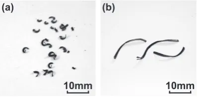
about 1.3 times inferior to A-FC250, and the machinability of A-FC250 is about 1.4 times inferior to FCD600. Therefore, it is suggested that by comparing A-FCD600 with FCD600, the influence on machinability of change to the matrix due to aus-tempering can be estimated. Similarly, it is suggested that by comparing A-FCD600 with A-FC250, the influence on ma-chinability of the shape of the graphite can also be estimated. As an example of the observation results, Fig. 7 shows the surfaces of the cutting chips which had been in contact with the rake face, produced by machining A-FCD600 and A-FC250. In Fig. 7 (a), which shows the cutting chips of A-FCD600, the graphite indicated by the arrows was ob-served to have maintained its shape relatively well, though the original spheroidal shape had collapsed. In Fig. 7 (b), which shows the cutting chips of A-FC250, graphite of a clear shape was not observed. From these results, although the graphite is the initiation point for the production of the cut-ting chips, it is suggested that the deformation of the matrix in A-FCD600 is not easy because the shape of the graphite is spherical. And it is suggested that the deformation of the ma-trix in A-FC250 is easy because dislocation is easy as result of the crushed graphite being the initiation point for the pro-duction of the cutting chips. These results are clear from the overview observations of the cutting chips, and Fig. 8 shows the result of these observations. In Fig. 8 (a), in A-FCD600 where deformation of the cutting chips may be difficult, the length of the cutting chips was short, and the shape of the cutting chips was the shear type. In Fig. 8 (b), in A-FC250 where deformation of the cutting chips may be easy, the length of the cutting chips was long, and the shape of the cutting chips was the flow type.
Fig. 6 Relationship between cutting speed and tool life.
Fig. 7 Surfaces of cutting chips in contact with rake face (a) A-FCD600 and (b) A-FC250, machined with a cutting speed of 100 m/min.
[image:4.595.68.265.74.264.2] [image:4.595.326.525.76.174.2] [image:4.595.327.526.238.338.2]3.4 Improvement of tool life by different tool materials
From the results mentioned above, the influence of the ma-trix and the graphite on the machinability of A-FCD600 has been made clear. The Vickers hardness, one of the mechanical properties, was focused upon because the main morphology of tool wear was the mechanical wear in A-FCD600. The Vickers hardness of A-FCD600, one of the mechanical prop-erties as mentioned above, was 350 HV, and it was compared with the mechanical property of medium and high carbon steel which basically did not contain any alloy elements. For example, the hardness of quenched and tempered SK140 was
less than 772 HV (63 HRC)12) and the hardness of quenched
and tempered S55C was 241–301 HV (229–285 HB)13).
From these results, it can be seen that the hardness of A-FCD600 is between quenched and tempered medium car-bon steel and quenched and tempered high carcar-bon steel. It has been reported that ADI is hardened by strain-induced marten-sitic transformation at cutting, and receives a tempering effect
by the cutting temperature rise at high cutting speed8). In this
study, however, it seems that ADI receives the effects of quenching and tempering together. Therefore, it seems that A-FCD600 is similar to the mechanical properties of hard-ened steel rather than cast iron, although this is only tentative. It was examined whether improvement of the tool life was possible by using a cemented carbide tool of P10 grade (shown as P10) for steel cutting rather than a cemented car-bide tool of K10 grade (shown as K10) for cast iron cutting.
Figure 9 shows the measurement results for the width of
flank wear (VB) when A-FCD600 was cut using a P10 tool
with a cutting speed of 100 m/min. The width of flank wear
when a P10 tool was used decreased in comparison to a K10 tool, and the tool lives were 20 min for the K10 tool and 25 min for the P10 tool. There was a clear difference between K10 and P10, an extension of tool life by 25%.
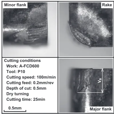
Figure 10 shows the tool wear on the major flank, minor flank and rake faces of a P10 tool which had reached the end of its tool life. The superiority of a P10 tool regarding the wear morphology was clear, because the wear of the face de-creased clearly and the wear of the flank was not the groove
shaped boundary wear seen with a K10 tool. From these re-sults, it is suggested that the use of a P10 tool is effective as one of the methods for tool life improvement for A-FCD600 cutting because the tool life is improved clearly just by using a P10 tool of almost the same price as a K10 tool. In addition, it has been reported that cBN tools are suitable as a method
for cutting ADI with high efficiency14–17). Generally, cBN
tools are suitable for the cutting of hardened steel. This result is similar to the result of this study, it corresponds with the fact that a cutting tool for hardened steel is effective in the cutting of ADI.
4. Conclusion
The influences of graphite and the matrix on the machin-ability of ADI using spheroidal cast iron made by continuous casting were investigated in this study. The machinability re-sults made clear from the viewpoint of tool life are as follows. (1) From the results of the cutting tests, machinability de-creases in the order of FCD600, A-FC250 and A-FCD600.
(2) From the tool life equation, although it is restricted to certain conditions, the machinability of A-FCD600 was about 1.9 times inferior to that of FCD600, and about 1.3 times in-ferior to that of A-FC250, and the machinability of A-FC250 was about 1.4 times inferior to that of FCD600.
(3) The possibility that the machinability of A-FCD600 can be improved by the choice of tool materials is suggested, be-cause the machinability of A-FCD600 is relatively similar to steels.
Acknowledgments
A part of this work was supported by a Research Grant for Young Scientists from the Japan Foundry Engineering Soci-ety. The work materials were supplied by Japan Casting Co., Ltd.
Fig. 9 Relationship between maximum width of flank wear (VB) and cut-ting time in A-FCD600, machined by P10 cemented carbide tool with
[image:5.595.67.268.68.264.2] [image:5.595.325.525.72.271.2]REFERENCES
1) H. Kiso, M. Koyama and T. Taguchi: IMONO 61 (1989) 615–619. 2) K. Shintani, H. Kato, G. Shiotani and Y. Fujimura: IMONO 63 (1991)
523–527.
3) Y. Tanaka, A. Shimizu and H. Yokouchi: IMONO 65 (1993) 93–98. 4) T. Wada, J. Fujiwara, S. Hanasaki and M. Yasutomi: Trans. Jpn. Soc.
Mech. Eng. C 64 (1998) 4065–4071.
5) T. Fujita, K. Sekiya, R. Kitagawa, N. Koike and K. Ogi: J. Jpn. Soc. Precis. Eng. 60 (1994) 1314–1318.
6) T. Fujita, K. Sekiya, R. Kitagawa, A. Sawamoto and K. Ogi: J. Jpn. Soc. Precis. Eng. 62 (1996) 1315–1319.
7) S. Yamamoto, H. Nakajima and H. Miyaji: Tetsu-to-Hagane 81 (1995) 721–726.
8) A. Ikuta, M. Hatate and T. Nobuki: J. JFS 87 (2015) 231–238. 9) K. Uehara: J. JFS 70 (1998) 425–431.
10) The Japan Society for Precision Engineering Eds: Precision Machining Handbook, (Corona Publishing Co., Ltd., Tokyo, 1992) pp.127. 11) The Japan Society for Precision Engineering Eds: Precision Machining
Handbook, (Corona Publishing Co., Ltd., Tokyo, 1992) pp.128. 12) K. Yokota, T. Sato, S. Ohwaku and N. Kayama: Metals for Machines,
(Mechanical Institute, Tokyo, 1966) pp.207.
13) The Iron and Steel Institute of Japan Eds: Steel Handbook IV (Maruzen Co., Ltd., Tokyo, 1981) pp.112.
14) K. Shintani, H. Kato, Y. Fujimura and A. Yamamoto: J. Jpn. Soc. Precis. Eng. 56 (1990) 2261–2266.
15) H. Kato, K. Shintani and Y. Fujimura: Jpn. Soc. Mech. Eng. C 57 (1991) 3027–3031.
16) K. Shintani and N. Suzuki: J. Jpn. Soc. Precis. Eng. 61 (1995) 804–808. 17) K. Shintani, H. Sugiyama, M. Goto and H. Kato: J. JFS 70 (1998) 402–