Machinability of Austempered Spheroidal Graphite Cast Iron Made
by Sand Mold and Continuous Casting Methods
*1Akihiko Ikuta
*2, Minoru Hatate and Tohru Nobuki
Department of Mechanical Engineering, Faculty of Engineering, Kindai University, Higashi-Hiroshima 739–2116, Japan
In this study, the machinability of austempered spheroidal graphite cast iron made by different casting methods was investigated. Spheroi-dal graphite cast iron samples made by sand mold casting and continuous casting, respectively ADI-S and ADI-C, were used. From the results of cutting tests, the machinability of ADI-C was always excellent compared with that of ADI-S at cutting speeds from 100 to 365 m/min. The feed and thrust forces of ADI-S were higher than those of ADI-C at high cutting speeds, although their-cutting resistance was almost the same at low cutting speeds. In addition, the microstructure of ADI-S chips was found to be greatly deformed near the chip-tool interface for ADI-S compared with ADI-C. It has been reported that there always exists retained austenite in austempered spheroidal graphite cast iron, and that the retained austenite transforms to deformation-induced martensite on the machined surface when the austempered spheroidal graphite cast iron is machined. From the results of the comparative analysis of ADI-S and ADI-C, the average relative volume ratio of retained austenite increased with increasing cutting speed for both ADI-S and ADI-C, and was about double in the case of ADI-S at high cutting speeds such as 365 m/min. From these results, it is clear that the retained austenite in both ADI-S and ADI-C does not transform to deformation induced martensite at high cutting speeds, and that ADI-C can be machined at cutting temperatures and with cutting resistances lower than those necessary for ADI-S, suggesting that the machinability of ADI-C is better than ADI-S. [doi:10.2320/matertrans.F-M2016815]
(Received December 15, 2015; Accepted May 9, 2016; Published June 10, 2016)
Keywords: austempered spheroidal graphite cast iron, machinability, sand mold casting, continuous casting, retained austenite
1. Introduction
Austempered spheroidal graphite cast iron (shown as ADI) has many excellent characteristics, and is already being used for important structural members1). However, the increased use of ADI may be inhibited because although it has many excellent characteristics the machinability is inferior to much cast iron. Therefore, there are already reports about the ma-chinability of ADI2–8). Amongst these, there are reports that the use of the cBN tool is effective as a kind of high efficiency machining method, considering the difficulty of machining ADI among them9–11). From these reports, a method that solves to an extent the problems when ADI is machined has already been shown.
On the other hand, actual ADI is judged to have no prob-lems when the predetermined requirements are satisfied in the quality inspection after the austempering. In this case, it is a fact that the conditions other than the chemical composition before the austempering are not considered. However, there are many indications that the machinability is not constant, regardless of the difficulty in machining, when similar ADI which has satisfied the predetermined requirements is ma-chined. Even when the characteristics of ADI are similar after the austempering, it seems that the conditions before the aus-tempering, mentioned above, have some kind of influence on machinability. Therefore, although the influence of the aus-tempering has been already considered when the machinabil-ity of ADI is examined, it is necessary to consider differences before austempering that have so far hardly been considered, namely differences in the casting method12–14).
The influence that the casting methods has on the machin-ability of ADI was focused upon in this paper, and the
pur-pose of this paper is to make clear the differences in machin-ability in this case. After having investigated the influence that the casting methods have on the characteristics of ADI, various cutting tests were carried out. From the cutting tests, it was attempted to make clear the phenomena occurring during at the cutting of ADI, by examining cutting tools, cut-ting chips and work materials.
2. Experimental Procedure
2.1 Materials
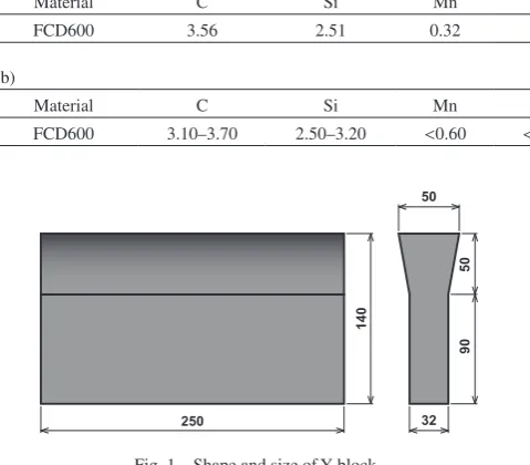
FCD600 made by sand mold casting and continuous cast-ing as the work materials and K10 grade cemented carbide as a cutting tool were used in this study. The chemical composi-tion of the FCD600 made by sand mold casting and continu-ous casting is shown in Table 1. In FCD600 made by sand mold casting, a Y block as shown in Fig. 1 was cast by the method shown in Table 2. In FCD600 made by continuous casting, a commercial plate with a width of 155 mm, a length of 300 mm and a thickness of 35 mm was used. After all cast-ing materials were machined to 120 mm width × 120 mm length × 27 mm thickness, or a cube of 27 mm, they were austempered. The casting materials were maintained at 1173 K for 1.5 h, at 593 K in a salt bath for 1 h more, and were then air-cooled. At this time, RX gas as the main gas and enriched propane gas were used in the continuous furnace.
2.2 Investigation method of ADI characteristics
The microstructure was observed to investigate the charac-teristics of ADI, and tensile strength and Vickers hardness distribution were measured. Before optical microscopy, all of the test samples were polished and etched using a 3% nital reagent. The tensile strength was investigated using a speci-men of 8 mm in diameter and a gauge length of 25 mm with an elastic stress rate of 0.5 mm/min. Micro Vickers hardness distribution was investigated every 0.5 mm from the surface *1
This Paper was Originally Published in Japanese in J. Japan Foundry En-gineering Society 87 (2015) 231–238.
*2
towards the center of the ADI plate with a load of 100 gf and a load time of 15 s.
2.3 Method of cutting test
In a test to compare the cutting characteristics of austem-pered spheroidal graphite cast iron made by sand mold cast-ing and continuous castcast-ing (respectively shown as ADI-S and ADI-C), the austempered materials of 120 mm width × 120 mm length × 27 mm thickness was machined to 118 mm width × 118 mm length × 25 mm thickness, and the 118 × 25 mm face was intermittently cut using a machining center. In the cutting test, ADI was machined without the use of cut-ting fluid, at cutcut-ting speeds of 100, 200 and 365 m/min with a cutting feed of 0.2 mm/tooth and a depth of cut of 0.5 mm. A cutting tool of 12.7 mm width × 12.7 mm length × 4.76 mm thickness and a corner radius of 0.8 mm was used. The ma-chinability of ADI was evaluated using the maximum width of flank wear (VB) when ADI-S and ADI-C were machined under the same conditions. The cutting distances were decid-ed to 295, 118 and 14.75 m each with cutting spedecid-eds of 100, 200 and 365 m/min respectively, to develop the wear on all the faces of the cutting tools so that observation was easy. An optical microscope was used for the observation and mea-surement of the wear on all the faces of the cutting tools, and for the observation of microstructures in the cross sections of the cutting chips. The observation conditions for the micro-structures were the same as the conditions for investigating the characteristics of ADI. A contact type surface roughness meter was used for the measurement of the maximum height of profile (Rz) on work materials after the cutting test.
For the measurement of cutting resistance, a 25 × 25 mm face of ADI with 120 mm width × 120 mm length × 27 mm thickness that had been machined to 25 mm width × 25 mm height × 55 mm length was machined intermittently using an exclusive jig and a general purpose lathe. At this time, the cutting conditions were the same as the cutting conditions for investigating the machinability of ADI. A strain gauge type tool dynamometer was used for the measurement of cutting resistance, with a sampling frequency of 20 kHz and a sam-pling time of 10 or 20 s.
The average relative volume ratio of retained austenite was measured by X-ray diffractometer on the surface of the ma-chined ADI. For the measurement of average relative volume ratio of retained austenite, the surface of ADI of a cube of 27 mm that had been machined to a cube of 25 mm was cut intermittently using a machining center. Again, the cutting conditions were the same as the cutting conditions for inves-tigating the machinability of ADI. The diffraction peaks for the average relative volume ratio of retained austenite were measured for [110], [200] and [211] of α-Fe and [111], [200], [220] and [311] of γ-Fe with a target of copper, an accelera-tion voltage of 40 kV, a tube current of 100 mA, a step angle of 0.02 , and a scan speed of 0.1 s/step.
3. Results and Discussions
3.1 Results of austempering
[image:2.595.52.292.104.314.2]Figure 2 shows the microstructures on ADI-S and ADI-C before and after the austempering. When the microstructure of ADI-C was compared with ADI-S before the austemper-ing, a nearly pearlite matrix in ADI-S and a clear ferrite ma-trix in ADI-C were observed, indicating that the both micro-structures were totally different. It seems that the cooling conditions are different when both types of ADI are cooled. In addition, it seems that the microstructure of ADI-C is slightly influenced by the titanium15). On the other hand, the matrix of both types of ADI were on the whole like the bain-ite, though ADI-S was more like martensite when the micro-structure of ADI-S was compared with ADI-C. From these results, it was judged that ADI-S and ADI-C were austem-pered appropriately. However, the microstructure of ADI-C is not similar to ADI-S because the chemical composition is designed in each cast iron to be suitable for each casting method, and it seems that this influence the machinabilities. Figure 3 shows the tensile strength of cast iron (FCD600) made by sand mold casting and continuous casting before and after austempering. Though the tensile strength of FCD600 made by continuous casting before austempering was higher than FCD600 made by sand mold casting, the tensile strength of ADI-S made by sand mold casting after austempering was
Table 2 Conditions of sand mold casting (mass %).
Materials Additive agent Inoculant Spheroidizing agent Pig iron Steel Fe-75%Si Fe-75%Mn Cu Fe-50%Si Fe-45%Si-5.5%Mg
97.0 3.0 2.0 0.30 0.5 0.30 1.80
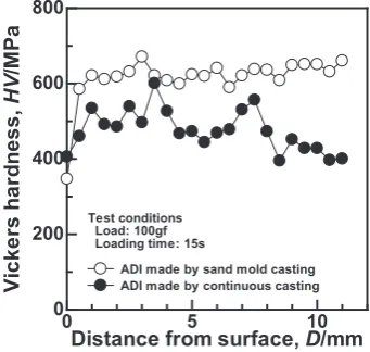
[image:2.595.46.291.359.399.2]higher than ADI-C made by continuous casting. Figure 4 shows the Vickers hardness distribution of ADI-S and ADI-C towards the inside from the surface. The Vickers hardness on the surface of both ADI-S and ADI-C decreased about 100 HV compared to internal hardness. The distribution of Vickers hardness was almost constant at about 600 HV in ADI-S and about 500 HV in ADI-C, though these figures fluctuated a little. From these results, the mechanical proper-ties and microstructures of cast iron are greatly different when casting methods are different before the austempering. The conditions of ADI-C are only a little different from ADI-S after austempering, and it is confirmed that the charac-teristics of ADI-S and ADI-C are almost the same as general ADI.
[image:3.595.70.269.68.270.2]3.2 Machinability comparison between ADI-S and ADI-C
Figure 5 shows an example result of the observation of cut-ting faces for the machinability comparison between ADI-S and ADI-C when the cutting conditions are the same. In Fig. 5 (a), which shows the case of machined ADI-S, there was a
Fig. 2 Microstructures of (a) FCD600 made by sand mold casting, (b) FCD600 made by continuous casting, (c) ADI made by sand mold casting and (d) ADI made by continuous casting.
Fig. 3 Tensile strength of FCD600 made by sand mold casting and contin-uous casting and ADI made by sand mold casting and contincontin-uous casting.
Fig. 4 Distribution of Vickers hardness in ADI made by sand mold casting and continuous casting.
[image:3.595.338.509.73.235.2] [image:3.595.326.527.299.728.2] [image:3.595.81.251.333.488.2]little the face wear, but large wear on flank was observed. The same flank wear as Fig. 5 (a) was observed in Fig. 5 (b), which shows the case of machined ADI-C. It follows that the main morphology of tool wear is the mechanical wear when ADI-S and ADI-C are machined. The maximum width of flank wear (VB) when ADI-S and ADI-C were machined at each cutting speed was measured because flank wear was ob-served in Fig. 5 (a) and (b). Figure 6 shows the results of the measurement of the maximum width of flank wear (VB) when FCD600 and ADI made by sand mold casting and continuous casting were machined with the same cutting conditions. The machinability of ADI-C is better than ADI-S since the maxi-mum width of flank wear is small when ADI-C is machined, at all cutting speeds. Figure 7 shows the results of measure-ment of surface roughness on the machined surface of ADI-S and ADI-C. Though the surface roughness of ADI-C was larger than ADI-S at a cutting speed of 100 m/min, it de-creased and was smaller than ADI-S when the cutting speed was increased. On the other hand, the surface roughness of ADI-S was almost constant at all cutting speeds.
3.3 Discussion of cutting resistance
There is a clear difference between the machinability of ADI-S and ADI-C. To investigate the reasons, the cutting
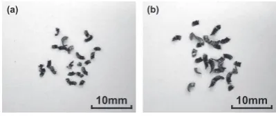
re-sistance of ADI-S and ADI-C was examined. Figure 8 shows these results. Though the cutting resistance of ADI-S was the almost the same as ADI-C at a cutting speed of 100 m/min as in Fig. 8 (a), there was a clear difference when the cutting speed became faster, and the cutting resistance of ADI-S be-came higher than ADI-C. From the results of Fig. 8 (b)–(d), it is clear that, regardless of the principal cutting force, differ-ences between ADI-C and ADI-S in the feed force and the thrust force (especially the thrust force). The surface rough-ness of ADI-S is larger than ADI-C at cutting speeds of 200 and 365 m/min as shown in Fig. 7 because it is generally re-ported that the thrust force affects the precision of the diame-ter of the work madiame-terial direction16). In addition, Fig. 9 shows an example of the results of observations of chips. From the results of measurement by image analysis, the lengths 1.73 mm in the case of ADI-S and 2.71 mm in the case of ADI-C at a cutting speed of 365 m/min, where these wear differences in the feed force and the thrust force when ADI-S and ADI-C were cut. The average chip length was longer for ADI-C than for ADI-S, though the shapes of the chips were the same. It seems that the average chip length of ADI-C gets longer because ADI-C has a lower hardness than ADI-S, as shown in Fig. 4, and has high ductility. Though the tendency of the chip lengths of ADI-S and ADI-C were the same, the difference of the chip length was only small when the cutting speed was low.
Fig. 6 Widths of maximum flank wear in ADI made by sand mold casting and continuous casting.
Fig. 7 Surface roughness on machined surface of ADI made by sand mold casting and continuous casting.
Fig. 8 (a) Cutting resistance, (b) principal cutting forces, (c) feed forces and (d) thrust forces in ADI made by sand mold casting and continuous casting.
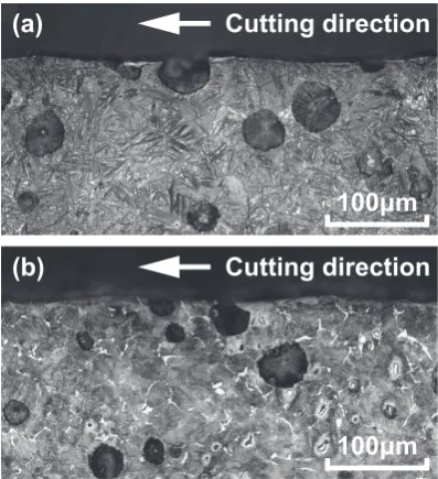
[image:4.595.76.256.70.241.2] [image:4.595.314.536.71.285.2] [image:4.595.84.252.288.451.2] [image:4.595.324.524.345.429.2]The microstructures at the cross section of the chips and the machined near surface on the work materials were ob-served to investigate the influence on work materials when cut. Figure 10 shows the microstructures at the cross section of the chips when ADI-S and ADI-C are machined with a cutting speed of 365 m/min. Greatly deformed graphite and plastic deformed matrix were observed near the interface with the rake in both ADI-S and ADI-C, and the deformity direction and flow direction of the chips were similar. Howev-er, the deformation became bigger in ADI-S when the feed and thrust force were increased, as shown in Fig. 8. There-fore, it is suggested that a cutting resistance bigger than ADI-C is applied at the cutting point when ADI-S is cut. On the other hand, Fig. 11 shows the microstructures at the cross section of the machined near surface on the work materials when ADI-S and ADI-C are machined with a cutting speed of 365 m/min. Both ADI-S and ADI-C were similar in that the graphite came off the machined surface. No damaged layer was observed in the matrix of the machined near surface in either ADI-S or ADI-C. However, because the cutting resis-tance is large and a relatively large deformation is observed in the chips, it seems that the machined surface is affected by something.
3.4 Discussion of retained austenite
[image:5.595.68.269.70.170.2]From the result mentioned above, it is inferred that the ma-chined surface of ADI-S and ADI-C is affected by something. Regarding the cutting of ADI, it has been already reported that the reason why ADI is a difficult-to-machine material is that retained austenite exists4,8,12,13). In these reports, all types of ADI have the characteristics of difficult-to-machine mate-rials because a lot of retained austenite existing in the ADI matrix transforms to strain-induced martensite with the cut-ting. Therefore, the average relative volume ratio of retained austenite was investigated in this paper.
Figure 12 shows the measurement result of the average rel-ative volume ratio of retained austenite on the machined sur-face of ADI-S and ADI-C. The results for the sursur-face of ADI-S and ADI-C are canceled by polishing the influence of machining as much as possible, and is shown as a cutting speed of 0 m/min for comparison. From Fig. 12, the average relative volume ratio of retained austenite is about 40% in ADI-S and about 20% in ADI-C, so the difference is double. When the cutting speed increases for ADI-C, the average rel-ative volume ratio of retained austenite continues to slightly increase and reaches about 25% at a cutting speed of 365 m/
min. On the other hand, the average relative volume ratio of retained austenite in ADI-S decreases at a cutting speed of 100 m/min, and increases afterwards when the cutting speed increases, reaching about 47% at a cutting speed of 365 m/
min. As a general relationship between the cutting speed and the cutting temperature, the cutting temperature becomes higher when the cutting speed increases. Though the retained austenite in cutting transforms to strain-induced martensite when the cutting temperature is less than the recrystallization temperature, it does not transform to strain-induced marten-site when the cutting temperature is more than the recrystalli-zation temperature. The cutting temperature may reach a high temperature depending on the cutting conditions. When the cutting temperature becomes very high, new austenite may be generated. When the mutual relationships between each of these phenomena are considered, originally ADI-C dose not transform readily to strain-induced martensite because there is little retained austenite in comparison with ADI-S. In addi-tion, it is suggested that the newly generated austenite is left
Fig. 10 Microstructures of ADI chips made by (a) sand mold casting and (b) continuous casting, machined with cutting speed of 365 m/min.
[image:5.595.325.526.73.253.2]Fig. 11 Microstructure of machined surface of ADI made by (a) sand mold casting and (b) continuous casting, machined with cutting speed of 365 m/min.
[image:5.595.69.268.225.443.2]slow in ADI-S, namely, low cutting temperatures. It seems that the retained austenite does not transform to strain-in-duced martensite like ADI-C when the cutting speed is fast in ADI-S, namely, at high cutting temperatures. However, it seems that the cutting resistance is large even when the cut-ting temperature is high because the matrix of ADI-S has high mechanical properties, and therefore does not deform regu-larly to chips. Therefore, it is suggested that the machinability of ADI-C is better than ADI-S because the retained austenite does not transform to strain-induced martensite at any cutting speed. Also, it is suggested that the machinability of ADI-S is inferior than ADI-C because the retained austenite transforms to the strain-induced martensite at low cutting speeds and the cutting resistance is large, though the retained austenite does not transform to strain-induced martensite at high cutting speeds.
The results of this study are slightly different from some studies that have already reported why the machinability of ADI is low. Regarding the low machinability of ADI because the retained austenite did not transform to strain-induced martensite, the difference between the results of this study and other studies4,12,13) was the cutting speed. Though the cut-ting speeds in this study were comparatively high, between 100–365 m/min, most cutting speeds in other studies were about 100 m/min. When the cutting speed is high as in this study, it has been reported that the volume ratio of retained austenite increases because the cutting temperature becomes higher with rising cutting speed8). Connected to the transfor-mation of the retained austenite to strain-induced martensite, it has been reported that the influence of the thrust force on the damaged layer of the machined surface is generally large when the cutting speed is low such as 10 m/min17). The re-sults of these reports correspond with the rere-sults of this study well. In addition, it seems that the mechanical properties of the matrix of ADI, such as hardness, are similar to hardened steels. In a report that investigated the cutting temperature of hardened steel, it has been reported that the cutting tempera-ture reached 673–1173 K with a cutting speed of more than 100 m/min, though the detailed cutting conditions were dif-ferent from this study18,19). Although the strain-induced mar-tensitic transformation start temperature (Md point) varies slightly according to chemical composition, it has been re-ported that this temperature is about 550 K20). In this study, it is suggested that the cutting temperature reaches at more than the Md point when the cutting speed is more than 100 m/min.
4. Conclusion
The influence of casting methods on the machinability of ADI was investigated in this study. Cutting tests were carried out to clarify the machinability differences of ADI with vary-ing castvary-ing methods, and the phenomena when ADI was cut
tance is almost the same with a cutting speed of 100 m/min. (3) When the cutting speed increases for ADI-C, the aver-age relative volume ratio of retained austenite continues to slightly increase. The average relative volume ratio of re-tained austenite in ADI-S decreases at a cutting speed of 100 m/min, and increases afterwards when the cutting speed increases. It increases to about double of ADI-C with a cut-ting speed of 365 m/min.
(4) The retained austenite does not always transform to strain-induced martensite with the cutting conditions of this study, and ADI-C has moderate ductility and therefore de-forms to chips easily. It is suggested that the machinability of ADI-C is better than ADI-S because the cutting resistance of ADI-C is low.
Acknowledgments
This work was supported by a Research Grant for Young Scientists from Japan Foundry Engineering Society.
REFERENCES
1) Textbook Editing Sectional Meeting for Production Engineering of the Cast Iron Eds: Production Engineering of the Cast Iron, (Sokeizai Cen-ter, Tokyo, 1999) pp.93–100
2) H. Kiso, M. Koyama and T. Taguchi: IMONO 61 (1989) 615–619. 3) K. Shintani, H. Kato, G. Shiotani and Y. Fujimura: IMONO 63 (1991)
523–527.
4) Y. Tanaka, A. Shimizu and H. Yokouchi: IMONO 65 (1993) 93–98. 5) T. Wada, J. Fujiwara, S. Hanasaki and M. Yasutomi: Trans. Jpn. Soc.
Mech. Eng. C 64 (1998) 4065–4071.
6) T. Fujita, K. Sekiya, R. Kitagawa, N. Koike and K. Ogi: J. Jpn. Soc. Precis. Eng. 60 (1994) 1314–1318.
7) T. Fujita, K. Sekiya, R. Kitagawa, A. Sawamoto and K. Ogi: J. Jpn. Soc. Precis. Eng. 62 (1996) 1315–1319.
8) S. Yamamoto, H. Nakajima and H. Miyaji: Tetsu-to-Hagane 81 (1995) 721–726.
9) K. Shintani, H. Kato, Y. Fujimura and A. Yamamoto: J. Jpn. Soc. Precis. Eng. 56 (1990) 2261–2266.
10) H. Kato, K. Shintani and Y. Fujimura: Jpn. Soc. Mech. Eng. C 57 (1991) 3027–3031.
11) K. Shintani and N. Suzuki: J. Jpn. Soc. Precis. Eng. 61 (1995) 804–808.
12) M. Takita, Y. Ueda, H. Shiraki, K. Naruse and Y. Kashiwagi: IMONO
61 (1989) 620–627.
13) T. Yoshida, K. Komatsu and S. Okada: IMONO 65 (1993) 221–226. 14) T. Ohide, M.N. Ahmadabadi and M. Saito: IMONO 67 (1995) 106–
110.
15) M. Sohma and T. Kanauchi: Bull. Fac. Eng., Hokkaido Univ. 147 (1989) 1–9.
16) K. Nakayama: J. Jpn. Soc. Precis. Eng. 30 (1964) 53–59.
17) R. Hikiji, K. Aburada, M. Harada, T Ueno and S. Yoshimitsu: Research reports of Kagoshima National College of Technology 35 (2000) 9–15 18) K. Oishi: J. Jpn. Soc. Precis. Eng. 59 (1993) 509–514.
19) H. Nakagawa, T. Hirogaki, K. Nishimura, Y. Kakino, Y. Kita and H. Ohtsuka: J. Jpn. Soc. Precis. Eng. 67 (2001) 834–838.