Effect of Hybrid Surface Treatment Composed of Plasma Nitriding
and DLC Coating on Friction Coef
fi
cient
and Fatigue Strength of Stainless Steel
Tatsuro Morita
1,+, Kouichi Andatsu
1, Satoshi Hirota
2, Tadashi Kumakiri
2,
Masaru Ikenaga
3and Chuji Kagaya
41Department of Mechanical and System Engineering, Graduate School of Science and Technology, Kyoto Institute of Technology,
Kyoto 606-8585, Japan
2Machinery and Engineering Company, Kobe Steel, Ltd., Takasago 676-8670, Japan
3Organization for Research and Development of Innovative Science and Technology, Kansai University, Suita 564-8680, Japan 4Department of Mechanical Engineering, Chubu University, Kasugai 487-8501, Japan
This study was conducted to investigate the effect of hybrid surface treatment composed of plasma nitriding and DLC (diamond-like carbon) coating on the friction coefficient and fatigue strength of stainless steel JIS SUS316. The obtained results were compared with the results of the previous study which investigated the effect of hybrid surface treatment composed of plasma carburizing and DLC coating. Plasma nitriding as a pretreatment was more effective to decrease the friction coefficient of DLC-coated stainless steel than plasma carburizing because the hardened layer with greater hardness supported the DLC layer. The mechanical properties were unaffected by both hybrid surface treatments. Plasma nitriding improved the fatigue strength of stainless steel more than plasma carburizing. DLC coating slightly improved the fatigue strength of the plasma-nitrided material; however, its effect was more significant on the plasma-carburized material.
[doi:10.2320/matertrans.M2012426]
(Received December 28, 2012; Accepted February 15, 2013; Published April 5, 2013)
Keywords: plasma nitriding, diamond-like carbon coating, stainless steel, friction coefficient, mechanical properties, fatigue strength
1. Introduction
DLC (diamond-like carbon) coating is an effective surface treatment to improve the friction-wear properties of metals. For example, although the stainless steel has an inherent tribological problem, DLC coating markedly reduces its friction coefficient.14) For DLC coating, there are many
methods, such as ion deposition, plasma-enhanced chemical vapor deposition (PECVD) and sputtering, including UBMS (unbalanced magnetron sputtering) used in this study.5)The composition and structures of DLC layers can be flexibly changed if using such methods appropriate. Accordingly, the effects of various DLC layers, such as single or multi-layers6,7) and metal-doped layers,811) have been actively investigated in recent years.
As mentioned above, the characteristics of DLC layers are important to improve friction-wear properties of metals; however, their performance and durability are also related to the hardness of substrates. From this viewpoint, some studies have investigated the effect of hybrid surface treatment composed of plasma carburizing and DLC coating.12,13)The
results showed that plasma carburizing as a pretreatment was effective to improve the durability of the DLC layer formed on stainless steel because the hardened layer suppressed the plastic deformation occurring under the DLC layer.
On the other hand, the formation of DLC layers with high adhesion force improves the fatigue strength of metals by suppressing fatigue crack initiation from the surfaces.1418) Furthermore, the previous study showed that the combination of plasma carburizing with DLC coating greatly improved the fatigue strength of stainless steel beyond the strength level
achieved by DLC coating.13) This result suggested that
pretreatment is also effective to improve the fatigue strength of DLC-coated materials.
Based on the above consideration, the authors further investigated the effect of hybrid surface treatment composed of plasma nitriding and DLC coating on the friction coefficient and fatigue strength of stainless steel SUS316. The obtained results were compared with the results reported in the previous study. The fundamental characteristics of the DLC layer, such as the thickness, hardness, Young’s modulus and adhesion force, were examined using the Calotest, nano-indentation test and scratch test. The features of the DLC layer and microstructure of the substrate were observed. Moreover, the hardness distribution measurement, tensile test, friction test and fatigue test were performed. Tensile and fatigue fracture surfaces were observed by SEM (scanning electron microscopy).
2. Materials and Experimental Procedures
2.1 Materials and surface treatments
Table 1 shows the chemical composition of the austenitic stainless steel JIS SUS316 used in this study (Material 1). The material was supplied as round bars with a diameter of 12 mm. For comparison, the above table includes the chemical composition of the material used in the previous study (Material 2).13)To homogenize the microstructure, the material was solution-treated at 1323 K for 3.6 ks (1050°C, 1 h) and quenched in water.
After the solution treatment, the round bars were machined to the specimen shapes shown in Fig. 1. The test sections of button specimens were polished to mirror surfaces with emery papers and alumina powder. The test sections of
+Corresponding author, E-mail: morita@kit.ac.jp
tensile specimens and fatigue specimens were polished with emery papers and electro-polished to mirror surfaces. For electro-polishing, a mixture of acetic anhydride and perchloric acid was used.
Plasma nitriding was conducted at 673 K for 14.4 ks (400°C, 4 h). Then, the test sections of all specimens were polished again to mirror surfaces with alumina powder. DLC coating was performed by the UBMS method under the same conditions used in the previous study.13)Namely, bombarding
by Ar ions was carried out in a vacuum at 2.6©10¹3Pa to clean the test sections of specimens. Then, after preheating at 773 K for 1.8 ks (500°C, 0.5 h), an intermediate layer was formed to improve the adhesion force of the DLC layer. Finally, the DLC layer was generated at 473 K for 16.8 ks (200°C, 4.7 h).
Hereafter, the solution-treated material, plasma-nitrided material and plasma-carburized material are called “Non”, “PN”and “PC”materials, respectively. The hybrid surface-treated materials composed of each plasma treatment and DLC coating are called “PN/DLC” and “PC/DLC” materials, respectively.
2.2 Experimental procedures
The DLC layer of PN/DLC material was observed on the surface of the button specimen. After the button specimen had been cut and the cross section polished to a mirror surface with emery papers and alumina powder, the DLC layer was observed by SEM. Moreover, the cross section was electrolytic-etched using 10% oxalic solution, and then the microstructure near the surface was optically observed.
The fundamental characteristics of the DLC layer formed on PN/DLC material were examined; namely, the thickness of the DLC layer, including the intermediate layer, was precisely measured by the Calotest (spherical drilling method).1921) The hardness and Young’s modulus of the
DLC layer was obtained by the nano-indentation test22,23)
under the maximum test force of 5 mN. In the obtained ten data, the highest and lowest data were eliminated and the average of the remaining eight data was used as the experimental result of the nano-indentation test. The adhesion force of the DLC layer was measured by the scratch test.24,25) The hardness distribution of PN/DLC material was obtained from the surface to 100 µm depth on the cross section of the button specimen polished to a mirror surface. Micro-Vickers hardness was measured five times at each depth under the test force of 490 mN (50 gf ), and their average was used as the hardness data. The relationship between the sliding distance and friction coefficient was examined through the ball-on-disc type friction test under the conditions shown in Table 2. This test condition was the same as in the previous study.13)
For PN and PN/DLC materials, the tensile test was conducted at room temperature, based on JIS Z 2241. In this test, three specimens per material were examined and their average values were used as the data. The tensile fracture surface and the side surface near the fracture position were observed by SEM. The plane-bending fatigue test was carried out under cyclic speed 25 Hz and stress ratioR=¹1 at room temperature, based on JIS Z 2275. The fatigue fracture surfaces near the crack initiation sites were observed by SEM.
3. Results and Discussion
3.1 DLC layers and hardened layers
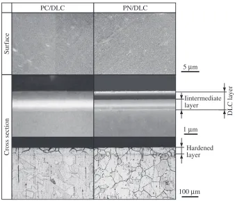
Figure 2 shows the features of the surface layer formed on PN/DLC material together with the microstructure observed on the cross section near the surface. Table 3 shows the fundamental characteristics of the DLC layer. Figure 3 shows the hardness distribution of PN/DLC material. For compar-ison, the above figures and table include the results of the previous study concerning PC/DLC material.13) In Fig. 2, although the DLC layers of PN/DLC and PC/DLC materials seem to be different, it resulted from the difference in resolving power of the SEMs used.
As shown in Fig. 2, almost no droplets and pits were found on the DLC layer of PN/DLC material. In this study, the DLC layer of PN/DLC material was observed by SEM φ11.5
5
140
φ
6
(a)
(b) φ11.5 R15
40 50
φ
6
(c) φ11.5
90
11
R30
[image:2.595.58.548.85.127.2]Fig. 1 Specimen shapes (mm): (a) button-type specimen, (b) tensile specimen (JIS Z 2201, No. 14), (c) fatigue specimen (JIS Z 2274, No. 2).
Table 2 Conditions of the ball-on-disc type friction test.
Material of balls Alumina (diameter 5 mm) Test force,Ft/N 9.8 (1 kg) Rotating diameter,dr/mm 3
Sliding speed,vs/mm s¹1 40
Circumstances No lubrication, room temperature Table 1 Chemical compositions of stainless steel SUS316 (mass%).
C Si Mn P S Ni Cr Mo Fe
[image:2.595.47.289.137.316.2] [image:2.595.307.549.172.244.2]possessing higher resolving power than in the previous study. Accordingly, the two layers were clearly distinguished in the surface layer: the outermost layer is the single DLC layer; the second layer is the intermediate layer for improving adhesion force through a gradual change in composition. Hereafter, the
above surface layer is called “DLC layer”, including the intermediate layer.
The DLC layer of PN/DLC material had almost the same thickness, hardness and Young’s modulus as the DLC layer of PC/DLC material (Table 3). In the case of PN/DLC material, however, the adhesion force of the DLC layer was higher. This resulted from the difference in the hardness under the DLC layers, as mentioned below.
Although plasma nitriding and plasma carburizing as pretreatments formed hardened layers with almost the same thickness under the DLC layers (Fig. 3), the hardness was greater in the case of plasma nitriding. This meant that the hardened layer which was formed by plasma nitriding strongly suppressed plastic deformation occurring below the DLC layer. As a result, the adhesion force of the DLC layer became higher in PN/DLC material.
3.2 Friction coefficient
Figure 4 shows the result of the friction test conducted on PN/DLC material. This figure includes the results of the previous study.13)
As shown in Fig. 4, the friction coefficient was greatly reduced by the hybrid surface treatments (PN/DLC, PC/ DLC). As mentioned in section 3.1, the thickness and hardness of the DLC layers formed on both materials were almost the same; however, the friction coefficient of PN/ DLC material was lower than that of PC/DLC material.
Although the DLC layers had marked hardness, plastic deformation was induced in the substrates under high contact force. If hardened layers are formed below the DLC layers, plastic deformation is suppressed and the surfaces can remain flat. In consequence, friction force resulting from surface roughness will reduce. This means that the increase in
1 μm PN/DLC
DLC layer
PC/DLC
Surf
ace
Cross section
5 μm
100 μm Hardened layer Iintermediate layer
[image:3.595.129.467.68.357.2]Fig. 2 Features of the DLC layers and the microstructures.
Table 3 Fundamental characteristics of the DLC layers.
Thickness,
tDLC/µm
Hardness,
H/GPa
Young’s modulus,
EDLC/GPa
Adhesion force,
Fa/N
PN/DLC 1.40 66.0 300 45
PC/DLC 1.61 59.5 299 20
100 300 500 700 900 1100
0 20 40 60 80 100
Micro-V
ick
ers hardness,
H
/ Hv
Distance from surface, ds / μm Non PN/DLC PC/DLC
[image:3.595.44.289.409.469.2] [image:3.595.60.277.415.684.2]hardness of the hardened layers effectively reduces the friction coefficient. Therefore, the friction coefficient of PN/ DLC material was markedly lower than that of PC/DLC material.
Since it is well known that DLC coating reduces the friction coefficient of metals, many studies have focused on improving the properties of the DLC layers; however, the obtained result showed the importance of pretreatment to decrease the friction coefficient.
[image:4.595.67.271.69.248.2]3.3 Mechanical properties
[image:4.595.44.550.325.442.2]Table 4 shows the mechanical properties of PN and PN/ DLC materials together with the grain sizes of the materials. The fatigue strengths shown in this table are referred to later. Figure 5 shows the features of the side surface and fracture surface of PN/DLC material. For comparison, the above table andfigure include the results of the previous study.13)
Table 4 Mechanical properties, grain size and fatigue strengths.
Mechanical properties
Grain size,
dg/µm
Fatigue strength, ·w/MPa Young’s
modulus,
E/GPa
Yield strength, ·y/MPa
Tensile strength,
·t/MPa
Elongation (%)
Reduction in area
(%)
Non 193 246 591 62 72 61 300
PN 194 232 568 64 73 52 450
PN/DLC 196 241 571 65 72 52 470
PC 187 229 591 62 71 65 410
PC/DLC 197 224 581 59 69 69 460
0 0.2 0.4 0.6 0.8
0 100 200 300 400 500
Friction coef
ficient
Sliding distance, d w / m PC/DLC
Non
PN/DLC
Fig. 4 Relationship between the sliding distance and the friction coefficient.
20 μm 20 μm 50 μm PN/DLC
Side surf
ace
Fracture surf
ace
T
ensile axis
PC/DLC
[image:4.595.149.449.484.771.2]The previous study showed that plasma carburizing and DLC coating had no influence on the microstructure of the substrate because the surface treatments were conducted at relatively low temperatures. In addition to this, the thicknesses of the formed layers were much thinner than the diameter of the tensile specimens, so the mechanical properties depended on the properties of the substrates. As a result, the mechanical properties of stainless steel were unaffected by the surface treatments (Table 4).
On the other hand, the grain sizes of the substrates in PN and PN/DLC materials were almost the same as those of Non, PC and PC/DLC materials, although the grain sizes were slightly smaller (Table 4). Consequently, no marked difference was found in the mechanical properties between PN and PN/DLC materials and the materials examined in the previous study (Non, PC and PC/DLC).
In the tensile test, the hardened layer of PN/DLC material could not follow the large plastic deformation of the substrate and it fractured into small pieces, as shown in Fig. 5. Fracture of the hardened layer was observed on PC/DLC material; however, it was more significant on PN/DLC material than PC/DLC material because of the difference in the hardness of the hardened layers. In spite of the fracture of the hardened layers, no exfoliation of the DLC layers was found in either material. This result showed that the DLC layers strongly adhered to the substrates.
Moreover, ductile features (dimples) were observed on the fracture surface of PN/DLC material, as well as PC/DLC material. Namely, no surface crack deeply propagated to the inside, although the hardened layers fractured.
[image:5.595.326.530.310.518.2]3.4 Fatigue properties
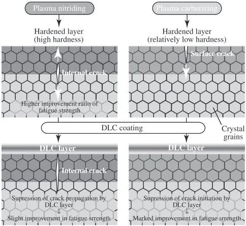
Figure 6 shows the S-N curves of PN and PN/DLC materials. Figure 7 shows their fatigue fracture surfaces observed near the crack initiation sites. To ease comparison, the fatigue strengths are listed in Table 4. The above figures include the results of the previous study.13) Furthermore, Fig. 8 shows a schematic illustration to explain the difference
in fatigue crack initiation and propagation between PN/DLC and PC/DLC materials.
The fatigue strength of Non material was 300 MPa (Fig. 6, solid triangle mark). As seen in Fig. 7, its fatigue crack initiated from the surface and propagated in a radial pattern to the inside. No non-propagating crack was found on the surfaces of the specimens survived without fracture by 107 cycles. This observation result showed that the resistance to crack initiation from the surface determined the fatigue strength of Non material.
In such cases, surface treatments are effective to improve the fatigue strength because formation of hardened layers directly increases resistance to crack initiation. In conse-quence, plasma nitriding (solid round mark) and plasma carburizing (solid squire mark) greatly improved the fatigue strength, as seen in Fig. 6.
Since plasma nitriding generated a hardened layer possess-ing greater hardness than plasma carburizpossess-ing (Fig. 3), crack
300 400 500 600
103 104 105 106 107
Maximum bending stress
,
σ a
/
MP
a
Cycles to failure Non PN PN/DLC PC PC/DLC
Fig. 6 S-N curves.
Non (σa=310MPa)
50 μm 50 μm
PC (σa=500MPa) PC/DLC (σa=470MPa)
PN (σa=460MPa) PN/DLC (σa=480MPa)
Arrows: crack inisiation sites
100 μm 100 μm 100 μm
[image:5.595.119.484.561.772.2]initiation from the surface was more strongly suppressed. As a result, plasma nitriding showed a higher improvement ratio of fatigue strength. Corresponding to this, the crack initiation site of PN material was located below the hardened layer while the fatigue crack of PC material initiated from the surface (Fig. 7). Especially in the case of PN material, a feature similar to a “fish-eye”, which is typical of internal crack initiation, was observed on the fracture surface.
DLC coating further improved the fatigue strength of PC material (Fig. 6, open squire mark) because the DLC layer directly suppressed crack initiation from the surface. On the other hand, since the fatigue crack of PN material initiated below the hardened layer, fatigue strength was mainly controlled by the resistance to crack initiation under the hardened layer even after DLC coating (open round mark).
Nevertheless, DLC coating slightly improved the fatigue strength of PN material. This result suggested that the DLC layer suppressed the crack propagation of internal cracks to the surface so that the fatigue life was elongated and contributed to the slight improvement in fatigue strength (Fig. 8). As mentioned above, crack initiation sites were closely related to the effect of DLC coating on the fatigue strength of plasma-treated materials.
4. Conclusion
(1) The DLC layers formed on PN and PC materials possessed almost the same characteristics; however, the adhesion force was higher in the case of the DLC layer formed on PN material.
(2) The friction coefficient of PN/DLC material was markedly lower than that of PC/DLC material. This result showed that pretreatment was important to decrease the friction coefficient of the DLC-coated material.
(3) The mechanical properties of stainless steel were unaffected by the hybrid surface treatments.
(4) Since plasma nitriding generated a hardened layer possessing higher hardness than plasma carburizing, its improvement ratio of fatigue strength was higher. DLC coating slightly improved the fatigue strength of PN material; however, its effect was more significant on PC materials because of the difference in the crack initiation sites.
Acknowledgement
This research was supported by the Japan Society for the Promotion of Science, Grant-in-Aid for Scientific Research (C), 20102012, No. 21560090 and 20132015, No. 24560098. The authors gratefully acknowledge the support.
REFERENCES
1) M. Takashima and N. Ohtake:J. Solid Mech. Mater. Eng. 5(2011) 938944.
2) M. Uchidate, H. Liu, A. Iwabuchi and K. Yamamoto:Wear263(2007) 13351340.
3) H. Ronkainen, S. Varjus and K. Holmberg:Wear249(2001) 267271.
4) H. Ronkainen, S. Varjus and K. Holmberg:Wear222(1998) 120128.
5) J. Robertson:Mater. Sci. Eng. R37(2002) 129281.
6) T. Horiuchi, K. Yoshida, M. Kano, M. Kumagai and T. Suzuki:
Tribology Online5(2010) 129135.
7) A. A. Voevodin, S. D. Walck and J. S. Zabinski:Wear203204(1997) 516527.
8) M. Ikeyama, S. Nakao, Y. Miyagawa and S. Miyagawa:Surf. Coat. Technol.191(2005) 3842.
9) K. I. Schiffmann:Surf. Coat. Technol.177178(2004) 453458.
10) C. J. Strondl, G. J. van der Kolk, T. Hurkmans, W. Fleisher, T. Trinh, N. M. Caravalho and J. Th. M. de Hosson:Surf. Coat. Technol.142 144(2001) 707713.
11) H. Dimigen, H. Hubsch and R. Memming:Appl. Phys. Lett.50(1987) 10561058.
12) N. Ueda, N. Yamauchi, T. Sone, A. Okamoto and M. Tsujikawa:Surf. Coat. Technol.201(2007) 54875492.
13) T. Morita, Y. Hirano, K. Asakura, T. Kumakiri, M. Ikenaga and C. Kagaya:Mater. Sci. Eng. A558(2012) 349355.
14) H. Akebono, M. Kato and A. Sugeta:Int. J. Mod. Phys. Conf. Ser.6
(2012) 312317.
15) T. Morita, Y. Hirano, K. Tomita, T. Kumakiri, C. Kagaya and M. Ikenaga: Trans. Japan Soc. Mech. Eng. A 75 (2009) 327332 (in Japanese).
16) T. Morita, K. Tomita, C. Kagaya, T. Kumakiri and M. Ikenaga:J. Solid Mech. Mater. Eng.2(2008) 645653.
17) H. Akebono and H. Suzuki:J. Solid Mech. Mater. Eng.2(2008) 1470 1477.
18) T. Morita, Y. Hirano, K. Tomita, T. Kumakiri, C. Kagaya and M. Ikenaga: Trans. Japan Soc. Mech. Eng. A 74 (2008) 693699 (in Japanese).
19) M. Hagarova, O. Blahovd and J. Savkova: Acta Metall. Slovaca15
(2009) 221227.
20) M. Hagarova: J. Met. Mater. Miner.17(2007) 2935.
21) I. Lagnado and S. M. Polcari:Solid-State Electron.10(1967) 1219 1220.
22) W. C. Oliver and G. M. Pharr:J. Mater. Res.7(1992) 15641583.
23) G. M. Pharr:Mater. Sci. Eng. A253(1998) 151159.
24) P. A. Steinmann, Y. Tardy and H. E. Hintermann: Thin Solid Films
154(1987) 333349.
25) K. Laugier:Thin Solid Films76(1981) 289294.
Τι−6Αλ−4ς Αλλοψ DLC layer
Τι−6Αλ−4ς Αλλοψ
Τι−6Αλ−4ς Αλλοψ DLC layer
Τι−6Αλ−4ς Αλλοψ
Hardened layer (relatively low hardness) Hardened layer
(high hardness)
Plasma carburizing Plasma nitriding
DLC coating
Surface crack
Internal crack
Internal crack Higher improvement ratio of
fatigue strength
Supression of crack propagation by DLC layer
↓
Slight improvement in fatigue srrength
Supression of crack initiation by DLC layer
↓
Marked improvement in fatigue srrength
Crystal grains
[image:6.595.48.290.70.292.2]