Effect of Hybrid Surface Treatment Composed of Plasma Nitriding
and Fine Particle Bombarding on Fatigue Strength of Ti
6Al
4V Alloy
Tatsuro Morita
1,+, Noriaki Uehigashi
2and Chuji Kagaya
31Department of Mechanical and System Engineering, Graduate School of Science and Technology,
Kyoto Institute of Technology, Kyoto 606-8585, Japan
2Compressor Division, Toyota Industries Corporation, Aichi 448-8671, Japan
3Department of Mechanical Engineering, Faculty of Engineering, Chubu University, Kasugai 487-8501, Japan
This study investigated the effect of hybrid surface treatment on the fatigue strength of Ti6Al4V alloy. The hybrid surface treatment was composed of plasma nitriding andfine particle bombarding (FPB). Plasma nitriding generated a hardened layer with no marked growth of the microstructure of the substrate, and subsequent FPB eliminated a compound layer formed outermost through plasma nitriding. Tensile strength was maintained at the initial level, although ductility was somewhat reduced by fracture of the hardened layer. Plasma nitriding decreased the fatigue strength because the brittle compound layer fractured at relatively low stress amplitude and hastened the propagation of cracks. On the other hand, the effect of the hardened layer appeared through the elimination of the compound layer, so that hybrid surface treatment greatly improved the fatigue strength. Correspondingly, a crack initiation site was found beneath the hardened layer and suggested that the formed layer strongly suppressed crack initiation from the surface. [doi:10.2320/matertrans.M2012262]
(Received July 26, 2012; Accepted October 2, 2012; Published November 16, 2012)
Keywords: titanium alloy, titanium6aluminum4vanadium, hybrid surface treatment, plasma nitriding,fine particle bombarding, compound layer, hardened layer, microstructure, mechanical properties, fatigue strength
1. Introduction
Ti6Al4V alloy is a typical ¡+¢ titanium alloy possessing high specific strength and excellent corrosion resistance. This alloy is widely used in the aerospace industry and occupies more than 50% of the titanium market in the USA.1) Accordingly, improvement of its functionality and strength will have a great impact on various products.
On the other hand, titanium has inherent problems such as a high friction coefficient and low wear resistance. To overcome these problems, various surface treatments have been investigated. For example, nitriding generates a hard-ened layer and greatly improves the friction-wear character-istics of titanium;28) however, many studies have reported that nitriding strikingly reduces its fatigue strength.813)
According to our studies,1215)the reduction in the fatigue strength of titanium by nitriding resulted from significant growth of the microstructure and formation of a brittle compound layer. In particular, since Young’s modulus of the compound layer was markedly higher than that of the substrate, high stress was applied to the compound layer and facilitated its fracture. Thefirst cause, that is, the growth of the microstructure, can be prevented by conducting plasma treatments at a relatively low temperature; however, the second cause relating to the compound layer is unavoidable, except for its elimination.
Against the above background, the previous study investigated the effect of hybrid surface treatment on the fatigue strength of Ti6Al4V alloy.16,17)The hybrid surface treatment was composed of plasma carburizing and fine particle bombarding (FPB). Plasma carburizing generated a hardened layer. The subsequent FPB eliminated the com-pound layer, and introduced high compressive residual stress. The results showed that the formed layer was greatly effective
to improve the fatigue strength. Tsujiet al.also reported that the combination of plasma carburizing and deep rolling gave a similar effect to the fatigue strength of Ti6Al4V alloy.18) In the above hybrid surface treatment, plasma carburizing was selected because there was a fear from the past studies that plasma nitriding might reduce fatigue strength. On the other hand, since plasma nitriding generates a hardened layer possessing high hardness, a better effect than plasma carburizing was expected. Based on this prediction, this study further investigated the effect of hybrid surface treatment composed of plasma nitriding and FPB on the fatigue strength of Ti6Al4V alloy. In particular, crack initiation sites were carefully observed on fatigue fracture surfaces.
2. Materials and Experimental Procedures
2.1 Materials and treatment conditions
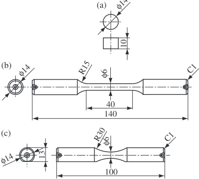
Table 1 shows the chemical composition of Ti6Al4V alloy used in this study. The material was supplied as round bars (diameter 14 mm) and machined to three specimen shapes, shown in Fig. 1. The test sections (flat surface part) of button specimens were polished to mirror surfaces with emery papers and alumina powders. The test sections of tensile and fatigue specimens were polished with emery papers and finally electro-polished using a mixture of acetic anhydride and perchloric acid.
To obtain basic data, plasma nitriding was performed at 973, 1023, 1073 and 1123 K for 14.4 ks (4 h). For comparison, untreated material was prepared. Hereafter, these materials are called “PN973PN1123”and “Non”materials, respectively.
Table 1 Chemical composition of Ti6Al4V alloy used in this study (mass%).
Al V O Fe H C N Ti
5.80 3.70 0.190 0.210 0.0028 0.001 0.010 Bal. +Corresponding author, E-mail: morita@kit.ac.jp
In addition, PN1123 material possessing the thickest hardened layer in this study was used to investigate the effect of FPB. Table 2 shows the conditions of FPB. In this table, FPB1 was conducted to eliminate the compound layer using squarish SiC particles. FPB2 was composed of the following three steps: The compound layer was firstly eliminated by FPB1, and then introduction of compressive residual stress was attempted by high speed steel particles. Thefinal step was carried out to eliminate ferrous element diffused on the surface and reduce surface roughness, using alumina particles. Hereafter, these FPBed materials are called“PN1123/FPB1” and“PN1123/FPB2”materials, respectively.
2.2 Experimental procedures
The cross sections of button specimens were polished to mirror surfaces and etched by a water-diluted mixture of hydrofluoric acid and nitric acid. Then, the microstructures near the surfaces were optically observed.
For hardness measurements, a micro-Vickers hardness tester with a CCD camera was used. The surface hardness was measured five times on the test sections of button specimens under test force of 245 mN (25 gf ), and the averages were used as data. Since the test sections of PN1123/FPB1 and PN1123/FPB2 materials were slightly rough, appropriate square-shaped indentations were selected from many indentations. The hardness distributions were obtained on the cross sections under the same test force. The hardness measurement was carried out five times at each position, and their averages were used as data.
X-ray diffraction was conducted on the test sections of button specimens under the following conditions: X-ray tube: Cu (K¡ ray), scanning speed: 0.02°/s, scanning step: 0.01°. X-ray residual stress measurement was performed on the test sections of fatigue specimens in the axis direction. The measurement conditions were as follows: X-ray tube: Cu (K¡ ray), diffraction angle: 2ª=148.4°, diffraction plane: (302),
¼ angel: ¼=10, 20, 30, 35, 40°, oscillation: «3°, stress constant:K=¹211.8 MPa. In addition, the center of gravity
method was used for peak search.
The tensile test was conducted in air at room temperature for three specimens of each material, based on JIS Z 2241, and the average values were used as data. The side surfaces and fracture surfaces were observed by scanning electron microscopy (SEM). The plane-bending fatigue test was performed in air at room temperature, based on JIS Z 2275. The cyclic speed was 33 Hz and stress ratio was R=¹1.
The crack initiation sites were observed on the fatigue fracture surfaces by SEM.
3. Results and Discussions
3.1 Plasma nitriding
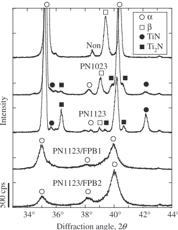
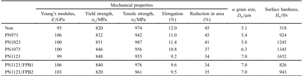
Figure 2 shows the microstructures observed near the surfaces of all materials. Figure 3 shows the results of X-ray diffraction, and Fig. 4 shows the hardness distributions. Table 3 shows the mechanical properties, ¡ grain size and surface hardness of each material. In addition, although the above figures and table include the results of the hybrid surface-treated materials (PN1123/FPB1, PN1123/FPB2), they are referred to later.
As shown in Fig. 2(b), plasma nitriding generated two different layers. The detailed studies of plasma nitriding19,20) reported that the outermost thin layer was the compound layer composed of TiN and Ti2N. The peaks corresponding to these compounds were identified in the X-ray profile of the PN1023 and PN1123 materials (Fig. 3). According to the same references, the second layer below the compound layer was an¡layer formed by diffusion of nitrogen, which is an¡ stabilizer. Since the amount of diffused nitrogen increased with increasing treatment temperature, the compound layer and ¡layer became thicker.
At the same time, plasma nitriding generated a hardened layer because of solid solution hardening by diffusion of nitrogen. As understood from Fig. 4, its thickness increased with increasing treatment temperature. Although the surface hardness also increased (Table 3), this was mainly attributed to the increase in the thickness of the compound layer. Namely, the used test force was relatively high, so that the surface hardness was thought to depend on its thickness.
The mechanical properties of all materials shown in Table 3 are arranged in Fig. 5 to ease comparison. Figure 6 shows the features of side surfaces together with fracture surfaces.
As shown in Fig. 2 and Table 3 (¡grain size), although the microstructure of the substrate grew slightly with increasing treatment temperature of plasma nitriding, it was insignif-icant. Further, the hardened layers were very thin compared to the specimen diameter. As a result, the Young’s modulus and static strengths were almost unaffected by plasma
φ14
10
140
φ
6
φ14
100
φ
6
13
R30 R15
(a)
(b)
(c)
C1
φ14 C1
40
[image:2.595.68.271.76.259.2]Fig. 1 Configurations of specimens (mm): (a) button specimen; (b) tensile specimen (JIS Z 2241, No. 14); (c) fatigue specimen (JIS Z 2274, No. 2).
Table 2 Treatment conditions of FPB.
Particle
Maximum diameter,
d/µm
Air pressure,
p/Pa
Treatment time,
t/s
FPB1 SiC 75 0.3 10 each
(button specimen) 30 each (tensile and fatigue
sepcimens) FPB2
SiC 75 0.3
High speed steel 69 0.6
[image:2.595.46.289.328.415.2]PN1123/FPB1 PN1123/FPB2
Non PN973 PN1023
PN1073 PN1123
10 μm Compound layer α phase
α+β phase Compound layer
α phase
α+β phase Hv
Hardness distribution
Hardened layer
α phase
α+β phase
10 μm
(a)
(b)
(c)
Fig. 2 Microstructures observed near the surfaces on the cross sections: (a) schematic illustration; (b) plasma-nitrided materials; (c) hybrid surface-treated materials.
34° 36° 38° 40° 42° 44°
Diffraction angle, 2θ
Intensity
500 cps
α β TiN
Ti2N
Non
PN1123
PN1123/FPB1
PN1123/FPB2 PN1023
Fig. 3 X-ray diffraction profiles.
300 400 500 600
0 20 40 60 80 100 120 140
Micro-V
ick
ers hardness,
H
/ Hv
Distance from surface, d
s / μm
Non PN 973 PN1023 PN1073 PN1123 PN1123/FPB1 PN1123/FPB2
[image:3.595.134.461.64.484.2] [image:3.595.79.260.535.769.2] [image:3.595.320.530.561.767.2]nitriding because they were closely related to the properties of the substrate (Fig. 5).
On the other hand, the hardened layer could not follow the large plastic deformation of the substrate, so that it fractured during the tensile test, as seen in Fig. 6. When the thickness of the hardened layer increased, cracks became large and reached a deep position. Accordingly, the elongation and the reduction in area decreased with increasing treatment temperature (Fig. 6); however, the fracture surfaces observed near the center of specimens exhibited ductile features possessing dimples.
3.2 Hybrid surface treatment
As mentioned in the previous section, the X-ray profile of PN1123 material showed the peaks of TiN and Ti2N (Fig. 3). These peaks disappeared in the profiles of PN1123/FPB1 and PN1123/FPB2 materials. The above results meant that FPB completely eliminated the compound layer formed on PN1123 material.
Since FPB eliminated the surface beyond the compound layer, the¡layer became slightly thinner, as seen in Fig. 2(c); however, the surface hardness of PN1123/FPB1 and PN1123/FPB2 materials was relatively high (Table 3), and their hardness distributions were almost the same as for PN1123 (Fig. 4). Moreover, the mechanical properties of PN1123 material were almost unaffected by FPB1 and FPB2, as shown in Fig. 5.
3.3 Effect of hybrid surface treatment on fatigue strength
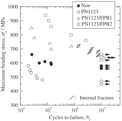
Figure 7 shows the SN curves and Fig. 8 shows the features of fatigue fracture surfaces observed near the initiation sites of cracks. To ease comparison, Table 4 shows
the surface hardness, residual stress and fatigue strength of each material together.
As understood in Fig. 7, the fatigue strength of PN1123 material ( ) markedly decreased from that of the Non material ( ). The fracture surface of Non material showed that a fatigue crack initiated from the surface and propagated in a radial pattern to the inside (Fig. 8). In the case of PN1123 material, however, the fracture surface revealed that a crack initiated in the compound layer and propagated along it. This difference meant that the brittle compound layer hastened the initiation and propagation of cracks and reduced fatigue strength.1215)
On the other hand, the fatigue strengths of PN1123/FPB1 ( ) and PN1123/FPB2 materials ( ) improved beyond Non material (Fig. 7). If the stress amplitude was relatively high, the fatigue cracks of PN1123/FPB1 and PN1123/FPB2 materials initiated from the surfaces, as seen in Fig. 8; however, when the stress amplitude was near the fatigue strengths, cracks were formed under the hardened layers. Especially in the case of PN1123/FPB2 material, afish-eye like feature was observed at the crack initiation site on the fracture surface. This result clearly showed that the effect of the hardened layer appeared through elimination of the compound layer. Namely, since the formed layer strongly suppressed crack initiation from the surface, hybrid surface treatment improved fatigue strength.
The fatigue strength of PN1123/FPB2 material was somewhat higher than that of PN1123/FPB1 material. This mainly resulted from the difference in surface hardness because the compressive residual stresses of both materials were low (Table 4); that is, the propagation of internal cracks to the surface was more suppressed in PN1123/FPB2 possessing high surface hardness.
[image:4.595.45.550.84.212.2]As reported in the previous study,21)FPB greatly improved the fatigue strength of commercial pure titanium. The results showed that the improvement effect was closely related to the surface characteristics because the formed surface layer acted as a barrier to suppress the propagation of internal cracks. The results obtained in this study meant that FPB possessed the same effect on the fatigue strength of plasma-nitrided titanium alloy in addition to the elimination of the compound layer. Moreover, the surface characteristics directly affected fatigue life when fatigue cracks initiated from the surface. As a result, the fatigue life of PN1123/FPB2 material was much longer than that of PN1123/FPB1 material (Fig. 7). Table 3 Mechanical properties,¡grain size and surface hardness.
Mechanical properties
¡grain size,
D¡/µm
Surface hardness,
Hs/Hv
Young’s modulus,
E/GPa
Yield strength, ·y/MPa
Tensile strength, ·t/MPa
Elongation (%)
Reduction in area (%)
Non 95 820 974 12.0 45 5.1 318
PN973 106 832 942 11.0 45 5.4 924
PN1023 100 851 987 11.4 41 5.8 1245
PN1073 100 846 956 10.8 37 6.3 1345
PN1123 99 848 955 9.2 34 7.0 1652
PN1123/FPB1 106 840 976 9.6 34 7.0 826
PN1123/FPB2 103 820 961 9.5 35 7.0 943
Young's modulus 0 20 40 60 80 100 120
Non PN973 PN1023 PN1073 PN1123 PN1123/FPB1 PN1123/FPB2
Normalized ratio (%)
Yield
strength Elongation Tensile
strength
Reduction in area
[image:4.595.51.290.252.351.2]As mentioned above, hybrid surface treatment achieved the initial purpose of generating a hardened layer and improving fatigue strength at the same time. Concerning fatigue strength, the results gave the following three important findings that should be considered for this treatment: (1) No high compressive residual stress was introduced even by FPB2 to PN1123 material possessing a thick hardened layer, because plastic deformation was restricted. This suggested that a relatively thin hardened
layer would be suitable for further improvement of fatigue strength; (2) The formation of subsurface cracks meant that strengthening of the substrate would further improve the bending fatigue strength; (3) More detailed investigation of the surface microstructure is needed because it closely related to the fatigue properties of hybrid surface-treated material.
4. Conclusion
This study investigated the effect of hybrid surface treatment composed of plasma nitriding and FPB on the fatigue strength of Ti6Al4V alloy. The obtained results are as follows:
(1) Plasma nitriding generated a compound layer. At the same time, a hardened layer formed due to solid solution hardening of nitrogen. Although the brittle compound layer was eliminated by subsequent fine particle bombarding (FPB), the hardness distribution was almost unchanged.
PN1123/FPB1 PN1123/FPB2
Non PN973 PN1023
PN1123
PN1073
100 μm
20 μm
Side surf
ace
Fracture surf
ace
Side surf
ace
Fracture surf
ace
T
ensile axis
Fig. 6 Features of the side surfaces and the tensile fracture surfaces.
300 400 500 600 700 800 900 1000
104 105 106 107
Maximum bending stress,
σ a
/ MP
a
Cycles to failure, Nf
Internal fracture Non
PN1123 PN1123/FPB1 PN1123/FPB2
[image:5.595.95.502.67.401.2]Fig. 7 SN curves.
Table 4 Surface hardness, residual stress and fatigue strength.
Surface hardness,
Hs/Hv
Residual stress, ·r/MPa
Fatigue strength ·w/MPa
Non 318 ¹27«7 570
PN1123 1652 ® 470
PN1123/FPB1 826 ¹63«13 640
[image:5.595.67.274.432.638.2] [image:5.595.303.550.447.522.2](2) The static strength was unaffected by plasma nitriding conducted under the examined treatment conditions, because no marked growth of the microstructure of the substrate occurred; however, the ductility somewhat decreased when a thick hardened layer was generated. Moreover, the mechanical properties of the plasma-nitrided material were unaffected by FPB.
(4) Plasma nitriding strikingly reduced fatigue strength due to the formation of the compound layer. Elimination of this layer by FPB greatly improved fatigue strength. (5) The best result obtained in this study was achieved by the combination of plasma nitriding at 1123 K for 14.4 ks (4 h) with the subsequent FPB2 (Table 2). Concretely, the surface hardness was 943 Hv, the thickness of the hardened layer was 110 µm and the improvement ratio of the fatigue strength reached 16%.
Acknowledgments
The authors gratefully thank Tanaka Inc. for plasma nitriding and Fujikihan Co. Ltd. for FPB.
REFERENCES
1) G. Lutjering and J. C. Williams: Titanium, (Springer-Verlag, Berlin, 2003) p. 7.
2) R. W. Hanzel: Metal Progress, March (1954) 8996.
3) J. R. Cuthill, W. D. Hayes and R. E. Seebold:J. Res. Natl. Bur. Stand. A Phys. Chem.64A(1960) 119125.
4) K. N. Strafford and J. M. Towell:Oxid. Metals10(1976) 4167.
5) E. Rolinski:Mater. Sci. Eng. A108(1989) 3744.
6) M. Salehi, T. Bell and P. H. Morton: Surface Modification Technology IV, (The Minerals, Metals and Materials Society, 1991) pp. 9911002. 7) Y. S. Hu, D. H. Dai and Y. L. Dong: Proc. 6th World Conference of
Titanium (France), (1988) pp. 18011804.
8) E. Mitchell and P. J. Brotherton: J. Inst. Met.93(196465) 381386. 9) T. Bell, H. W. Bergmann, J. Lanagan, P. H. Morton and A. M. Staines:
Surf. Eng.2(1986) 133143.
10) J. Lanagan: Proc. 6th World Conference of Titanium (France), (1988) pp. 19571962.
11) K. Tokaji, T. Ogawa, H. Shibata and Y. Kamiya:Trans. Japan Soc. Mech. Eng. A57(1991) 22932299 (in Japanese).
12) T. Morita, H. Takahashi, M. Shimizu and K. Kawasaki:Fatigue Fract. Eng. Mater. Struct.20(1997) 8592.
13) T. Morita, S. Fuchikawa, J. Komotori, M. Shimizu, K. Minakawa and K. Kawasaki: Ti-2003 Science and Technology, II, (2004) pp. 941 948.
14) T. Morita, K. Saito and M. Shimizu: Theor. Appl. Mech. Japan 44
(1995) 137144.
15) T. Morita and Y. Tanaka: Theor. Appl. Mech. Japan53(2004) 1926. 16) T. Morita, T. Ohtomo, C. Kagaya, S. Tanaka and N. Tsuji: J. Soc.
Mater. Sci. Japan56(2007) 872879 (in Japanese).
17) T. Morita, T. Ohtomo, C. Kagaya, S. Tanaka and N. Tsuji: J. Soc. Mater. Sci. Japan57(2008) 838845 (in Japanese).
18) N. Tsuji, S. Tanaka and T. Takasugi:Mater. Sci. Eng. A499(2009) 482488.
19) H. J. Brading, P. H. Morton and T. Bell:Nucl. Instrum. Methods Phys. Res. B66(1992) 230236.
20) E. S. Metin, A. D. Romig, O. T. Inal and E. Semarge: Microbeam Analysis, ed. by D. E. Newbury, (San Francisco Press, 1988) pp. 498 502.
21) T. Morita, H. Nakaguchi, S. Noda and C. Kagaya:Mater. Trans.53
(2012) 19381945.
50 μm
500 μm
50 μm
500 μm
PN1123/FPB1 PN1123/FPB2
High magnif
ication
Lo
w magnif
ication
High magnif
ication
Lo
w magnif
ication
PN1123 Non
a= 600 MPa
Nf = 5.0×10⁴ Na = 480 MPa
f = 6.5×10⁴
a = 680 MPa
Nf= 3.7×10⁶
a= 850 MPa
Nf = 2.6×10⁴
a = 700 MPa
Nf = 4.4×10⁶
a = 860 MPa
Nf = 1.4×10⁵
Crack propagation Crack propagation
Crack initiation site Vicinity of crack initiation site
Crack initiation site Crack initiation site Crack initiation site
Crack initiation site
σ σ σ
σ σ
σ
[image:6.595.97.497.68.385.2]