University of Warwick institutional repository: http://go.warwick.ac.uk/wrap
A Thesis Submitted for the Degree of PhD at the University of Warwick
http://go.warwick.ac.uk/wrap/66981
This thesis is made available online and is protected by original copyright. Please scroll down to view the document itself.
M A
E
G
NS I
T A T MOLEM
U N
IV
ER
SITAS WARWICEN SIS
Performance Analysis for
Cooperative Wireless
Communications
by
Kezhi Wang
Thesis
Submitted to University of Warwick in partial
fulfilment of the requirements for the degree of
Doctor of Philosophy
School of Engineering
Contents
Acknowledgments vii
Declarations ix
Abstract x
List of Publications xii
List of Figures xiv
List of Tables xviii
Abbreviations xix
Important Symbols xxii
Chapter 1 Introduction 1
1.1 Wireless Communications . . . 1
1.2 Evolution of Mobile Communication Systems . . . 2
1.3 Cooperative Wireless Communications . . . 5
1.4 Thesis Outline . . . 9
1.4.2 Chapter Outlines . . . 11
Chapter 2 Background 14 2.1 Channel Models . . . 14
2.1.1 AWGN . . . 14
2.1.2 Rayleigh Fading Channels . . . 16
2.1.3 Ricean Fading Channels . . . 17
2.1.4 Nakagami-m Fading Channels . . . 17
2.1.5 α -µ Fading Channels . . . 18
2.1.6 Characteristics of Fading Channels . . . 19
2.2 Modulation Scheme . . . 20
2.2.1 Binary Phase Shift Keying . . . 21
2.2.2 Higher Order Modulations . . . 24
2.3 Cooperative Wireless Relaying . . . 24
2.3.1 Cooperative Techniques and Performance Analysis . . . 26
2.3.2 Cooperative Relaying . . . 29
2.3.3 Relay Combining . . . 30
2.4 Decision Fusion . . . 33
2.5 System Performance Measures . . . 35
2.5.1 Signal-to-Noise Ratio . . . 36
2.5.2 Outage Probability . . . 36
2.5.3 Bit Error Rate . . . 37
2.6 Related Methods . . . 38
2.6.1 Moment Generating Function . . . 38
2.6.2 Characteristic Function . . . 39
Chapter 3 Performance Analysis and Optimal Energy
Alloca-tion for Amplify-and-Forward Relaying
Using Pilot-Aided Maximum Likelihood Estimation 43
3.1 Introduction . . . 43
3.2 System Model . . . 48
3.3 Pilot-Aided Maximum Likelihood Estimation . . . 52
3.3.1 Disintegrated Channel Estimation . . . 52
3.3.2 Cascaded Channel Estimation . . . 53
3.4 BER and Optimal Energy Allocation in Disintegrated Channel Estimation . . . 55
3.4.1 Estimation of CSI at the Relay . . . 55
3.4.2 Estimation of CSI at Both the Relay and Destination . 58 3.5 BER and Optimal Energy Allocation in Cascaded Channel Estimation . . . 63
3.5.1 Using Gdf ix1 and Gwf ix1 . . . 64
3.5.2 Using Gdf ix2 and Gwf ix2 . . . 67
3.6 Numerical Results and Discussion . . . 70
3.6.1 Validation of BER Expressions . . . 71
3.6.2 Optimal Energy Allocation Evaluation . . . 77
3.7 Conclusions . . . 83
Chapter 4 Performance Analysis for Amplify-and-Forward Re-laying with Randomly Distributed and Fixed Interferers 87 4.1 Introduction . . . 87
4.2 System Model . . . 90
4.3.1 PDF of Ysj and Yjd . . . 95
4.3.2 PDF and CDF of Γsj and Γjd . . . 97
4.3.3 Outage Probability . . . 100
4.3.4 Special Cases . . . 103
4.4 Fixed Interferers . . . 104
4.4.1 PDF and CDF of Γsj and Γjd . . . 104
4.4.2 Outage Probability . . . 107
4.4.3 Dominant Interferences . . . 108
4.4.4 I.i.d. Interferences . . . 108
4.4.5 Rayleigh Fading Signal . . . 111
4.5 Numerical Results and Discussion . . . 112
4.6 Conclusions . . . 126
Chapter 5 Performance Analysis for Multihop Relaying and Multiple Scattering over α - µ Fading Channels 127 5.1 Introduction . . . 127
5.2 System Model . . . 130
5.2.1 Sum of Ratios of Products of α -µ RVs . . . 131
5.2.2 Sum of Products of α -µ RVs . . . 131
5.2.3 Ratio of Sums of Products of α -µ RVs . . . 132
5.3 Exact Results . . . 132
5.3.1 MGF . . . 133
5.3.2 PDF and CDF . . . 135
5.4 Approximate Results . . . 136
5.4.1 Approximate PDF and CDF . . . 137
5.4.3 Moment-Matching Approximations . . . 141
5.5 Applications . . . 145
5.6 Numerical Results and Discussion . . . 149
5.7 Conclusions . . . 157
Chapter 6 Performance Analysis for Hard-Decision Fusion with Arbitrary Numbers of Bits for Different Samples 159 6.1 Introduction . . . 159
6.2 System Model and Technical Background . . . 162
6.2.1 System Model . . . 162
6.2.2 Technical Background . . . 163
6.3 Optimal Hard-Decision Fusion Rule . . . 164
6.4 BER of Decision Fusion with 1 Bit . . . 167
6.5 Numerical Results and Discussion . . . 168
6.5.1 Best Thresholds and BERs Assuming a Perfect Control Channel . . . 169
6.5.2 Simulation of Arbitrary Bits Decision Fusion Rule . . . 174
6.6 Conclusions . . . 179
Chapter 7 Conclusions and Future Work 180 7.1 Conclusions . . . 180
7.2 Future Work . . . 183
A.3 Derivation of the Second BER Approximation for the First Case
in DCE . . . 187
A.4 Derivation of Outage Probability for the Second Case in DCE 188
A.5 Derivation of Outage Probability for CCE . . . 188
Appendix B Derivation for Random Interferers and Fixed
Inter-ferers 189
B.1 Derivation of PDF of Ysj for Random Interferers . . . 189
B.2 Derivation of PDF of Γsj for Random Interferers . . . 191
B.3 Derivation of CDF of Γsj for Random Interferers . . . 192
B.4 Derivation of the High SINR Approximations for PDF and CDF
of Γsj for Random Interferers . . . 194
B.5 Derivation of PDF and CDF of Γjd for Random Interferers . . 195
B.6 Derivation of PDF and CDF of Γsj for Fixed Interferers . . . . 196
B.7 Derivation of PDF and CDF of Γjd for Fixed Interferers . . . . 197
B.8 Derivation of CDF of Γj for the Dominant Fixed Interferences 199
Appendix C Derivation for α-µ RVs 200
C.1 Derivation of MGF for Sum of Ratios of Products ofα-µ RVs 200
C.2 Derivation of GGRA and GRA Approximation . . . 202
Appendix D Derivation for Hard-Decision Fusion Rule 204
D.1 Derivation of the Characteristic Function of Hard-Decision
Fu-sion with 1 Bit for BPSK . . . 204
Acknowledgments
First and foremost, I would like to express my greatest gratitude to my
super-visor, Dr. Yunfei Chen from the School of Engineering at University of
War-wick for his careful supervision, constructive suggestions and valuable time.
It would simply not have been possible to produce this work without his
pa-tient guidance, inspiration, encouragement and warm support. It is my very
great privilege to have been his student. Also, I would like to thank him for
supporting me to attend the international conference in Canada.
My special thanks also goes to Warwick Graduate School for awarding
me Chancellor’s International Scholarship, which has been making my study
in U.K. come true. Without this scholarship, I would not have come and been
studying here and achieved this point.
I also would like to take this opportunity to express my appreciations
to Climate-KIC and European Institute of Innovation and Technology (EIT)
for supporting me to attend summer school in Netherlands and Germany and
then supporting me to attend conferences in Poland and Hungary. I have
learned a lot from these training courses.
More importantly, I would like to thank my beloved parents for their
unconditional sacrifices, constant encouragement, continuous support and
end-less love. They always have faith in me and are proud of me. I would like to
dedicate this thesis to them.
War-wick. I would like to thank her for the companionship during the happy and
hard time.
Last but not the least, I was very lucky to have met so many good friends
in U.K., especially the members from Communications Systems Laboratory
Declarations
This thesis is submitted in partial fulfillment for the degree of Doctor of
Philos-ophy under the regulations set out by the Graduate School at the University of
Warwick. This thesis is solely composed of research completed by Kezhi Wang,
except where stated, under the supervision of Dr. Yunfei Chen between the
dates of October 2011 and October 2014. This thesis has not previously been
presented in identical or similar form to any other examination board.
Kezhi Wang
Abstract
Cooperative relaying has been proposed as a promising solution to mitigate
and combat the deleterious effects of fading by sending and receiving
inde-pendent copies of the same signal at different nodes. It has attracted huge
attention from both industry and academia. The purpose of this thesis is
to provide an analytical performance evaluation of the cooperative wireless
systems while taking some realistic conditions into consideration.
To achieve this, first, performance analysis of amplify-and-forward (AF)
relaying using pilot-aided maximum likelihood estimation is studied in this
thesis. Both disintegrated channel estimation (DCE) and cascaded channel
estimation (CCE) are considered. Based on this analysis, optimal energy
al-location is proposed.
Then, performance analysis for AF relaying corrupted by interferers are
investigated. Both randomly distributed and fixed interferers are considered.
For random interferers, both the number and the locations of the interferers
are random while for fixed interferers, both the number and the locations are
fixed.
Next, multihop relaying and multiple scattering channels over α - µ
fading are analyzed. Channels with interferences and without interferences are
considered. Exact results in the form of one-dimensional integral are derived.
Also, approximate results with simplified structure and closed-form expressions
Finally, a new hard decision fusion rule that combines arbitrary numbers
of bits for different samples taken at different nodes is proposed. The best
thresholds for the fusion rules using 2 bits, 3 bits and 4 bits are obtained
through simulation. The bit error rate (BER) for hard fusion rule with 1 bit
is provided.
Numerical results are presented to show the accuracy of our analysis and
provide insights. First, they show that our optimal energy allocation methods
outperform the conventional system without optimal energy allocation, which
could be as large as several dB’s in some cases. Second, with the increase
of signal-to-interference-plus-noise ratio (SINR) for AF relaying with
interfer-ence, the outage probability decreases accordingly for both random and fixed
interferers. However, with the change of interference-to-noise ratio (INR) but
with the SINR fixed, the outage probability for random interferers change
cor-respondingly while the outage probability for fixed interferers remains almost
the same. Third, our newly derived approximate expressions are shown to
have acceptable performances in approximating outage probability in wireless
multihop relaying system and multiple scattering channel considering
inter-ferences and without interinter-ferences. Last, our new hard decision fusion rule is
shown to achieve better performance with higher energy efficiency. Also they
show that there is a tradeoff between performance and energy penalty in the
List of Publications
Journal Papers
• Kezhi Wang, Yunfei Chen, Mohamed-Slim Alouini, Xu Feng, “BER
and Optimal Power Allocation for Amplify-and-Forward Relaying Using
Pilot-Aided Maximum Likelihood Estimation”, IEEE Transactions on Communications, (DOI: 10.1109/TCOMM.2014.2358219).
• Kezhi Wang, Yunfei Chen, Marco Di Renzo, “Outage Probability of
Dual-Hop Selective AF With Randomly Distributed and Fixed
Interfer-ers”, IEEE Transactions on Vehicular Technology, (DOI: 10.1109/TVT.2014.2366727).
• Kezhi Wang, Tian Wang, Yunfei Chen, Mohamed-Slim Alouini,
“Statistics ofα-µRandom Variables and Their Applications in Wireless
Multihop Relaying and Multiple Scattering Channels”, IEEE Transac-tions on Vehicular Technology, (DOI: 10.1109/TVT.2014.
2345258).
• Yunfei Chen, Kezhi Wang, Jiming Chen, “Hard-Decision Fusion With
• Kezhi Wang, Yunfei Chen, Jiming Chen, “ALRT-Based Energy
Detec-tion Using Uniform Noise DistribuDetec-tion”, Wireless Communications and Mobile Computing, (second round of reviewing).
Conference Papers
• Kezhi Wang, Tian Wang, Yunfei Chen, Mohamed-Slim Alouini, “Sum
of Ratios of Products for α -µ Random Variables in Wireless Multihop
Relaying and Multiple Scattering”, in IEEE 80th Vehicular Technology Conference (VTC2014-Fall), Vancouver, Canada, Sep. 2014.
• Kezhi Wang, Yunfei Chen, Mohamed-Slim Alouini, Feng Xu,
“Pi-lot Power Optimization for AF Relaying Using Maximum Likelihood
List of Figures
2.1 Constellation diagram for BPSK and QPSK . . . 21
2.2 Decision regions . . . 22
2.3 A typical cooperative wireless communication system with a
cooperative diversity link. . . 25
2.4 Cooperative wireless relaying in LTE-Advanced standard. . . . 26
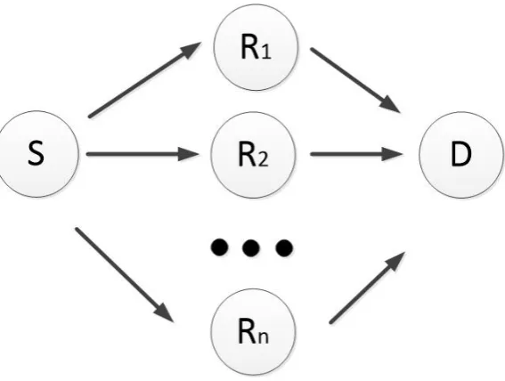
2.5 Multihop transmission. . . 29
2.6 Two-hop cooperative relay combining. . . 31
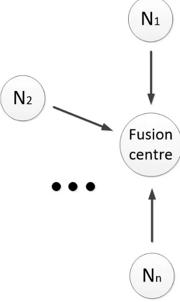
2.7 Decision fusion composed of fusion center and N nodes. . . 34
3.1 AF cooperative system with one source, one destination and
one relay. . . 48
3.2 Symbol frame for CCE and DCE. . . 50
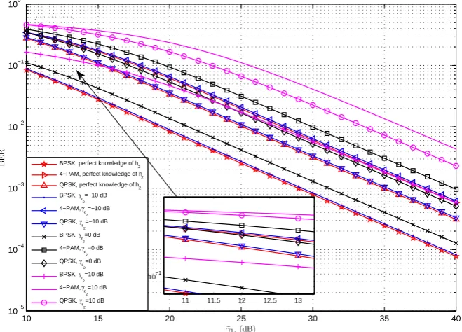
3.3 BER vs. γ¯1 for AF in DCE. (a) when h1 is estimated but
with the perfect knowledge of h2. (b) when bothh1 and h2 are
estimated with γε2 =−10 dB. . . 73
3.4 Comparison of BERs between the case whenh1is estimated but
with perfect knowledge ofh2 and the case when bothh1 and h2
3.5 BER vs. ¯γ1 for AF in CCE. (a) when Gdf ix1 and Gwf ix1 are
used. (b) when Gdf ix2 and Gwf ix2 are used. . . 76
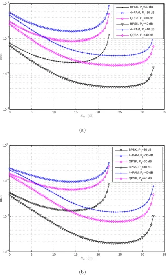
3.6 BERs vs. Ew1 for AF in DCE whenh1 is estimated but with the
perfect knowledge ofh2 with ¯γ2 = 30 dB. (a)d1 = 0.5,d2 = 0.5.
(b) d1 = 1, d2 = 1. . . 78
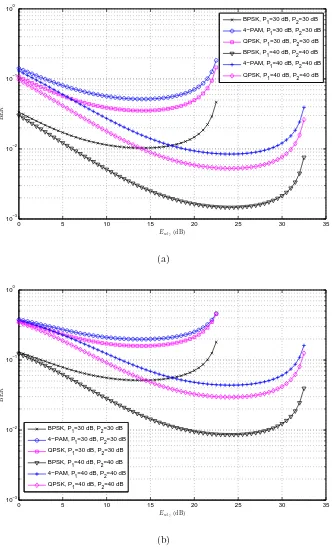
3.7 BER vs. Ew1 for AF in CCE when Gdf ix1 and Gwf ix1 are used.
(a) d1 = 0.5, d2 = 0.5. (b) d1 = 1, d2 = 1. . . 79
3.8 Comparison of BERs with optimal allocation between the case
when h1 is estimated but with perfect knowledge ofh2 and the
case when both h1 and h2 are estimated in DCE. . . 82
3.9 BER vs. PT/H for AF in DCE when both h1 and h2 are
esti-mated. (a) d1 = 1/4d2. (b) d1 = 1/10d2. . . 84
3.10 BER vs. PT/H for AF in CCE whenGdf ix2 andGwf ix2 are used.
(a) d1 = 1/4d2. (b) d1 = 1/10d2. . . 85
4.1 System model. . . 91
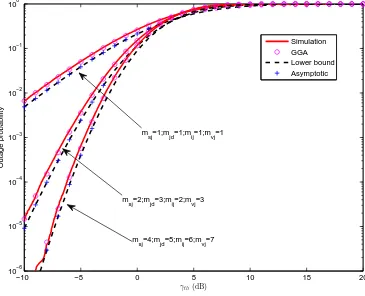
4.2 Outage probability vs. γth for random interferers when ¯γSIN R
= 15 dB, ¯γIN R = 0 dB, λ = 50, L = 10, β = 3, m
sj = 4 and
mjd = 5. . . 114
4.3 Outage probability vs. γth for random interferers when ¯γSIN R
= 15 dB, ¯γIN R = 0 dB, λ= 50, L= 10 and β = 3. . . 115
4.4 Outage probability vs. γth for random interferers when ¯γSIN R
= 15 dB, ¯γIN R = 20 dB, λ = 50, L= 10 and β = 3. . . 116
4.5 Outage probability vs. γth for random interferers when ¯γSIN R
4.6 Outage probability vs. γth for random interferers when ¯γSIN R
= 15 dB, ¯γIN R = 0 dB, λ= 50, L= 10 and β = 5. . . . 119
4.7 Outage probability vs. γth for random interferers when ¯γSIN R
= 15 dB, ¯γIN R = 0 dB, λ= 50, L= 20 and β = 3. . . . 120
4.8 Outage probability vs. γthfor fixed interferers when ¯γSIN R= 15
dB, ¯γIN R = 0 dB, msj = 4 and mjd = 5. . . 121
4.9 Outage probability vs. γthfor fixed interferers when ¯γSIN R= 15
dB and ¯γIN R = 0 dB. . . 122
4.10 Outage probability vs. γthfor fixed interferers when ¯γSIN R= 15
dB and ¯γIN R = 20 dB. . . . 123
4.11 Outage probability vs. γthfor fixed interferers when ¯γSIN R= 20
dB and ¯γIN R = 20 dB. . . . 124
4.12 Outage probability vs. γthfor fixed interferers when ¯γSIN R= 10
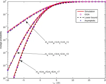
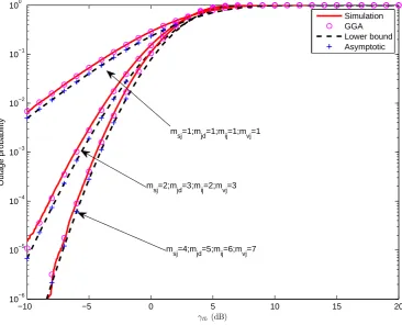
dB, msj = 2, mjd = 3, mij = 2 andmvj = 3. . . 125
5.1 Outage probability vs. γthusing EGC receivers in wireless
mul-tihop relaying system with interferences. . . 152
5.2 Outage probability vs. γthusing EGC receivers in wireless
mul-tihop relaying system without interferences. . . 153
5.3 Outage probability vs. γth in multiple scattering channel with
interferences. . . 154
5.4 Outage probability vs. γth in multiple scattering channel
with-out interferences. . . 155
5.5 Outage probability vs. γthin terms of SIR in multiple scattering
channel with interferences. . . 156
6.2 Choices of the best thresholds for the fusion rules using 2 bits, 3
bits and 4 bits at γ1=5 dB and L=3 in Rayleigh fading channels.171
6.3 BER curves comparing the simulation and the approximation
results using 1 bit to represent the observations made atL= 1,
2, 3, 4. . . 172
6.4 Comparison of BER curves for the decision rules using MRC,
using 1 bit, using 2 bits, using 3 bits and using 4 bits in Rayleigh
fading channels. . . 173
6.5 BER curves of MRC, (1, 2, 3), (1, 3, 4) and (2, 3, 4) fusion rules
at γ1 = 5 dB in Rayleigh fading channels. . . 174
6.6 BER curves of MRC, (1, 2, 3), (1, 3, 4), (2, 3, 4) fusion rules at
γ1 = 5 dB in Nakagami-m fading channels with m = 3. . . 175
6.7 BER curves of MRC, (1, 2, 3), (1, 3, 4) and (2, 3, 4) fusion rules
at γ2 = 10 dB in Rayleigh fading channels. . . 177
6.8 BER curves of MRC, (1, 2, 3), (1, 3, 4) and (2, 3, 4) fusion rules
List of Tables
2.1 Popular modulation schemes . . . 23
5.1 Comparison of exact and approximate PDFs of R= 2 X11
X21X31 + 3X12X22X32
X42X52 . . . 150 5.2 Comparison of exact and approximate CDFs of R = 2 X11
X21X31 + 3X12X22X32
X42X52 . . . 151
6.1 The values of best thresholds using 1 bit, 2 bits, 3 bits and 4
Abbreviations
AF Amplify-and-forward
ASK Amplitude-shift keying
AWGN Additive white Gaussian noise
BER Bit error rate
BPSK Binary phase-shift keying
BFSK Binary frequency-shift keying
CCE Cascaded channel estimation
CDF Cumulative distribution function
CDMA Code division multiple access
CSI Channel state information
DF Decode-and-forward
DCE Disintegrated channel estimation
EGC Equal gain combining
EHF Extremely high frequency
FSK Frequency-shift keying
GA Gamma approximation
GG Generalized Gamma
GGA Generalized Gamma approximation
GGRA Generalized Gamma ratio approximation
GRA Gamma ratio approximation
i.i.d. Independent and identically distributed
INR Interference-to-noise ratio
ISI Inter-symbol interference
LOS Line-of-sight
LMMSE Linear minimum mean squared error
LTE Long term evolution
MGF Moment generating function
MISO Multiple-input-single-output
MIMO Multiple-input-multiple-output
ML Maximal likelihood
M-PAM M-ary pulse amplitude modulation
MRC Maximal ratio combining
NCFSK Noncoherent frequency-shift-keying
PPP Poisson point process
PSK Phase-shift keying
QPSK Quadrature phase-shift keying
QoS Quality of service
RSP Ratio of sums of products
RV Random variable
SNR Signal-to-noise ratio
SRP Sum of ratios of products
SP Sum of products
SIR Signal-to-interference ratio
SIMO Single-input-multiple-output
SINR Signal-to-noise-plus-interference ratio
TDMA Time division multiple access
UHF Ultra high frequency
UWB Ultra-wideband
WLAN Wireless local area networks
WSNs Wireless sensor networks
Important Symbols
B(·,·) Beta function
E(·) Expectation operator
Gc,da,b(·) Meijer’s G-function
Kv(·)vth order modified Bessel function of the second kind
L−1(·) Inverse transformation operator
N(·,·) Normal distribution
V(·) Variance operator
Γ(·) Gamma function
Γ(·,·) Upper incomplete Gamma function
κν(·) Complete elliptic integral of the νth kind
2F1(·,·;·;·) Hypergeometric function.
ℜ(·) Real part
ℑ(·) Imaginary part
Q(·) Gaussian Q-function
sign(·) Signum function
Chapter 1
Introduction
1.1
Wireless Communications
With the extensive development of wireless technologies over the past four
decades, wireless communications have now become an indispensable part of
people’s daily lives and various industries. The attractive advantage of wireless
communication systems is that the mobile devices are free to take, move, install
and relocate with little additional cost of setting and rewiring. Also, it is very
convenient to add other wireless devices or remove some from the existing
systems without causing serious problems to the rest of systems, with proper
hardware and software configurations.
The information produced in a wireless source could be either a digital
signal, such as the signal in digital electronics, the output of a computer, or an
analogue signal, such as a temperature, light, sound or video signal. In digital
wireless communication systems, the information at source will be transformed
into a sequence of binary digits for transmission [1]. Compared with analog
have the advantage of high efficiency, flexibility, compatibility and reliability
[1]. Also, digital signals are more tolerant to noise and easy to store. The most
commonly used media of wireless communications can be radio waves but can
also be other electromagnetic technologies, such as infrared [2]. Radio waves
have the longest wavelength in the electromagnetic spectrum. The frequencies
of radio waves are between 3 Hz to 300 GHz. Microwaves can be considered
as a sub-class of the radio waves that start from UHF (ultra high frequency)
to EHF (extremely high frequency) which cover the frequencies between 300
MHz to 300 GHz. The higher frequencies of microwaves are called millimeter
waves which may be applied in future 5G cellular communications to tackle
the bandwidth shortage problems [3, 4].
Over the past several years, many types of wireless communication
sys-tems have been proposed, such as wireless personal area networks (WPAN),
wireless local area networks (WLAN), wireless metropolitan area networks
(WMAN) and wireless wide area networks (WWAN). The wireless
technolo-gies have also been developed rapidly, including bluetooth, ad hoc networks,
ZigBee, Ultra-wideband (UWB), wireless fidelity (Wi-Fi), worldwide
interop-erability for microwave access (WiMax), etc.
1.2
Evolution of Mobile Communication
Sys-tems
The last four decades have seen unprecedented growth in mobile
communica-tion systems. The evolucommunica-tion and features of wireless mobile communicacommunica-tion
In the early 1980s, the first-generation or 1G network was launched
based on frequency division multiple access (FDMA), which can only provide
the basic mobile speech service using the analogue cellular technologies.
Around the late 1980s, second-generation or 2G network was
intro-duced, based on code division multiple access (CDMA) or time division
mul-tiple access (TDMA) technologies, which provided better coverage and
spec-trum efficiency than 1G. In 1991, Global System for Mobile Communications
(GSM) was launched, which can allow people to use picture messages (MMS),
text messages (SMS), emails and Internet services (WAP). Then, the General
Packet Radio Service (GPRS) was introduced (or referred as 2.5G), which
added packet switched capability to existing 2G networks, improving services
such as e-mail and Internet access. Later in 2003, enhanced data rates for
GSM evolution (EDGE) was developed (referred as 2.75G or enhanced GPRS),
which is considered as a pre-3G communication technology. It can provide
typ-ical bit rates of up to 400 kbit/s and peak bit rates of up to 1 Mbit/s.
Third-generation or 3G network was introduced in late 2002, which
brought us faster Internet services and video calling. In 3G network, some
uni-versal global standards were designed and defined by International
Telecommu-nication Union (ITU) and its partners such as the 3rd Generation Partnership
Project (3GPP). Universal Mobile Telecommunications System (UMTS) was
used in Europe and it selected wideband code division multiple access
(W-CDMA) as an air interface. Time division synchronous code division multiple
access (TD-SCDMA) was proposed in China, and code division multiple
ac-cess 2000 (CDMA2000) EV-DO was used in the United States. Shortly after
3G, high speed packet access (HSPA) protocols (or referred to as 3.5G) were
uplink and 14 Mbit/s in the downlink. Later in 2008, a further improved
stan-dard, HSPA+ (or referred to as Evolved HSPA), was released, which brought
the data rates of the uplink and downlink to around 22 Mbit/s and 168 Mbit/s,
respectively.
Two fourth-generation or 4G standard candidates: worldwide
interop-erability for microwave access (WiMAX) and long term evolution (LTE) were
first commercially deployed at around 2007 and 2009, respectively. WiMAX
was introduced by WiMAX Forum, which was described as “a standards-based
technology enabling the delivery of last mile wireless broadband access as an
alternative to cable and DSL” [5]. LTE was developed by 3GPP, which is a
natural upgrade path for UMTS, HSPA and EDGE networks. Their purposes
were both for high speed data transmission and high capacity of mobile phones
and data terminals. The above two wireless technologies cannot be called as
true 4G as they did not meet the technical requirements set by ITU.
In 2010, WirelessMAN-Advanced (known as IEEE 802.16m or Mobile
WiMAX) standardized by IEEE and LTE-Advanced standardized by 3GPP
reached the ITU requirements and became the true 4G standard. Several core
techniques have been investigated and adopted in LTE-Advanced, such as
multiple-input-multiple-output (MIMO), orthogonal frequency-division
mul-tiple access (OFDMA), cooperative wireless communications, heterogeneous
deployment networks, self-organizing operation [6]. In particular, relaying via
cooperative wireless communications has been considered as one of the key
technologies in the future generation commercial wireless communication
1.3
Cooperative Wireless Communications
Recently, the demands for lower bit error rate (BER), larger system capacity,
better quality of service (QoS) and wider coverage area have been increasing
rapidly. However, the performance of wireless communication systems is
al-ways influenced by path loss, interference from other users, fading in wireless
channels, etc. In high density mobile environments, such as in big cities, the
mobile terminals are often subject to multi-path deep fading. To reduce the
degradation of signal integrity, diversity is important in receiving the correct
information. The core idea of diversity is that different antennas can receive
different copies of the the signal. The chances of all these versions being in
a deep fade is much smaller than one signal being in a deep fade, if they are
independent. A simple two-branch transmit diversity technique for wireless
communications was proposed in [8].
Traditional space diversity systems using multiple antenna arrays
de-ployed at the transmitter and/or the receiver are proposed to address these
challenges. Based on the number of antennas, they can be mainly categorised
as single-input-multiple-output (SIMO), multiple-input-single-output (MISO)
and MIMO. Multiple antenna arrays can potentially and theoretically
com-bat multipath fading propagation effects and increase the channel capacity by
sending and receiving multiple copies. However, they may be physically
com-plex, large-size and not cost-efficient. Therefore, in mobile communication
systems, it is more practical to install multiple antennas in the base station
than in the mobile node as the node is always complexity-limited and
power-limited.
which are composed of multiple mobile nodes, have come into being [9, 10].
They enable single-antenna mobiles to have part of the advantages of the
MIMO systems. In this case, multiple users / sensors / nodes can cooperate
with each other and share their antennas as relays. In this sense, they can
create a virtual MIMO system, thereby generating virtual multiple antenna
arrays and improving the performance of their own and the whole networks.
These nodes not only have their own information to send, but also can act as
relays to help other mobile nodes to transmit. Thus, they can combat and
mitigate the deleterious effects of fading by sending and receiving multiple
independent copies of the same signal, and they can effectively improve the
QoS and enhance the transmission robustness of the networks.
Also, cooperative wireless systems can extend the network coverage by
using idle nodes as relays or multihops in the network [11]. Since the power
consumed by sending the signal through direct link by a signal antenna can
be very high if the transmission distance is long, it is not acceptable by some
mobile node which is power-limited or battery-driven. Cooperative relaying
can overcome the problem of the insufficient power in transmitting the signal
in long distance, as it can shorten the transmission distance between each
mobile node by using relays or multihops. The joint routing, scheduling and
power control problem for multi-hop wireless networks were studied in [12].
Another advantage of cooperative wireless systems is by using
interme-diate relay nodes, the systems can deal with the path loss concerns to some
extent. Because the whole transmission distance between the source and
des-tination can be divided into at least two parts by the intermediate relay nodes.
It is shown in [13] that the sum of path loss of each part is less than the path
gain [13].
Several aspects of the design and optimization of conventional coded
multiple-antenna transmission diversity methods are explored in [14].
Com-pared with traditional space diversity systems [14], cooperative wireless
com-munication systems can achieve the same diversity gain as the traditional space
diversity system without the installation of multiple antennas at the source or
at the destination. It was also reported in [10] that less power is required
in cooperative wireless systems than the conventional methods to achieve the
same level of performance.
Distributed space-time coded cooperative diversity protocols for
com-bating multipath fading in wireless networks were proposed in [15]. Several
practical implications, signal schemes, and requirements on system design for
cooperative communication systems were discussed in [7]. They provide an
effective way for multiple wireless nodes to cooperate with each other, thereby
exploiting spatial diversity in the network. Also, the low-complexity
cooper-ative diversity protocols are developed and analyzed in [10]. They considered
certain implementation constraints in the cooperating networks, such as
half-duplex transmission, nonergodic and delay-constrained scenarios.
The new cooperative transmission protocols for delay-limited coherent
fading channels composed of half-duplex nodes were proposed in [16].
Sin-gle, multiple relay selection and their achievable diversity orders were studied
in [17]. Relay selection by allowing more than one relay to cooperate was
generalized and several SNR-suboptimal multiple relay selection schemes were
proposed in [17]. The power allocation problem in the transmit diversity
wire-less systems in Rayleigh fading with mean channel gain information was
the total power constraint was considered in [18]. The optimal joint relay
se-lection and power allocation scheme for two-way relay networks were proposed
in [19]. The scheme in [19] was based on the maximization of the smaller of
the received SNRs of the two transceivers subject to the total transmit power
constraint. Apart from power allocation, [20] has proposed to design
coopera-tive communication protocols by considering time domain as well. Then, [20]
has shown that one should allocate more time and energy to the source than
the relay.
In [21], the relay-based multi-user cooperative communication systems
for the 4G uplink have been proposed. In the system, the multiple users’
data streams are coded at the relay and then being forwarded to the base
station. Also, the low-complexity coded modulation schemes in 4G wireless
systems for distributed relaying have been studied in [22]. The block-based
selective orthogonal frequency division multiplexing decode-and-forward
relay-ing schemes for 4G systems have been proposed in [23], while the relay based
cellular broadband networks of low complexity and low cost for suburban
en-vironment have been studied in [24]. In [25], relay nodes with the interference
consisting of two single antenna transmitters and receivers have been studied.
The relay systems have also been studied for the 5G systems [26]. In [26],
two-way wireless relaying with multiple antennas using decode and forward
protocol for 5G systems have been presented.
To sum up, cooperative wireless communications are expected to
pro-vide significant improvement in terms of system capacity, network coverage,
reception reliability, energy efficiency, device size, cost and hardware
imple-mentation [10]. Because of these advantages, cooperative wireless relaying
They have recently been adopted by several new wireless standards, such as
Mobile Multihop Relay (MMR, IEEE 802.16j), WiMAX (IEEE 802.16m) [27]
and LTE-Advanced standard (3GPP) [28].
1.4
Thesis Outline
1.4.1
Research Motivation
Although cooperative wireless relaying communication systems has been
ex-tensively researched and applied as an effective way to mitigate the detrimental
effects of wireless channels, there are still a lot of problems which need to be
considered thoroughly.
First of all, for early research in cooperative relaying networks, perfect
channel state information (CSI) is assumed to be available at some or all the
network nodes. However, in reality, the training process is always necessary
for a node to obtain an estimate of the exact CSI. Such estimation is always
imperfect owing to the existence of fading or noise. Thus, the channel
esti-mation process is important in wireless relay communications [29]. Recently,
two channel estimation methods, i.e. disintegrated channel estimation (DCE)
and cascaded channel estimation (CCE) are used in most wireless relaying
systems [30]. However, DCE and CCE considering performance, power
effi-ciency and complexity are still not available and are urgently needed. Also, in
practice, the total power assigned to each node or to the whole networks are
often limited such that an optimal power allocation method between the pilots
(use for channel estimation in the training process) and the data (use for
power allocation method between the source node, relay and destination node
is also required.
Secondly, in cooperative wireless system, existing work has mainly
fo-cused on the ideal situation with no interference during the relaying
trans-mission process. Although this assumption can simplify theoretical analysis
and present useful insights, it cannot be applied in practical scenarios, such
as in simultaneous multi-user transmissions [31]. In reality, the nodes usually
suffer from interference and the interference always causes the degradation of
the performance of the system, which can not be ignored in the practical
sys-tem analysis and design. For the applications in multiple-access syssys-tems with
mobile nodes, the number and the locations of the interferers can be random
while for the applications in fixed-access wireless systems with fixed nodes,
the number and the locations of the interferers can be fixed. Therefore, the
performance analysis for cooperative wireless systems with either random or
fixed interferers is needed, as they can provide a number of useful insights and
suggestions to the design of practical cooperative systems.
Then, for multihop relaying and multiple scattering channels, the
sys-tem structure is more complex than the dual-hop wireless channels. Therefore,
the exact results in terms of BER and outage probability are very complicated
to obtain and not convenient to use, most of which have no closed-form
ex-pressions or are in terms of complicated special functions. If considering
inter-ference in those systems, their structure becomes even more complex than the
systems without considering interference. Therefore, proper approximation
methods with simplified form for those systems are highly required.
Last, but not least, decision making is essential in wireless
and cognitive radio [32]. Since there are a variety of impairments such as noise,
attenuation, fading, interference and distortion contributing to errors in the
wireless channels, which will affect the signal transmission, it is important to
understand how to receive the information transmitted by the source to the
maximum possible extent. Therefore, the best fusion rule is highly needed in
wireless communication systems.
1.4.2
Chapter Outlines
Motivated by the above observations, the performance of the cooperative
wire-less communications is analytically evaluated in this thesis, while taking several
realistic conditions into account. Approximate methods with simplified form
and the best fusion rule are provided for specific applications. An
introduc-tion and conclusion are given in most chapters to provide the readers with
overviews and summaries of these chapters. Mathematical derivations and
ex-pressions are provided and several practical scenarios of cooperative wireless
systems are examined and discussed. Numerical results are also given to
ver-ify those derivations and insights are presented as well. The structure of this
thesis is organized as follows.
In Chapter 2, several fading channels used in this thesis are introduced
while a review of modulation schemes including higher order modulations is
given. Then, a comprehensive overview of the cooperative wireless relaying
is presented. The details of the two main decision methods, i.e. soft-decision
and hard-decision, are also discussed in this chapter. Finally, widely used
performance measures for evaluating the system and related research methods
In Chapter 3, BER and outage probability expressions for
amplify-and-forward (AF) relaying systems with two different channel estimation methods,
DCE and CCE, using a pilot-aided maximum likelihood method in slowly
fading Rayleigh channels, are derived. Based on the BERs, the optimal values
of pilot energy under the total transmitting energy constraints at the source
and the optimal values of pilot energy under the total transmitting energy
constraints at the relay are obtained, separately. Moreover, the optimal energy
allocation between the pilot energy at the source, the pilot energy at the relay,
the data energy at the source and the data energy at the relay are obtained
when their total transmitting energy is fixed.
In Chapter 4, the outage probability performance of a dual-hop AF
selective relaying system with global relay selection is analyzed for
Nakagami-m fading channels in the presence of multiple interferers at both the relays
and the destination. Two different cases are considered in this chapter. In
the first case, the number of interferers is assumed to be random, as are
their locations. Outage probability using the generalized Gamma
approxi-mation (GGA) in the form of a one-dimensional integral is derived. In the
second case, the number and locations of the interferers are assumed to be
fixed. Exact outage probability in the form of a one-dimensional integral is
derived. For both cases, closed-form expressions of lower bounds and
asymp-totic expressions for high signal-to-interference-plus-noise ratio (SINR) are also
provided. Simplified closed-form expressions of outage probability for special
cases (e.g., dominant interferences, independent and identically distributed
interferers, Rayleigh distributed signals) are studied.
In Chapter 5, exact results for the probability density function (PDF)
(SRP) and the sum of products (SP) of independent α - µ random variables
(RVs) are derived. They are in the form of a one-dimensional integral based on
the existing works on the products and ratios ofα-µRVs. To simplify the
ex-act results, approximate expressions in closed-form are also provided as follows:
generalized Gamma ratio approximation (GGRA) is proposed to approximate
SRP; Gamma ratio approximation (GRA) is proposed to approximate SRP
and the ratio of sums of products (RSP); GGA and Gamma approximation
(GA) are used to approximate SP. The proposed results of the SRP can be
used to calculate the outage probability for wireless multihop relaying systems
or multiple scattering channels with interferences. The proposed results of the
SP can be used to calculate the outage probability for these systems without
interferences. Also, the proposed approximate result of the RSP can be used
to calculate the outage probability of the signal-to-interference ratio (SIR) in
a multiple scattering system with interference.
In Chapter 6, a new hard decision fusion rule that combines arbitrary
numbers of bits for different samples taken at different nodes is proposed. The
best thresholds for the fusion rules using 2 bits, 3 bits and 4 bits are obtained
through simulation. The BER for the hard fusion rule with 1 bit is also derived
using characteristic function. The new scheme shows that there is a tradeoff
between performance and energy penalty in the decision fusion rule in wireless
communication systems.
Finally in Chapter 7, the research results and findings are summarized
and discussed. Also, the possible future work directions and suggestions are
Chapter 2
Background
2.1
Channel Models
Mathematical models are usually applied in wireless communication systems
to characterize the physical channels and to clearly and conveniently reflect
the important characteristics of the transmission medium. In the following, a
brief introduction of the mathematical models that are used in this thesis is
provided.
2.1.1
AWGN
The simplest model to describe the practical communication model is the
additive noise channel. In this case, the transmitted signals(t) is influenced by
an additive random noise, which may be caused by amplifiers or interference.
If this noise is generated mainly by amplifiers at the receiver or electronic
components, it can be named as thermal noise. This sort of noise can be
generalized statistically to a Gaussian noise process [1]. Therefore the model
Due to its mathematical tractability and application to a large class of physical
channels, it has been applied to many system analyses and research [1]. The
mathematical model of AWGN is
u(t) = s(t) +n(t) (2.1)
where u(t) is the received signal in the communication system, n(t) is the
additive white Gaussian noise in the channel andtis the discrete time symbol.
The PDF of a Gaussian RVX is described in terms of the meanµand variance
σ2 as
fX(x) = 1
√
2πσ2e
−(x−µ)2
2σ2 . (2.2)
Denote that X follows the Gaussian distribution (or Normal distribution) as
X ∼N(µ, σ2). The CDF of a Gaussian RV is defined as
FX(x) = 1−Q(
x−µ
σ ) (2.3)
whereQ(·) is the Q function defined as [1]
Q(x) = √1
2π ∫ ∞
x
e−t
2
2 dt. (2.4)
Also, Q function can be approximated as [1]
Q(x)≈ 1
2e −x2
2 , x >0. (2.5)
Note that (2.5) is a very good approximation for Gaussian Q-function normally
2.1.2
Rayleigh Fading Channels
Apart from being influenced by the thermal noise, the transmitting signal
usually undergoes fading through wireless channels as well. When a signal
experiences fading during transmission, both its phase and envelope fluctuate
over time.
Depending on the nature of the radio propagation, there are different
models describing the statistical behaviour of the fading channel. The basic
one of them is Rayleigh fading channel [34], which can be applied to describe
the multipath fading with no direct line-of-sight (LOS) path. Rayleigh fading
can be used in tropospheric and ionospheric signal propagation as well as
heavily built-up urban environment [1]. Rayleigh fading is a reasonable model
for the environment where there are many objects scatter the radio signal
before it reaches the destination. Following the central limit theorem, if there is
sufficiently scatter and no direct LOS path, then the channel impulse response
will be well-modelled as a Gaussian process and have zero mean and phase
evenly distributed between 0 and 2 π radians [35]. If X1, X2 are assumed to
be two independent and identically distributed (i.i.d.) Gaussian RVs such that
X1, X2 ∼N(0, σ2), then
X =
√
X2
1 +X22 (2.6)
is a Rayleigh RV. Thus, the PDF of a Rayleigh RV is given by
fX(x) = x
σ2e
−x2
2σ2, x≥0. (2.7)
Rayleigh RV is given by
FX(x) = 1−e− x2
2σ2, x≥0. (2.8)
If the instantaneous SNR per symbol is defined as γ = X2Es/N0 and the
average SNR per symbol as ¯γ = ΩEs/N0, where Es is the energy per symbol,
Ω =E(X2),E(·) is the expectation operator,X2 is the received instantaneous
signal power such that E(X2) = 2σ2 and N
0 is the power of the Gaussian
noise, the instantaneous SNR follows an exponential distribution with the
PDF as [34]
fγ(γ) = 1 ¯
γe
−γ
¯
γ, γ >0. (2.9)
2.1.3
Ricean Fading Channels
If X1 and X2 are distributed as X1 ∼ N(µ1, σ2) and X2 ∼ N(µ2, σ2)
respec-tively, then,X =√X2
1 +X22 can be defined as a Ricean RV which is used to
describe the multipath fading when one of the paths, typically a line of sight
signal, is much stronger than the others. Thus, the PDF of a Ricean RV is
given by [1, pp. 50]
fX(x) = x
σ2I0(
sx
σ2)e
−x2+s2
2σ2 , x >0 (2.10)
wheres =õ2
1+µ22 and I0(x) is written as I0(x) =
∑∞
0 (
xk
2kk!)2.
2.1.4
Nakagami-
m
Fading Channels
The Nakagami-m distribution gives the general version of the Rayleigh
parameterm. The PDF of a Nakagami-m RV X can be given by [1]
fX(x) =
2mmx2m−1
ΩmΓ(m) e −mx2
Ω , x≥0 (2.11)
where Ω is defined as Ω =E(X2) andm is defined as the ratio of moments or
the fading parameter ranging from 1/2 to∞ as [1]
m = Ω
2
E[(X2−Ω2)2]. (2.12)
In (2.12), m=1 gives the Rayleigh model and Γ(·) is the Gamma function
which is defined as Γ(z) = ∫0∞tz−1e−tdt [36].
Simulators for the Rayleigh and Nakagami fading channels were
re-ported in [37, 38]. Then, following the definition as in (2.9), the instantaneous
SNR γ of (2.11) is distributed according to a gamma distribution with the
PDF given by [34]
fγ(γ) =
mmγm−1
¯
γmΓ(m)e
−mγ
¯
γ , γ ≥0. (2.13)
The Nakagami-mfading channel can provide more flexible and accurate match
to the experimental signal statistics than the Rayleigh fading channel. Also,
Nakagami-m fading can be used to model fading channel either more or less
severe than Rayleigh fading by adjusting the parameterm [1]. [39] has shown
that the Nakagami-m fading can provide the best fit for the data signals
re-ceived in urban radio multipath channels.
2.1.5
α
-
µ
Fading Channels
The α - µ distribution, which is in fact a rewritten form of the generalized
fading, as it includes the distributions of Gamma, Nakagami-m, exponential,
Weibull, one-sided Gaussian, central Chi-squared and Rayleigh fading [40].
The PDF of aα - µRV X is [40]
fX(x) =
αµµ
Γ(µ)ˆγαµx
αµ−1e−µxαγαˆ , x≥0
(2.14)
where α > 0 is related to the non-linearity of the environment [41], ˆγ =
E1/α(Xα) is a α-root mean value, µ = E2(Xα)
V(Xα) is the inverse of the
normal-ized variance of Xα, and V(·) are the variance operators [40]. One can get
Nakagami-m fading when setting α = 1, Weibull fading when setting µ = 1
and Rayleigh fading when settingα =µ= 1 in (2.14). α-µfading can be used
to explore the non-linearity of the propagation medium, as sometimes fading
model like Nakagami-m fading may not result in a moderate fitting [42]. [43]
has shown that α - µ distribution can describe a signal composed of clusters
of multipath waves propagating in a nonhomogeneous environment.
2.1.6
Characteristics of Fading Channels
Slow and Fast Fading
If the coherence time of the channel Tc is larger than the symbol duration
time Ts, the channel can be defined as the slow fading channel, while if the
coherence timeTc is smaller than the symbol duration time Ts, the channel is
called as the fast fading channel [34]. The coherence timeTc can be related to
the channel Doppler spread fd as
Tc≃
1
fd
Frequency Flat and Frequency Selective Fading
If the transmitted signal bandwidth fs is much smaller than the coherence
bandwidth of the channel fc, the channel is called as frequency flat fading,
while if the signal bandwidthfs is much larger than the coherence bandwidth
of the channel fc, the channel is called as frequency selective fading. The
coherence bandwidth of the channelfcis related to the maximum delay spread
τmax given by [34]
fc ≃
1
τmax
. (2.16)
2.2
Modulation Scheme
The data which needs to be transmitted through wireless channels can be both
an analog signal or a digital signal. Digital signal transmission is more popular
than the analog signal transmission. For instance, digital audio broadcasting
(DAB) and digital video broadcasting (DVB) systems can broadcast radio
and video signals through terrestrial digital transmissions, which allow for
more efficient uses of frequency spectrum and can provide better quality of
the sound and picture than traditional analogue methods.
Before transmission, the transmitted signal has to be encoded using
ei-ther analog or digital modulation techniques to fit the channel. There are
basi-cally three types of analog modulation schemes: frequency modulation (FM),
amplitude modulation (AM) and phase modulation (PM); while there are also
three major classes of digital modulation techniques: frequency-shift keying
(FSK), amplitude-shift keying (ASK) and phase-shift keying (PSK) [34]. The
major advantage that digital modulation has over analog is that it can achieve
1 and any noise is virtually eliminated once the receiver decides whether a 0
or a 1 was transmitted. In the following, some modulation schemes used in
this thesis will be introduced.
2.2.1
Binary Phase Shift Keying
Introduction
PSK is the digital modulation scheme that can convey the transmitted data
through the phase of the carrier wave by modulating the reference signal. In
this case, the digital data can be represented by a finite number of distinct
signals. For instance, theM signal waveforms can be represented by [1]
s(t) = Re{g(t)ej2π(mM−1)e
j2πfct
}, m= 1,2,· · · , M (2.17)
where g(t) is the signal pulse shape and 2π(mM−1), m = 1,2,· · · , M is the M
possible phases of the carrier andfcis the carrier frequency. A convenient way
to represent PSK schemes is to use a constellation diagram, such as
constella-tion diagram for binary phase shift keying (BPSK) and quadrature phase-shift
keying (QPSK) as follows [1]
BPSK is the modulation with the robust and simplest implementation,
which attracts great interest among the researchers and applications. It has
only two phase states which are represented by the sinusoid, and two phases are
different by 180 degree. During the modelling and calculation, s(t) is always
denoted as 1 and -1 for its two states. If one considers the signal transmitting
in AWGN, the received signal y(t) can be denoted as follows:
y(t) =√Ed+n(t) (2.18)
where Ed is the transmitted signal energy per symbol when 1 is transmitted
and,
y(t) =−√Ed+n(t) (2.19)
when -1 is transmitted [1]. In the performance analysis below, the time indexes
will be omitted.
Performance Analysis
In BPSK modulation, assume the probabilities of sending message 1 and -1
are p and 1−p, respectively, and assume s1 =
√
Ed and s2 =−
√
Ed . Using
(2.18) and (2.19), and defining the decision threshold asrth, then the decision
regions can be shown as Fig. 2.2. Thus, the BER performance can be given
Table 2.1: Popular modulation schemes
Attributes Characteristics
Carrier schemes Frequency, phase, amplitude. Number of bits If the alphabet consists of M = 2N
alternative symbols, each symbol represents a message of N bits.
Detection methods Coherent, noncoherent, differentially coherent, partially coherent.
as [1]
Pe=p
∫
D2
P r(y|s=√Ed)dy+ (1−p)
∫
D1
P r(y|s=−√Ed)dy
=p Q(
√
E√d−rth
N0 2
) + (1−p)Q(rth+
√
Ed
√ N0
2
)
(2.20)
If p = 1/2, one can have rth = 0, and the error probability can be simplified
as
Pe=Q
(√ 2Ed
N0
)
(2.21)
where Q(·) is the Gaussian Q-function and N0 is the noise power. BPSK
signaling can be used with rectangular pulses, which has constant envelope.
However, in practice, filtered pulse shapes are more preferred and employed [1].
Also, a root-raised-cosine filter (RRC) are usually used as the transmit and
receive filter in the digital communication system to perform matched filtering,
2.2.2
Higher Order Modulations
Higher-order modulation schemes are the modulations usually with an order
of four or higher such as QPSK, and 4-pulse amplitude modulation (4-PAM).
Although BPSK gives the better BER performance than QPSK and 4-PAM,
QPSK and 4-PAM can transmit twice the data rate in a given bandwidth
compared to BPSK. Thus there is a tradeoff between reliability and data rate.
Other popular modulation schemes can be a combination of the
at-tributes listed in Table. 2.1, which are based on (1) carrier schemes, such as the
frequency, phase and amplitude; (2) the number of levels assigned to the
mod-ulated carrier schemes; (3) the detection schemes, such as coherent, partially
coherent, noncoherent, differentially coherent [34]. According to the needs
of specific wireless communication channels, sometimes a more sophisticated
modulation scheme is required, which can be realized by modulating more
than one attribute, such as modulating phase and amplitude together. This
can satisfy the performance / power / bandwidth / reliability requirements
of the specific system channel. Details and analysis about these modulation
schemes are presented in Chapter 3 of [34].
2.3
Cooperative Wireless Relaying
Nowadays, cooperative wireless relaying has been extensively studied as an
effective way to provide extra spatial diversity, combat fading, enhance the
reliability and improve QoS in conventional single antenna transceiver
sys-tems [9, 44–47]. Most recently, cooperative wireless relaying has been adopted
in LTE-Advanced as a key technique for future generation wireless
A typical cooperative wireless communication system with a
coopera-tive diversity link is shown in Fig. 2.3 [44]. In Fig. 2.3, the source terminalS
Figure 2.3: A typical cooperative wireless communication system with a co-operative diversity link.
can not only communicate with the destination terminal D directly but also
can communicate through a relay R to D. In this case, the communication
period can be divided into two intervals. In the first interval,S communicates
with theR andDwhile in the second interval, only the relayR communicates
with D. The destination D can combine the two received signals from those
two transmission periods. In this system, one can see that if the direct link
is faded deeply, then the relay link is an effective way to compensate for that,
which may still achieve the acquired performance. The end-to-end
perfor-mance analysis and a selection combining scheme for this system is presented
in [44].
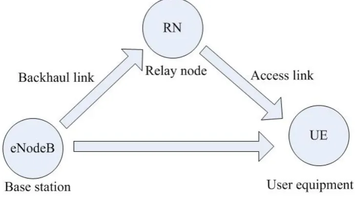
In the LTE-Advanced standard, source terminalS in Fig. 2.3 is referred
as user equipment (UE) andR in Fig. 2.3 is referred to as a relay node (RN),
as in Fig. 2.4. The link between eNodeB and RN is denoted as a backhaul
link or Un interface, whereas the link between RN and UE is denoted as access
[image:51.595.138.502.209.411.2]link or Uu interface. The eNodeB can transmit the signal at a higher power,
Figure 2.4: Cooperative wireless relaying in LTE-Advanced standard.
which is able to cover a larger area than the RN. Thus, each UE can either
communicate with the eNodeB via the help of low-power RNs or directly with
the eNodeB. In this case, the remote UEs or cell edge UEs can be well served
and therefore the capacity and coverage of the network can be improved [6].
2.3.1
Cooperative Techniques and Performance
Analy-sis
Several cooperative strategies have been proposed in the past few years, such as
AF, decode-and-forward (DF) [10], compress-and-forward (CF) [48], and coded
cooperation [49]. Among them, AF (non-regenerative) and DF (regenerative)
broadcasts its information to the relays in the first phase and then the relays
simply amplify the received signals from the source and forward them to the
destination in the second phase, while in DF relaying, the source broadcasts its
information in the first phase but the relays have to decode the received signals
from the source and then re-encode the signals before forwarding them to the
destination [9]. AF relaying can be seen as an analog cooperative method
whereas DF relaying can be seen as a digital cooperative method. For systems
with relatively bad backhaul links, AF relaying is more favourable than DF
relaying [6].
For AF relaying in the LTE-Advanced standard, the relay node RN only
operates as a repeater, such that the signals are simply amplified and forwarded
from the eNodeB to the UE. Thus, only the radio frequency protocol layer is
equipped in RN [50]. Also, the interference or the noise are amplified by the RN
to the UE in this case. For DF relaying in the LTE-Advanced standard, the RN
first decodes the transmitted signal from the eNodeB and then re-encodes the
signal to the UE. In this case, the radio frequency layer and physical layer are
both needed in RN [50]. Therefore, DF relaying has a more complex structure
than AF relaying and the processing delay in DF relaying in terms of decoding
and encoding can be longer than AF relaying [50]. However, DF relaying has
better received SINR than AF relaying as the noise and the interference can be
removed in DF relaying. Due to the lower complexity and simpler structure,
AF relaying is more attractive than DF relaying for some source-limited or
power-limited applications [46]. End-to-end performance of two-hop wireless
communication systems with AF relaying over flat Rayleigh fading channels
is analyzed in [47]. Outage probability and average BER expressions for noise
AF relaying can be further categorized into relays with channel state
information (CSI) and relays without CSI (blind relaying). For the former
case, the relays can use instantaneous CSI of the first hop to control the
amplification gain. Thus, in this case, the power of the retransmitted signal in
the relay side can be fixed [46]. For the latter case, relays without CSI do not
need instantaneous CSI of the first hop but use the fixed amplification gain.
In this case, the power of the retransmitted signal in the relay side is variable
[46]. Although the relays with CSI have better performance than the relays
without CSI, an estimator is needed to obtain CSI in CSI-aided relays and
therefore, the complexity of relays with CSI increases [46]. The exact outage
probability of two-hop CSI-aided AF relaying over Nakagami-mfading channel
is proposed in [51]. A comprehensive framework for the performance analysis
of AF relaying with CSI-assisted over several fading channels is presented
in [52]. In [52], a simple lower bound for outage probability is given based on
the moment generating function (MGF).
In a multiple-access system or a frequency-reused cell, interference from
other transmitting sources, i.e. interferers, may cause a performance
degrada-tion and therefore, cannot be ignored in the performance analysis. In [53], the
outage probability and average BER of a dual-hop relaying system with fixed
gain over Nakagami-m fading channel in the presence of a single interferer are
investigated. It was shown in [53] that the presence of the interferer at the
destination and at the relay leads to a floor point in the BER performance
and outage probability. A tight lower bound for BER of dual-hop AF with
CSI-aided over Nakagami-m fading channel in the presence of multiple
inter-ferers at the relay is derived in [54]. Closed-form expressions for the exact