warwick.ac.uk/lib-publications
Original citation:
Xu, Yakai, Gao, Weiguo, Yu, Yuhan, Zhang, Dawei, Zhao, Xiangsong, Tian, Yanling and Cun,
Huaying. (2017) Dynamic optimization of constrained layer damping structure for the
headstock of machine tools with modal strain energy method. Shock and Vibration, 2017.
2736545.
Permanent WRAP URL:
http://wrap.warwick.ac.uk/94034
Copyright and reuse:
The Warwick Research Archive Portal (WRAP) makes this work of researchers of the
University of Warwick available open access under the following conditions.
This article is made available under the Creative Commons Attribution 4.0 International
license (CC BY 4.0) and may be reused according to the conditions of the license. For more
details see:
http://creativecommons.org/licenses/by/4.0/
A note on versions:
The version presented in WRAP is the published version, or, version of record, and may be
cited as it appears here.
Research Article
Dynamic Optimization of Constrained Layer Damping
Structure for the Headstock of Machine Tools with Modal
Strain Energy Method
Yakai Xu,
1Weiguo Gao,
1Yuhan Yu,
2Dawei Zhang,
1Xiangsong Zhao,
1Yanling Tian,
1,3and Huaying Cun
41Key Laboratory of Mechanism Theory and Equipment Design, Ministry of Education, Tianjin University, Tianjin 300072, China 2School of Electrical Engineering and Automation, East China Jiaotong University, Nanchang 330013, China
3School of Engineering, University of Warwick, Coventry CV4 7AL, UK
4Shenji Group Kunming Machine Tool Company Limited, Kunming 650203, China
Correspondence should be addressed to Weiguo Gao; [email protected]
Received 3 November 2016; Accepted 31 January 2017; Published 22 February 2017
Academic Editor: Sergio De Rosa
Copyright © 2017 Yakai Xu et al. This is an open access article distributed under the Creative Commons Attribution License, which permits unrestricted use, distribution, and reproduction in any medium, provided the original work is properly cited.
Dynamic stiffness and damping of the headstock, which is a critical component of precision horizontal machining center, are two main factors that influence machining accuracy and surface finish quality. Constrained Layer Damping (CLD) structure is proved to be effective in raising damping capacity for the thin plate and shell structures. In this paper, one kind of high damping material is utilized on the headstock to improve damping capacity. The dynamic characteristic of the hybrid headstock is investigated analytically and experimentally. The results demonstrate that the resonant response amplitudes of the headstock with damping material can decrease significantly compared to original cast structure. To obtain the optimal configuration of damping material, a topology optimization method based on the Evolutionary Structural Optimization (ESO) is implemented. Modal Strain Energy (MSE) method is employed to analyze the damping and to derive the sensitivity of the modal loss factor. The optimization results indicate that the added weight of damping material decreases by 50%; meanwhile the first two orders of modal loss factor decrease by less than 23.5% compared to the original structure.
1. Introduction
As one of important kinds of CNC machine tools, high speed precision horizontal machining center is the key equip-ment in automotive, aerospace, and precision mold industry areas. Traditional machine tool structures are made of high-stiffness metals, such as steel and cast iron. However, for their low damping capacity, additional damping treatments are usually to be applied. Kim and Chang [1] developed carbon/epoxy composite-aluminum hybrid structures with friction layers on the column and spindle holders to increase structural damping of machine tool. The composite-aluminum hybrid spindle holder employing a friction layer has more than 530% increment of damping capacity than the original spindle holder. Rashid and Nicolescu [2] applied
Tuned Viscoelastic Dampers (TVDs) to work-holding sys-tems by contacting work-piece for vibration control of milling machines. This damping mechanism was both easy to imple-ment and able to cover a wide range of frequencies. Chang et al. [3] applied glass fiber epoxy composite material at the surface of the headstock of a precision grinding machine to reinforce damping capacity. It is found that the hybrid headstock resulted in 12% stiffness increase and 212% increase of the loss factor compared with the steel headstock. Lee et al. [4] applied a hybrid column by adhesively bonding glass fiber reinforced epoxy composite plates to a cast iron column to improve the damping capacity of the column of a precision grinding machine tool. From experiments, it is found that the damping capacity of the hybrid column is 35% higher than that of the cast iron column. During the machining
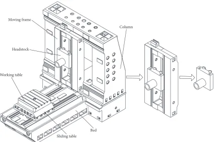
Bed
Column
Sliding table Working table
Moving frame
[image:3.600.89.514.71.352.2]Headstock
Figure 1: Configuration of a high speed precision horizontal machining center.
process, more than 50% of the cutting point deflection of machine tool structures comes from the headstock, with the remainder coming from beds, slides, and joint interfaces [3, 5]. Therefore, to improve the cutting performance of machine tool, the headstock of high dynamic stiffness is essential. Since the dynamic stiffness is proportional to the damping, a high damping property is an effective way to improve the dynamic stiffness.
For the structures like plates, shells, and boxes, Constrai-ned Layer Damping (CLD) structure is an effective way to improve damping property. This structure was firstly studied by Kerwin [6], who developed a simplified theory relating the shear strain of the damping layer to the transverse motion of the structure. Thereafter numerous theoretical analyses of simple sandwich beam and plate structure were published based on the laminate theories by Ross et al. [7] and Mead and Markus [8]. Johnson and Kienholz [9] proposed an efficient method to describe complicated damping structure that modal damping ratios were estimated from undamped normal mode result by means of Modal Strain Energy (MSE) method. Good agreement of natural frequency and modal loss factor was obtained by comparing MSE method with classic complex stiffness eigenvalue method.
Full coverage passive CLD treatments are not applicable in many cases. Lall [10, 11] attempted to analyze a partially covered sandwich beam and plate and developed two for-mulations based on simplified methods, while the other one based on an exact method. Marcelin et al. [12] investigated the optimal damping of beams partially covered by constrained viscoelastic layers using a genetic algorithm, wherein the
design variables were the dimensions and locations of the viscoelastic layers and the objective function was the max-imum damping factor. Alvelid [13] optimized the position and shape of attached passive CLD using a modified gradient method, the objective of which was the minimum value of frequency averaged transverse vibration levels of a plate with a harmonic excitation. Lepoittevin and Kress [14] presented a new approach for finding optimum damping treatment by sectioning the constraining and constrained layers, and the loss factor for a given mode improved between 48% and 92% compared to a full coverage configuration. Guo et al. [15] studied the problem of topological optimization design for simple CLD plate on the basis of Evolutionary Structural Optimization (ESO) method. This method has certain significance on the optimization design of damping structure and has extensive application prospect in engineer-ing. Fang and Zheng [16] proposed a topology optimization by ESO method to minimize the resonant response of plates with CLD treatment under specified broadband harmonic excitations. Kim et al. [17] designed an optimal damping layout of an unconstrained-layer shell structure by employ-ing the modal shape, the strain energy distribution, and the topology optimization methods, and it was found that topology optimization provides a higher modal loss factor. These topology methods are proved practical for the simple plates or shells, but there are few application examples for the complicated structure.
Base layer (elastic layer) Viscoelastic layer (damping layer)
[image:4.600.84.259.73.142.2]Constraining layer
Figure 2: CLD structure.
structure is adhered to the surface of headstock. MSE method is employed for the modeling of the damping structure. In order to achieve the best performance, ESO topology method is implemented and an improved sensitivity is proposed for the optimization of the CLD structure.
2. Methods of Modeling and Topology
Optimization of CLD Structure
2.1. Modeling of CLD Structure. Complex eigenvalue, direct
[image:4.600.359.546.367.473.2]frequency response and MSE method are generally used in dynamic analysis of composite damping structure. The calculation of the first two methods is in complex domain. Thus, the cost will be extremely high when calculating complex structure. The MSE method is from the point of view of the energy, and the loss factor of structure is defined as the ratio of dissipation energy and total deformation energy. The damping capacity increases with the increase of the loss factor. The parameters of damping structure can be expediently analyzed and optimized using this method in the finite element analysis. Hence, the MSE method will be employed in this paper. The CLD structure is shown in Figure 2.
The strain energy of base layer𝑈𝑝, viscoelastic layer𝑈V,
constraining layer𝑈𝑐, and composite structure𝑈are,
respec-tively, expressed as
𝑈𝑝= 1
2{Φ}𝑇[𝐾]𝑝{Φ} (1)
𝑈V= 1
2{Φ}𝑇[𝐾]V{Φ} (2)
𝑈𝑐= 12{Φ}𝑇[𝐾]𝑐{Φ} (3)
𝑈 = 1
2{Φ}𝑇[𝐾] {Φ} , (4)
where{Φ}is real vector of the associated undamped system
and[𝐾]𝑝,[𝐾]V,[𝐾]𝑐, and[𝐾]are the stiffness matrix of base
layer, viscoelastic layer, constraining layer, and the composite structure, respectively; their relationship can be expressed by
[𝐾] = [𝐾]𝑝+ [𝐾]V+ [𝐾]𝑐. (5)
The energy dissipation of damping material in a cycle𝑊
can be expressed as
𝑊 = 1
2𝛽 {Φ}𝑇[𝐾]V{Φ} . (6)
Then, the loss factor of composite structure𝜂is obtained
as
𝜂 = 𝑊𝑈 =𝑈 𝛽𝑈V
𝑝+ 𝑈V+ 𝑈𝑐. (7)
2.2. Topology Optimization of CLD Structure. In order to
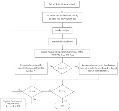
achieve the best performance of a CLD structure considering various constraints such as lightweight and low-cost, the shape and layout of damping material should be optimized in the design domains. Topology optimization is a good solution for this problem. The ESO method, one of design methods of topology optimization based on the simple concept of gradually removing inefficient material from structure, is extensively employed. As a numerical method based on finite element analysis where the design domain is discretized into the fine mesh of elements, the optimization procedure is to find every point whether there should be material (solid element) or not (void element). The ESO method is suitable for a wide range of structure design problems and easily implemented in finite element analysis software. With the removal rate of damping material being the constraint and the maximum weighted value of the damping factor being the objective, the model for damping optimization of CLD structure can be shown as follows:
Find 𝑒 = [𝑒1, 𝑒2, 𝑒3, . . . , 𝑒𝑛]𝑇
Max 𝜂 =
𝑘 ∑
𝑟=1𝑤𝑟𝜂𝑟
𝑘 ∑
𝑟=1𝑤𝑟= 1
s.t. 𝑉 =
𝑁 ∑ 𝑖=1
𝑒𝑖V𝑖≤ 𝑉𝑡 𝑒𝑖= {0, 1}
𝜔𝑟 ≥ 𝜔∗𝑟,
(8)
where𝑒is the optimization variable,𝑒𝑖stands for the state of
𝑖th element of damping layer,𝑒𝑖 = 0stands for the element
being dead,𝑒𝑖= 1stands for the element being alive,V𝑖is the
volume of the𝑖th element,𝑉𝑡is the maximum design
allow-able value of the volume for the damping material,𝜂𝑟stands
for the𝑟th modal loss factor,𝑤𝑟is the corresponding weight
coefficient,𝜔𝑟is the𝑟th natural frequency, and𝜔𝑟∗stands for
the minimum design allowable value of the 𝑟th natural
frequency.
In the finite element analysis, dynamics eigenvalue equa-tion of the undamped structure is expressed as
([𝐾] − 𝜔𝑟[𝑀]) {Φ𝑟} = 0, (9)
where[𝐾]is the stiffness matrix of the structure,[𝑀]is the
mass matrix of the structure, andΦ𝑟is the eigenvector of the
𝑟th natural frequency
According to the MSE method, the𝑟th modal loss factor
of composite structure can be obtained from the energy distribution in the structure by
𝜂𝑟 =𝛽𝑈𝑟V
𝑈𝑟 =
𝛽𝑈𝑟V
where𝑈𝑟𝑏,𝑈𝑟V,𝑈𝑟𝑐, and𝑈𝑟are the strain energy of base layer, viscoelastic layer, constraining layer, and the whole structure
in the considered mode𝑟, respectively.
In the finite element analysis, when the 𝑖th element of
damping layer is removed, the corresponding element of constraining layer at the same location is also removed. The
variation of the𝑟th modal loss factor of composite structure
is [15]
Δ𝜂𝑟 = 𝛽 (Δ𝑈𝑟V
𝑈𝑟 −
Δ𝑈𝑟𝑈𝑟V
𝑈𝑟2 ) . (11)
In the process of iteration, because the number of remo-ved elements every time is constrained, the change of
struc-ture is extremely small. Assume that the real vector{Φ}is
nearly the same after the𝑖th element is removed, during the
process of optimization, the modal shape is considered as consistent in the two-iteration step. Thus, the variation of strain energy of damping layer can be considered as
Δ𝑈𝑟V≈ 1
2{Φ𝑟}
𝑇[Δ𝐾] {Φ
𝑟} = −12{𝜑𝑟𝑖}𝑇[𝐾𝑖] {𝜑𝑟𝑖}
= −𝑈𝑟V𝑖,
(12)
where[𝐾𝑖]is the stiffness matrix of the𝑖th element of the
vis-coelastic layer,{𝜑𝑟𝑖}is the eigenvector of the𝑖th element in
the𝑟th natural frequency, and𝑈𝑟V𝑖is the strain energy of the
𝑖th element of viscoelastic layer in the considered mode𝑟.
Similarly, the variation of strain energy of the whole structure is
Δ𝑈𝑟≈ − (𝑈𝑟V𝑖+ 𝑈𝑟𝑐𝑖) , (13)
where𝑈𝑟𝑐𝑖is the strain energy of the𝑖th element of
constrain-ing layer in the considered mode𝑟.
Substituting (12) and (13) into (11) yields
Δ𝜂𝑟 = 𝑈𝛽
𝑟 (
(𝑈𝑟V𝑖+ 𝑈𝑟𝑐𝑖) 𝑈𝑟V
𝑈𝑟 − 𝑈𝑟V𝑖) , (14)
whereΔ𝜂𝑟is the variation of the𝑟th modal loss factor on the
𝑖th element of damping layer.
The size of the element cannot be consistent in the mesh process of the composite structure. Thus, the sensitivity of
optimization is defined as the variation of the𝑟th modal loss
factor on the per unit volume of the𝑖th element of damping
layer, which can be expressed as
𝛼𝑟𝑖= Δ𝜂V𝑟𝑖
𝑖 . (15)
Substituting (15) into (14) yields
𝛼𝑟𝑖= V𝛽
𝑖𝑈𝑟(
(𝑈𝑟V𝑖+ 𝑈𝑟𝑐𝑖) 𝑈𝑟V
𝑈𝑟 − 𝑈𝑟V𝑖) . (16)
The strain energy of the element can easily be obtained in the finite element analysis. Using ANSYS parametric design
Table 1: Mechanical property of each material.
Density (kg/m3) Modulus (GPa) Poisson’s ratio Viscoelastic
material 1100 0.009 0.49
[image:5.600.310.548.89.141.2]Aluminum 2700 70 0.3
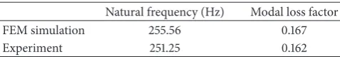
Table 2: Comparison of FEM simulation and experiment.
Natural frequency (Hz) Modal loss factor
FEM simulation 255.56 0.167
Experiment 251.25 0.162
language, a program is compiled to finish topology opti-mization. The flow chart of topology optimization process by ANSYS is shown as in Figure 3.
2.3. Experiment Verification of MSE Method. In order to
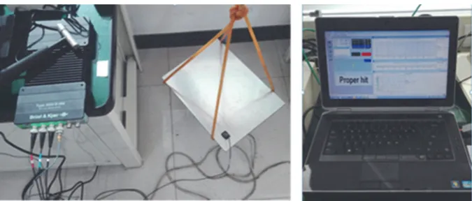
verify the effectiveness of the MSE method, a plate composite specimen is manufactured and tested to measure the loss factor, as shown in Figure 4. The length and width of all layers are 400 mm and 300 mm, respectively, and the thickne-sses of base layer, damping layer, and constraining layer are 4 mm, 2 mm, and 2 mm, respectively. The base layer and constraining layer are made of aluminum, and the mechanical properties of each material are listed in Table 1. The exciting force is applied at point 1, and the output signal is picked up at point 2.
The loss factor and natural frequency were tested by the impulse-frequency response test. The testing apparatus con-sisted of an input module (B&K 3050), an impulse hammer (B&K 8206), and an accelerometer (B&K 4506). A force transducer is integrated on the hammer. Natural frequency and loss factor were measured by giving impulses on the specimen suspended with thin strings as shown in Figure 5. The loss factor was calculated by the half power band width method as follows:
𝜂 = 𝑓2𝑓− 𝑓1
𝑟 , (17)
where𝑓𝑟is the resonant frequency,𝑓1is the left side
freque-ncy of the half power band, and𝑓2is the right side frequency
of the half power band.
[image:5.600.309.548.181.221.2]Set up finite element model
Sensitivity calculation Modal analysis
End Yes
No
Yes No
Yes No Set initial material remove rateR0
and the rate of evolutionER
Search maximum and minimum value of the
sensitivity𝛼maxand𝛼min
Remove elements with
number N1
sensitivity𝛼max; extract the 𝛼max> 0
N > 0 V⩽Vt
Update the material removal rate
Ri+1= Ri+ ER
Remove elements with the absolute
value of sensitivity less thanRi∗ |𝛼min|;
[image:6.600.100.502.71.445.2]extract the number N2
Figure 3: Flow chart of topology optimization process by ANSYS.
Point 1
Point 2 Exciting force
(a) The sketch (b) The finite element model
Figure 4: Flat panel sample.
3. Simulation of Headstock with
Damping Material
3.1. Dynamic Analysis of the Original Headstock with
Con-straint. To estimate the dynamic characteristics of the
origi-nal headstock, finite element aorigi-nalysis is performed by treating spindle and headstock as a unified whole. The headstock
is made of cray iron. Young’s modulus, density, and
Pois-son’s ratio are 178 GPa, 7450 kg/m3, and 0.3, respectively. To
simulate the actual constraint state, the headstock is
con-strained with𝑌direction freedom at the position connected
with screw nuts, with 𝑋 and 𝑍 direction freedoms at the
[image:6.600.140.458.491.617.2]Figure 5: The specimen and test system.
210 220 230 240 250 260 270 280 290 300 200
Frequency (Hz) 0
0.2 0.4 0.6 0.8 1
Res
p
o
n
[image:7.600.342.513.283.499.2]se
Figure 6: The frequency-domain response.
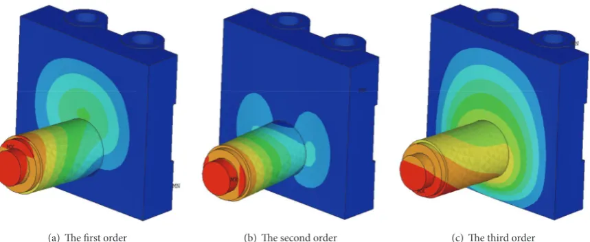
[image:7.600.61.284.283.507.2]The modal analysis is performed, with the first three-order frequencies being 386.91 Hz, 387.99 Hz, and 666.60 Hz, respectively. Since the headstock is approximate symmetry, the values of the first and second frequencies are close. The modal shapes are shown in Figure 8. At the first- and second-order natural frequencies, the cylinder part swings in the vertical and horizontal direction, respectively. At the third order, the front face contacted with the cylinder part twist forward and backward. To obtain the frequency response, harmonic response analysis with mode superpo-sition method is performed. A harmonic exciting force of 0 to 1000 Hz is applied at the position connected with tool nose. The simulation results show that the response amplitude of first and second-order frequency is evidently greater than others. Thus, the optimization objective of added damping structure focus on the first and second modal loss factor.
Figure 7: Finite element model of headstock with constraint.
3.2. Dynamic Analysis of the Hybrid Headstock with
Con-straint. To improve the damping capacity, a plate which
(a) The first order (b) The second order (c) The third order
Figure 8: Modal shapes of the first three-order frequencies.
Headstock Constraining layer
Damping layer
[image:8.600.157.441.292.406.2]+
Figure 9: Hybrid headstock with damping material.
370 380 390
-Resp
o
n
se
(m)
Original structure
Damping layer 3mm, constraining layer 3mm Damping layer 5mm, constraining layer 3mm Damping layer 5mm, constraining layer 5mm Damping layer 7mm, constraining layer 5mm
900
100 200 300 400 500 600 700 800 1000
0
Frequency (Hz)
10−3
10−4
10−4
10−5
10−6
Figure 10: Response of structure with different thickness.
The modal analysis is performed, with the first three-order natural frequencies being 380.66 Hz, 386.88 Hz, and 658.62 Hz, respectively. Compared to original structure, the natural frequencies almost unchanged. The first three-order modal loss factor is calculated by MSE method, with the values of 0.437%, 0.421%, and 0.194%. Harmonic response analysis with mode superposition method is performed, and
the response curve is shown as in Figure 11. It can be seen that the response amplitude of hybrid headstock decreased obviously compared to the original structure. Thus, the treatment with damping material is effective and feasible to improve the damping capacity of the headstock.
4. Experiment Verification of Headstock with
Damping Material
4.1. Experiment Set and Methods. A headstock specimen
is prepared and the vibration responses are measured in order to verify the effectiveness of the damping material. The testing apparatus consists of an input module (B&K 3050), an impulse hammer (B&K 8206), and an accelerometer (B&K 4506). Because the actual supports and fixations of the headstock in working situation are hardly realized, free support is selected here. The headstock is freely suspended by a rubber rope. The frequency response of the headstock is tested as shown in Figure 12.
[image:8.600.53.288.453.622.2]Original structure Damping structure
R
es
p
ons
e of
X
dir
ec
tio
n
((m/s
2)/N)
400 600 800 1000
200
Frequency (Hz)
10−4
10−3
10−2
10−1
100
101
102
(a) Frequency response of𝑋direction
Original structure Damping structure
400 600 800 1000
200
Frequency (Hz)
10−4
10−3
10−2
10−1
100
101
102
R
es
p
ons
e of
Y
dir
ec
tio
n
((m/s
2 )/N)
(b) Frequency response of𝑌direction
Original structure Damping structure
400 600 800 1000
200
Frequency (Hz)
10−5
10−4
10−3
10−2
10−1
100
101
102
R
es
p
ons
e of
Z
dir
ec
tio
n
((m/s
2 )/N)
(c) Frequency response of𝑍direction
Figure 11: Frequency response of headstock with damping material and original structure.
BK input module
Computer (BK test.lab)
Impulse hammer
Acceleration sensor
[image:9.600.176.422.631.723.2]Headstock Elastic string
Accelerometer Original structure Rubber rope Damping structure
[image:10.600.156.442.72.292.2]Impulse hammer Input module
Figure 13: Experiment setup of the headstock.
Secondly, the damping layer and the constraining layer are adhesively bonded to the surface of the headstock by epoxy resin adhesive. Lastly, the frequency response of the hybrid headstock is tested as shown in Figure 13.
4.2. Discussion of Experiment Results. The frequency
res-ponse curves in three directions between original and hybrid
headstock are shown in Figure 14. In the𝑋and𝑌direction,
the response amplitude of the first-order natural frequency
is largest. In the𝑍 direction, the largest amplitude occurs
at the second-order natural frequency. The values of natural frequency and response amplitude by experiment of two structures are shown in Table 3. Compared with two struc-tures, it can be seen that there is little variation of the natural frequency, but the damping material can significantly reduce the peak response at the natural frequency. The response amplitude of three directions decreases by 86%, 63%, and 82%, respectively. The results indicate that the effectiveness of the damping material is satisfactory.
5. Topology Optimization of CLD
Structure for the Headstock
In the damping treatment applications to the headstock or other basic large components of the machine tool, full coverage CLD treatments are evidently not practical. First of all, some small components are needed to be assembled on the surface of these components. Secondly, according to the distribution of strain energy shown as in Figure 15, only some parts of viscoelastic material play a main role to the damping capacity. Thirdly, full coverage treatment adds excessive mass to the structure and influences the static and dynamic properties. In this section, topology optimization is implemented to achieve best performance with the constraint of material removal rate and natural frequency. For the
response amplitude of first- and second-order frequencies is evidently greater than others, the maximum weighted modal loss factor is selected to be the objective, which is defined by
𝜂 = 0.5𝜂1+ 0.5𝜂2. When the material removal rate is limited
to 50%, the model for topology optimization can be shown as follows:
Find 𝑒 = [𝑒1, 𝑒2, 𝑒3, . . . , 𝑒𝑛]𝑇
Max 𝜂 = 0.5𝜂1+ 0.5𝜂2
s.t. 𝑉 =
𝑁 ∑ 𝑖=1
𝑒𝑖V𝑖≤ 0.5𝑉0 𝑒𝑖= {0, 1} .
(18)
A program is compiled to finish topology optimization using ANSYS parametric design language. The optimization result is shown in Figure 16, where the blue color stands for the removal elements and the red color stands for the reserved elements. It can be seen that the reserved parts agree well with distribution of strain energy.
Original structure Damping structure
R
es
p
ons
e of
X
dir
ec
tio
n
((m/s
2)/N)
10−3
10−2
10−1
100
101
102
700 900 1100 1300 1500
500
Frequency (Hz)
(a)𝑋direction of experiment
Original structure Damping structure
10−3
10−2
10−1
100
101
102
R
es
p
ons
e of
Y
dir
ec
tio
n
((m/s
2 )/N)
700 900 1100 1300 1500
500
Frequency (Hz)
(b)𝑌direction of experiment
Original structure Damping structure
10−3
10−2
10−1
100
101
102
R
es
p
ons
e of
Z
dir
ec
tio
n
((m/s
2 )/N)
700 900 1100 1300 1500
500
Frequency (Hz)
(c) 𝑍direction of experiment
[image:11.600.57.548.666.731.2]Figure 14: Experiment frequency response curve of the headstock.
Table 3: Comparison of natural frequency and response amplitude for two structures.
Natural frequency (Hz) Response amplitude ((m/s2)/N)
1st 2nd 3rd 𝑋direction 𝑌direction 𝑍direction
Original structure 852 863 1133 55 14.0 16.5
Hybrid structure 846 861 1123 7.8 5.2 3.0
0 1 2 5 10 25 50 100 200
(a) The first order
0 1 2 5 10 25 50 100 200
(b) The second order
0 1 2 5 10 25 50 100 200
MN
[image:12.600.121.481.72.475.2](c) The third order
Figure 15: Modal Strain Energy distribution of damping plate.
Table 4: Comparison of natural frequency and modal loss factor for two structures.
Natural frequency (Hz) Modal loss factor (%)
1st 2nd 3rd 1st 2nd 3rd
Full coverage 380.66 386.88 658.62 0.437 0.421 0.194
Topo results 380.37 386.61 658.73 0.355 0.322 0.191
Change rate 0.01% 0.01% 0.01% 18.8% 23.5% 1.5%
result. And this result can guide the design of the headstock. For instance, the threaded hole and the oil hole should be arranged at the area without the damping material.
6. Conclusion
To improve the damping capacity, a hybrid headstock is desig-ned by adhesively bonding a damping layer and constraining layer to the surface of the cast headstock. For such complex
damping structure, it can be expediently analyzed using MSE method. The dynamic characteristic of the hybrid headstock is investigated analytically and experimentally. It is found that the response amplitudes of hybrid headstock in three direc-tions decrease by 86%, 63%, and 82% than those of the ori-ginal cast one.
[image:12.600.50.553.539.603.2](a) Removal rate 20% (b) Removal rate 30%
[image:13.600.126.479.73.320.2](c) Removal rate 40% (d) Removal rate 50%
Figure 16: Optimization result with material.
0 10 20 30 40 50 60
Remo
val ra
te
(%)
20 40 60 80 100 120 140 160 180 200
0
[image:13.600.55.284.374.483.2]Iteration number
Figure 17: Iteration histories of removal rate.
First order Second order Third order
×10−3
0 0.5 1.0 1.5 2.0 2.5 3.0 3.5 4.0 4.5 5.0
L
o
ss fac
to
r
0 10 20 30 40 50 60
Removal rate (%)
Figure 18: Change of the modal loss factor with the removal rate.
loss factor. The optimization results indicate that the added weight of damping material decreases by 50%, and the first
two orders of modal loss factor decrease by less than 23.5% compared to the original full cover structure.
Competing Interests
All the authors declare that there is no conflict of interests regarding the publication of this paper.
Acknowledgments
This research project is supported by the State S&T Projects for Upmarket NC Machine and Fundamental Manufacturing Equipment of China (nos. 2013ZX04005-013, 2014ZX04014-011, 2015ZX04005-001, and 2016ZX04004-002, resp.).
References
[1] J.-H. Kim and S.-H. Chang, “Design of𝜇-CNC machining cen-tre with carbon/epoxy composite–aluminium hybrid structures containing friction layers for high damping capacity,”Composite Structures, vol. 92, no. 9, pp. 2128–2136, 2010.
[2] A. Rashid and C. M. Nicolescu, “Design and implementation of tuned viscoelastic dampers for vibration control in milling,”
International Journal of Machine Tools & Manufacture, vol. 48, no. 9, pp. 1036–1053, 2008.
[3] S. H. Chang, P. J. Kim, D. G. Lee, and J. K. Choi, “Steel-com-posite hybrid headstock for high-precision grinding machines,”
Composite Structures, vol. 53, no. 1, pp. 1–8, 2001.
[image:13.600.57.283.511.669.2][5] F. P. Wardle, S. J. Lacey, and S. Y. Poon, “Dynamic and static cha-racteristics of a wide speed range machine tool spindle,”
Precision Engineering, vol. 5, no. 4, pp. 175–183, 1983.
[6] E. M. Kerwin, “Damping of flexural waves by a constrained vis-coelastic layer,”Journal of the Acoustical Society of America, vol. 31, no. 7, pp. 952–962, 1959.
[7] R. Ross, E. E. Ungar, and E. M. Kerwin, “Damping of plate of fle-xural vibrations by means of viscoelastic laminate,” in Proceed-ings of the Structural Damping—A Colloquium on Structural Damping Held at the ASME Annual Meeting, pp. 49–88, 1959. [8] D. J. Mead and S. Markus, “The forced vibration of a three-layer,
damped sandwich beam with arbitrary boundary conditions,”
Journal of Sound and Vibration, vol. 10, no. 2, pp. 163–175, 1969. [9] C. D. Johnson and D. A. Kienholz, “Finite element prediction of damping in structures with constrained viscoelastic layers,”
AIAA journal, vol. 20, no. 9, pp. 1284–1290, 1982.
[10] A. K. Lall, N. T. Asnani, and B. C. Nakra, “Vibration and damp-ing analysis of rectangular plate with partially covered con-strained viscoelastic layer,”Journal of vibration, acoustics, stress, and reliability in design, vol. 109, no. 3, pp. 241–247, 1987. [11] A. K. Lall, N. T. Asnani, and B. C. Nakra, “Damping analysis of
partially covered sandwich beams,”Journal of Sound and Vibra-tion, vol. 123, no. 2, pp. 247–259, 1988.
[12] J.-L. Marcelin, S. Shakhesi, and F. Pourroy, “Optimal constrai-ned layer damping of beams: experimental and numerical studies,”Shock & Vibration, vol. 2, no. 6, pp. 445–450, 1995. [13] M. Alvelid, “Optimal position and shape of applied damping
material,”Journal of Sound and Vibration, vol. 310, no. 4-5, pp. 947–965, 2008.
[14] G. Lepoittevin and G. Kress, “Optimization of segmented con-strained layer damping with mathematical programming using strain energy analysis and modal data,”Materials and Design, vol. 31, no. 1, pp. 14–24, 2010.
[15] Z. Z. Guo, Y. Z. Chen, K. W. Deng, and Q. Hou, “Study on topo-logical optimization design of constrained damping plate based on evolutionary structural optimization,”Journal of Machine Design, vol. 23, no. 10, pp. 3–5, 2006.
[16] Z. Fang and L. Zheng, “Topology optimization for minimizing the resonant response of plates with constrained layer damping treatment,”Shock and Vibration, vol. 2015, Article ID 376854, 11 pages, 2015.
International Journal of
Aerospace
Engineering
Hindawi Publishing Corporation
http://www.hindawi.com Volume 2014
Robotics
Journal of Hindawi Publishing Corporationhttp://www.hindawi.com Volume 2014
Hindawi Publishing Corporation
http://www.hindawi.com Volume 2014
Active and Passive Electronic Components
Control Science and Engineering Journal of
Hindawi Publishing Corporation
http://www.hindawi.com Volume 2014
Machinery
Hindawi Publishing Corporation
http://www.hindawi.com Volume 2014
Hindawi Publishing Corporation http://www.hindawi.com
Journal of
Engineering
Volume 2014
Submit your manuscripts at
https://www.hindawi.com
VLSI Design
Hindawi Publishing Corporation
http://www.hindawi.com Volume 2014
Hindawi Publishing Corporation
http://www.hindawi.com Volume 2014
Shock and Vibration Hindawi Publishing Corporation
http://www.hindawi.com Volume 2014
Civil Engineering
Advances inAcoustics and VibrationAdvances in
Hindawi Publishing Corporation
http://www.hindawi.com Volume 2014
Hindawi Publishing Corporation
http://www.hindawi.com Volume 2014
Electrical and Computer Engineering
Journal of
Advances in OptoElectronics
Hindawi Publishing Corporation
http://www.hindawi.com Volume 2014
The Scientific
World Journal
Hindawi Publishing Corporation
http://www.hindawi.com Volume 2014
Sensors
Journal ofHindawi Publishing Corporation
http://www.hindawi.com Volume 2014
Modelling & Simulation in Engineering
Hindawi Publishing Corporation
http://www.hindawi.com Volume 2014
Hindawi Publishing Corporation
http://www.hindawi.com Volume 2014
Chemical Engineering
International Journal of Antennas and
Propagation
International Journal of
Hindawi Publishing Corporation
http://www.hindawi.com Volume 2014
Hindawi Publishing Corporation
http://www.hindawi.com Volume 2014
Navigation and Observation International Journal of
Hindawi Publishing Corporation
http://www.hindawi.com Volume 2014