warwick.ac.uk/lib-publications
Original citation:
Yuan, T., Jin, Y., Guo, Weisi, Fang, C., Deng, W. and Wang, Tao. (2016) Low-complexity
energy-efficient resource allocation for delay-tolerant two-way orthogonal
frequency-division multiplexing relays. IET Communications, 10 (17). 2488 -2495.
http://doi.org/10.1049/iet-com.2015.1075
Permanent WRAP URL:
http://wrap.warwick.ac.uk/93670
Copyright and reuse:
The Warwick Research Archive Portal (WRAP) makes this work by researchers of the
University of Warwick available open access under the following conditions. Copyright ©
and all moral rights to the version of the paper presented here belong to the individual
author(s) and/or other copyright owners. To the extent reasonable and practicable the
material made available in WRAP has been checked for eligibility before being made
available.
Copies of full items can be used for personal research or study, educational, or not-for-profit
purposes without prior permission or charge. Provided that the authors, title and full
bibliographic details are credited, a hyperlink and/or URL is given for the original metadata
page and the content is not changed in any way.
Publisher’s statement:
"This paper is a postprint of a paper submitted to and accepted for publication in IET
Communications and is subject to Institution of Engineering and Technology Copyright. The
copy of record is available at IET Digital Library"
A note on versions:
The version presented here may differ from the published version or, version of record, if
you wish to cite this item you are advised to consult the publisher’s version. Please see the
‘permanent WRAP URL’ above for details on accessing the published version and note that
access may require a subscription.
Abstract—Energy-efficient wireless communication is becoming increasingly important, especially for wireless devices with a limited battery life and cannot be recharged on a frequent basis. In this paper, a bit allocation algorithm to minimize the total energy consumption for transmitting a bit successfully is proposed for a two-way orthogonal frequency-division multiplexing (OFDM) relay system, whilst considering the constraints of quality-of-service (QoS) and total transmit power. Our scenario is fit for the delay-tolerant services delivered through low-complexity devices in application areas of IoT and M2M communications. Unlike existing bit allocation schemes, which maximize the energy efficiency by measuring “bits-per-Joule” with fixed bidirectional total bit rates constraint and no power limitation, our scheme adapts the bidirectional total bit rates and their allocation on each subcarrier with a total transmit power constraint.
In order to do so, we propose a new idea to decompose the optimization problem. The problem is solved in two general steps. The first step allocates the bit rates on each subcarrier when the total bit rate of each user is fixed. In the second step, the Lagrangian multipliers are used as the optimization variants, andthe dimension of the variant optimization is reduced from 2N to 2, where N is the number of subcarriers. We also prove that the optimal point is on the bounds of the feasible region, thus the optimal solution could be searched through the bounds. The dimension of the variant optimization can be further reduced to 1 by variant substitution when searching through each bound, which significantly reduces the complexity of the proposed algorithm. Simulations are conducted to evaluate the transmit energy efficiency (EE) and spectral efficiency (SE), which demonstrate an average improvement of EE of about 200% over the current non-optimized systems.
Index Terms—Energy efficiency, bit allocation, two-way relay, orthogonal frequency-division multiplexing
(OFDM), low complexity, machine-to-machine (M2)
I. INTRODUCTION
Increasing demand for wireless capacity growth in the past several years has led to growing research
in energy efficiency and sustainability. For small devices and sensors, which make up the bulk of the 6
billion connected Internet-of-Things (IoT), the mains supply is typically not available and their battery
cannot be easily replaced or recharged on a frequent basis [1]. It is likely that these low powered IoT devices will communicate via relays to a local hub, and the Energy efficiency (EE) becomes an important metric. EE can be evaluated by the total energy consumption per successfully received message (Joules-per-bit). In general, research is typically focused on minimizing the joule per bit [2],
[3], or maximizing bits-per-Joule [4], [5]. However, there is greater opportunity in IoT devices to
Low-Complexity Energy-Efficient Resource Allocation for
Delay-Tolerant Two-Way OFDM Relays
Tiantian Yu1, Yanliang Jin1, Weisi Guo2, Changli Fang1, Wei Deng1, and Tao Wang1
, Senior Member, IEEE
1
improve energy efficiency than in cellular radio, due to the delay-tolerant nature of the data. Yet, the
devices are relatively simple and cannot perform complex signal processing algorithms. Therefore, the
EE optimization algorithms developed need to be low complexity.
In orthogonal frequency-division multiplexing (OFDM), frequency selective fading can be
effectively combated and high spectral efficiency can be achieved. This is why OFDM serves as an
essential technique in the current and next generation mobile communications. Multiple relay-based
OFDM systems have been proposed under LTE-A and IEEE 802.16 due to its potential to enhance
throughput and extend coverage [6]. A number of important relay protocols have already been proposed
in the past decade, such as the amplify-and-forward (AF) and decode-and-forward (DF) protocols
[7]-[10]. Since the development of physical-layer network coding [11], research has gone to investigate
this topic further [12]-[15] to show system throughput improvements of over 100%. Therefore, in this
paper, we will investigate a two-way relay OFDM system using the AF protocol. Previous work has
largely focused on the optimization for spectral efficiency (SE) [16-18], however, the optimal point of
SE is not necessarily equivalent to that of EE [19], so the optimization of EE under different scenarios
is another significant problem we should consider. In the past, EE optimization of direct links was analyzed in [4] and [20]. In [4], the EE is optimized in frequency-selective channels using
multi-carriers, where the constraints of sum rate and total power consumption including circuit power
were considered. In [20], the downlink and uplink of orthogonal frequency-division multiplexing
access (OFDMA) networks with QoS and fairness issues were considered. Yet, we know that the methods that allocate resources to optimize EE in direct links are not the same as those relay based
links. The reason lies in the differences of system models and the types of resource available to allocate.
Whilst SE and EE optimization for relay deployment has been examined recently [21], limited work
has been done to address EE optimization for relay based communication on the radio resource
allocation level (see [5] for one/two-way relaying in OFDM systems).
For real time services [23], existing work in [5, 22] have analyzed the optimal EE is acquired under the QoS and symbol error rate with multiple relays. Real-time services [23] constrains a sum rate for individual users, which is not required in delay tolerant services, where only minimum rate requirements are needed for each user. Due to the fixed bidirectional total bit rates constraints, the
methods of [5] and [22] to allocate resources are not suitable in delay-tolerant services. Another
problem in [5] and [22] is that transmit power consumption is not limited, which makes it hard to use
those corresponding methods in low power situations. Other related work includes [24-26], but none of them have considered QoS requirements.
In our paper, we consider the QoS requirements in the form of delay-tolerant data demand and total
power restrictions, which to the best of our knowledge has not been considered before. In order to
reduce the complexity of the algorithm, we introduce a new idea to reduce the dimension of the
variants, which resolves the optimization problem in two steps and is achieved by looking at the
Lagrangian multipliers as the optimization variants. To the best of our knowledge, this also hasn’t been
studied before. The rest of the paper is organized as follows. In Section II, a two-way OFDM relay
system model is presented. In Section III, the EE optimization problem is formulated. The
low-complexity algorithm for resource allocation is proposed in section IV. In section V, simulation
II. SYSTEMMODEL
(a) Multiple-access phase: nodes A, B transmit information bits simultaneously to relay R.
(b) Broadcast phase: relay R broadcasts the processed information to nodes A and B.
Fig.1. Multiple access and broadcast process, the total duration time is 2T, and channel reciprocity is assumed. We consider a two-way OFDM relay system consisting of three nodes. The two source nodes A and
B exchange information bi-directionally with N subcarriers through the AF relay R. Each node is
equipped with a single antenna, and the system works at the half-duplex mode. Assume the signal
between two source nodes is severely attenuated, therefore, the direct link is not considered. The
transmission process is composed of two phases: a multiple-access (MA) phase and a broadcast (BC)
phase, as illustrated in Fig.1. The time duration of the two phases is the same, donated as T. In the MA
phase, nodes A and B simultaneously transmit information bits to the relay node R. The two signals
along with the noise are superimposed first, and then amplified in relay R. In the BC phase, relay R
broadcasts the processed signal to the nodes A and B.
Whilst the majority of papers assume that the channel state information (CSI) is perfect, we know
that in practice, the CSI is not perfect, which makes it hard to find an explicit expression of the system
EE. As shown in Fig.1, the channel coefficients of MA and BC phases are the same, which is true when
the system works at the time division duplex (TDD) mode, where channel reciprocity applies. The
channel is considered to be block fading, and the channel coefficients are constant during the time
duration 2T, meaning the channel gain is constant during one complete communication cycle.
The total operational energy consumption consists of two parts: transmit power consumption
(radio-head) and circuit power consumption (over-head) [27]. We ignore the overhead circuit power
consumption, due to the fact that it scales in complex ways with data throughput, and the complexity is
dependent on specific hardware technologies that we wish to avoid becoming sensitive to. We want to
focus on the bit error rate and its direct relationship to the transmit power of the signal. Based on the
consideration, we will omit the circuit power consumption. Therefore, the EE can be expressed as
2 (1)
( ) 2
,
EE
ab ba ab ba T
T TP
B B T B B
P
where T is the duration of one phase (MA or BC), the factor of 2 is due to the half-duplex bidirectional communication. PT is the overall transmit power consumption.
B
ab andB
baare respectively the sum message bits transmitted in AB direction and BA direction in one complete transmission. Note that the denominator of the first fraction in (1) represents the sum rate of the system.thus
B
ab andB
ba can be formulated as:1
1
(2a)
(2b)
,
.
N i ab ab
i N
i ba ba
i
B
B
B
B
Many OFDM systems fix T as a constant, and we conform to this setting. We should nevertheless point out that T can also be taken as an optimization variant [29], which leads to a better performance system. The approximate minimum total transmit power of the three nodes on the thi subcarrier can be derived as [5], [29]:
min
/ /
0 0
2 2 )
(
)
(2
1)
(2
1)
(3
2 |
|
2 |
|
,
i i i
i i
ab ba
i
t t t a b r
B B
TW N TW N
i i
eff eff
t
P
P
P
P
N
N
h
h
where | | 1 / ( 1 1 ) | | | | i
eff i i
ar br
h
h h
( A B means that A is defined as B) can be viewed as an effective
channel gain on the thi subcarrier between the two source nodes due to the usage of the relay, W is the bandwidth of nodes A and B . The approximate expression of (3) comes from the approximation
2
/1
2
/.
(4)i i
ab ab
B B
TW N
TW NThe approximation above is relatively accurate in high SE region (i.e. Babi / (TW)is large), which is nearly established in low SE region when N is not too small. With the approximation, we can simplify the derivation process, so (3) is used in this paper to calculate the transmit power. The overall transmit powerPTtherefore can be expressed as
1
/ /
0 0
2 2
1 1
( , )
(2 1) (2 1)
(5)
2 | | 2 | | .
i
i i
ab ba
N t T ab ba
i
B B
TW N TW N
i i
eff eff
N N
i i
P P
N N
h h
B B
Furthermore, by substituting equations (2a), (2b), and (5) into equation (1), we can get the expression of EE.
III. PROBLEMFORMULATION
The objective of the paper is to minimize the EE of the system under two restrictions: first, the respective throughputs of node A and B; second, the total power consumption of the system. The first constraint can guarantee a satisfactory measure of bit rates for each user, and the second constraint ensures that the total energy consumption is confined to the acceptable level.
Problem 1: It is shown from above that the EE can be finally expressed as the function of
B
abi and iba
B
, thus we can optimize the EE by bit allocation.
2
2
min (6)
( )
. . (6 )
(6 )
( , ) (6 )
(6 ) (6 ) , , , .
(
)
(
)
,
,
,
,
ab baT ab ba ab
EE
T ab ba
T ba
T T T T
ab ba ab ba
ab ab T ba ba max ab ba T T P P TP
s t a
b P c d e
B ,BB B B B
1 B 1 B 1 B 1 B 1 B 1 B B B B B 0 0
We should point out that our conditions of (6d) and (6e) are different from those of the previous
papers [2], [5], where
B
abi andB
bai can be zero. The two constraints are reasonable in situations where the QoS requirements of the source nodes are relatively high that all the sub-channels should be used to transmit the information bits. In fact, (6d) and (6e) establish when
ab and
ba satisfy the constraints (7 ) (7 ) , . ab ba a b
Later we will prove the constraints above and obtain the value of
.We should note that the constraints for 1 BT ab and 1 BT ba are not necessarily the same, i.e.,
ab and
ba are not definitely equal, because the rate requirements of nodes A and B may be different.IV. LOW-COMPLEXITYALGORITHMANALYSIS
Problem 1 can be solved through two steps. The idea behind this two-step algorithm is that when
ab
T
1 B and 1 BT ba are fixed, i.e.,
1 N i ab ab i
B
B
and1 N i ba ba i
B
B
, and (6c) does not exist, we can use water-filling method to get the closed-form solution; then we changeB
ab andB
ba(look them as variants), and do some transformation, thereafter, we can make the problem much easier to solve. We will explain our algorithm below.Problem 2: When 1 BT ab and 1 BT ba are fixed, without (6c), (6d) and (6e), problem 1 can be described as
2
min (8)
. . (8 )
(8 ) (8 )
,
0.
(
)
,
,
,
ab ba ab EE ab ba T ba T T ab ba ab T ba i ab T B TPs t B a
B b c
B ,B B B 1 B 1 B1 B
1 B
Problem 2 can be solved with water-filling algorithm. The water-filling assignment is
2 2 1 0 2 2 2 0
2 | |
max( log , 0), (9 )
ln 2 2 | |
max( log , 0), (9 )
ln 2 i eff i ab i eff i ba TW h TW B a
N N N
TW h TW
B b
N N N
2 2 1 0 2 2 2 0 1 1
2 | |
max( log , 0) (10 )
ln 2 2 | |
max( log , 0) (10 )
ln 2
,
.
i eff i eff N ab i N ba i TW h TW B aN N N
TW h TW
B b
N N N
The full proof can be found in Appendix A.
Assuming the amplitudes of the effective channel gain |heffi | (i1, 2, ,N) are arranged in a descending order, then the values of the elements in Bab and Bba correspondingly reduce monotonically. Suppose the first
L
1 elements in Bab andL
2 elements in Bba are positive, then (10a) and (10b) can be expressed as:2 2 1 0 2 2 2 0 1 2 1 1
2 | |
log (11 )
ln 2 2 | |
log (11 )
ln 2
,
.
i eff i eff L ab i L ba i TW h TW B aN N N
TW h TW
B b
N N N
We can see from (11a) that because of the unknown quantityL1, we cannot obtain the explicit
expression of 1 on Bab, so is 2. Whereas in high speed systems, the requirements of QoS are relatively high, therefore all sub-channels will be used to transmit the message bits, therefore (6d) and
(6e) are established. That is to say,L1
L2 N, which leads to the requirements (12a) and (12b):0 1 2 min 0 2 2 min ln 2 (12 ) 2 | |
ln 2
(12 ) 2 | |
,
,
eff eff N N a TW h N N b TW h
where |heff |min is the smallest amplitude in the effective channel gains.
The formulas above are easy to prove. We assume m ab
B
and m baB
are the bit values calculated bymin
|
h
eff|
from (9a) and (9b), we conclude that if m abB
and m baB
are positive, leading to theconstraints (12a) and (12b), then all the elements of Baband Bba must be positive. Let L1
L2 N, from (11a) and (11b), we can derive that1 1 2 2 1 0 1 1 2 2 2 0 2
log (| | ) (13 )
ln 2 2
log (| | ) (13 )
ln 2
,
.
N N
ab eff eff
N N
ba eff eff
TW
B TW h h a
N N TW
B TW h h b
N N
Substituting (12a) and (12b) into (13a) and (13b), we get
1 1 2 2 2 min 1 1 2 2 2 min (| | )
log , (14 )
| |
(| | )
log . (14 )
| | N N eff eff ab eff N N eff eff ba eff h h
B TW a
h
h h
B TW b
h
Therefore in high speed systems, from (9a) and (9b), we can get: 2 2 1 0 2 2 2 0
2 | |
log (15 )
ln 2 2 | |
log (15 )
ln 2
,
,
i eff i ab i eff i ba TW h TW B aN N N
TW h TW
B b
N N N
and by further substituting (15a) and (15b) into (3), we can get i t
P , then we can derive PT from (5),
and finally we obtain the expression of
EE from (1). When 1 BT ab and 1 BT ba are fixed, the result is as follows:
1 2 0 2
1
2
1
( )
ln 2 | |
(16)
.
N i i eff EE ab ba T TW N h B B
Since
1andBab,2
andBbaare restricted by (13a) and (13b), we can observe
EE as the function of
1and2
.Based on (14a) and (14b), we can get (7a) and (7b). From the ranges of ab and ba, we can get the ranges of
1and2
. According to (13a) and (13b), we can derive0
1
1 1
1 2
0
2 1 2
1 2
ln 2
2 (17 )
2
2 (17 )
(| | )
ln 2
2 (| | )
ab ba N N eff eff N N eff eff TW TW N N a TW b h h N N
TW h h
Problem 3: We vary
1 and2
(equivalent to varyB
ab andB
ba) in the ranges of (17a) and (17b). Together with the restriction (6c), problem 1 can be transformed to1 2
1 2 0 2
1
1 2 0 2
1
,
2
1 1 2
min 2
1
( )
ln 2 | |
(18)
1
. . ( , ) ( ) ,
ln 2 | |
(13 ) (13 ).
,
,
,
N i i eff EE ab ba NT ab ba i max
i eff T and TW N h B B TW
s t P N P
h a b
B BWe should note that because
ab and
ba are not definitely equal in Problem 1, the corresponding constraints for
1 and2
(equivalent to investigate the values of
1 and
2) arenot necessarily the same (for the same case, just let
1
2). Due to (12a) and (12b), the constraints1
and
2
must be established, which are illustrated in Fig. 2. Another point is that since1
and2
are constricted by
1 and
2, Pmax is therefore constricted by the following1 2 0 2
1
1
( ) (19)
ln 2 | |
.
This is easy to understand, since the overall transmit power is an increasing function of the transmission rates, the total transmit power should be larger than the minimum requirement corresponding to the minimum transmission rates. In this paper, we assume (19) is automatically established.
Problem 3 is relatively easy to solve, because it is a two-dimensional optimization problem with a
feasible region. The feasible region is plotted in Fig. 2, where l1:1 1 , l2:2 2 ,
3 1 2 0 2
1
1
: ( )
ln 2 | |
N
max i
i eff
TW
l N P
h
. A , B and C are respectively the cross points of the three lines.3
and
4 can be easily calculated by variant substitution. Theorem 1 tells us how to search the optimization solution of problem 3, which is proven in Appendix B.
Fig. 2. Feasible region:ABC (shadow region).
Theorem 1. The optimal independent variables lie in the bounds of the feasible region.
According to theorem 1, we can get the optimal solution through searching the bounds AB, BC and AC. We fix one of the variants (
1and2
) when searching the bounds AB and BC, and substitute one of the variants by another when searching bound AC. Therefore, these searches are just one-dimensional and can be solved efficiently with golden section method. The variant dimension of Problem 1 is 2N, and by using our proposed method, the dimension has been reduced to merely one, so we call our algorithm a reduction-dimension optimization algorithm, which is summarized in algorithmI, where *
, 1, 2
i i
are the optimal solutions of problem 3.
1. Let 1( , 1 4),2 2
Searching the smallest value, donated as 1, of (18) through the range of 1 by using golden section method. The value of 1 corresponding to 1 is given to r1.
2. Let 11,2( 2, 3)
Searching the smallest value, donated as 2, of (18) through the range of 2 by using golden section method. The value of 2 corresponding to 2 is given to r2.
3. Let1( , 1 4), 2 is calculated by the equation of l3
Searching the smallest value, donated as 3, of (18) through the range of 1 by using golden ___________________________________________________________________________________________
Algorithm I: Proposed reduction-dimension optimization
section method. The values of 1 and 2 corresponding to 3 are respectively given to r3 and r4. 4. min( 1
, ,
2 3)If 1, then 1r1,2 2, EE
1. If 2,then 11,2r2,EE
2. If 3, then 1 r3,2r4,EE
3.5. Use (15a) and (15b) to calculate i
ab
B and i
ba
B , where *
1 1, 2 2
.
______________________________________________________________________________________________
V. SIMULATIONRESULT
In this section, we provide simulation results for the performance of the low-complexity energy-efficient algorithm. The frequency-domain channels are generated using N i.i.d Rayleigh distributed time-domain taps, where N is the number of subcarriers. The frequency spacing between adjacent subcarriers is 15 kHz. The total time T for one complete transmission is 20ms. We assume that the wireless channels between source nodes and relay node are reciprocal (Fig. 1).
The feasible region is illustrated in Fig. 2. According to the constraints 1,2
, and (19), we have0 2 1
1
2 1
ln 2 | | N
i i eff
max
TW
P N
h
.SettingPmax
1 P,1
, where P is the increment compared to
1. When P is given, l3 is fixed. Let 02 1
1
( )
| |
ln 2
N
max i
i eff
P N
h TW
, then we can work out the coordinate ofD, as illustrated in Fig. 2. In our simulation, we first fix Pmax , then vary 2 (equivalent to change ba) from
to
in order to change the feasible region, for example, when l2 is moved to lo, point F is moved correspondingly to E. By changingk
(showed in Fig. 2) from 0 to 1, we can get different EE and SE. Our simulation result below is based on this method.Fig. 3 shows the relationship of EE and SE of the proposed algorithm, and we compare this performance through different numbers of subcarriers. Our simulation results show that the EEs under the same SEs change small when the number of subcarriers is larger than 4, so we do not draw them up. Actually
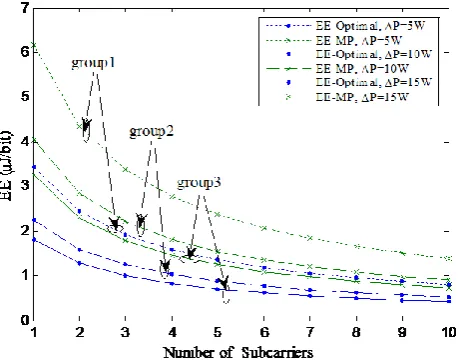
is changed due to the changing of the number of subcarriers (see (12)), so the EE result will not be the same. The tradeoff of EE and SE is that if we achieve a smaller EE (equal to get a better EE performance), we will get a smaller SE (equal to get a worse SE performance) at the same time, the vice versa. The tradeoff of EE and SE is different when the number of subcarriers is different. When the number of subcarriers is larger than 4, the trends of EE and SE are almost the same with the situation where the number of subcarriers is 4, so their EE and SE tradeoff are almost the same. When the numbers of subcarriers are smaller than 4, the tradeoff are different. For example, compare two situations where the numbers of subcarriers are respectively one and four. From Fig. 3 we can see that when SE is 10bps/Hz, EE in the two situations are almost the same, but when SE is changed to 20bps/Hz, the EE under one subcarrier is almost the half than the EE under four subcarriers, so the performance loss of EE under the four subcarriers is twice than that under the one subcarrier.Fig. 4 shows the comparison of the optimum EE and the EE calculated through middle point
(EE-MP) of
l
1. Here we fix Pmax and varyk
to get a differentba. We can see from the results that the performance of EE is improved averagely 200% compared to EE-MP in low ba region. Whenba
gradually becomes larger, the optimum EE and EE-MP gradually achieve the same value, which is
because the feasible region becomes gradually small (l1 and l3 are fixed, only l2 is changed), so the
[image:10.595.125.496.92.190.2]Fig. 5 shows the EE results of different numbers of subcarriers. When
k
is fixed, we change thevalue of P to get three group curves. We can see that when P reduces, EE generally gets larger, which means the performance decreases when Pmax becomes larger. We can also see that the EE difference becomes smaller in each group when the number of subcarriers increases while the difference between groups becomes larger, for example, the optimum EE of group 1 improves almost 100% compared to group 3 when the number of subcarriers is 5. This is because when the number of subcarriers in each group increases,
becomes larger, so the feasible region becomes smaller, as theresult, the optimum EE and EE-MP gradually close to each other. However, between the groups, the
change of P will affect l3, changing
. Because
is fixed, so
-
is changed, thus, when k is fixed, ba is changed, so the feasible region will be determined by the two changed factors: ba and l3, thus the variation trends between groups are different from those of the same groups when thenumber of subcarriers increases.
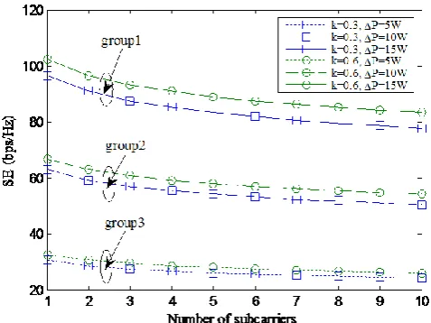
Fig. 6 shows the SE result for different numbers of subcarriers using our optimal method. We change the value of P to get three group curves. For comparison, we also change the value of
k
in each group. From the curves we can see that the SE decreases when the number of subcarriers increases, so if we want to get a higher SE, we should reduce the number of subcarriers. Experiment results also show that the change ofk
can affect SE in some degree, whereas P can influence SE in large degree. The reason for that is that the change ofk
can only affectba, but the change of P can affect not only ba but alsol3, so the change of P has a greater influence for feasible region than that of the change ofk
. If we want to get a higher SE, we should increase P or increasek
, which is useful when we want to improve the overall throughput.Fig. 7 shows the minimum individual rate assignments in two directions under different numbers of subcarriers. Here the minimum individual rate means the minimum transmit rate among different sub-channels when the number of subcarriers is given. The expressions used for the bidirectional bit assignments are (15a) and (15b). We see that the minimum bit assignments in AB direction is lower than the values inBA direction, which is owe to that the overall throughput in AB
direction is larger than that of BA direction. The minimum bit assignment decreases when the number of subcarriers increases, which is because the SE decreases with the number of subcarriers increasing. When the number of subcarriers is fixed, the minimum bit assignment increases when P becomes larger, which is because the SE increases with the increasing of P.
Fig. 8(a) shows the effective channel gain. Fig. 8(c) shows the bit rate assignments in AB
direction and that of BA direction using water-filling method. We also give out the power assignment of each subcarrier in Fig. 8(b). The number of subcarriers used in Fig.8 is 10. From Fig. 8(a) and Fig. 8(c) we can see that the bit rate of individual subcarrier increases when the effective channel
gain increases, which is agree with the formula (15a) and (15b), where i ab
B and i ba
B (i1, 2, ,N) are the increasing functions of
|
|
i eff
h
. From Fig. 8(b) we can see that the power allocation on individual subcarrier increases with the increasing of effective channel gain, which can be explained by
formula (3). From formula (3), we can see that
P
ti (i1, 2, ,N) are determined byi ab B , Bbai and
|
|
i eff
h
. Because i ab
B andBbai affect
P
ti by exponential form, so they have a greater influence to it
P
than that of
|
|
i effh
. Therefore, the trends of
P
ti are the same with that ofi ab
Fig.3. EE verses SE using proposed scheme with the number of subcarriers changed, where P0.5W.
Fig.4. EE verses ba using proposed scheme and EE-MP method, where P0.5W, the number of subcarriers is 4.
[image:12.595.196.426.511.691.2]Fig. 6. SE verses number of subcarriers using proposed scheme and EE-MP method with k and P changed.
Fig. 7. Bi-directional minimum individual rate verses number of subcarriers with P changed.
(b) Power allocation on individual subcarrier.
[image:14.595.179.425.77.470.2](c) Bidirectional bit allocation on individual subcarrier.
Fig. 8. Channel conditions and the corresponding assignments of power and bit on each subcarrier, where the number of subcarriers is 10, P0.5W, 1, 23.
VI. CONCLUSION
In this paper, we have investigated the optimal EE in two-way OFDM relay system, where the constraints of delay-tolerant QoS and total power consumption are simultaneously considered. We minimize EE by bidirectional bit allocation, which first finds the optimal total bit allocation respectively in two directions by searching the bounds of the feasible region, then assigns the corresponding total bit value on subcarriers using water-filling method. The dimension of the variants optimized is reduced from 2N to 1. Simulation results show that our algorithm can on average provide nearly 200% radio energy efficiency performance enhancement than the one without EE optimization. The EE changes when the bounds of feasible region are varied through the number of subcarrier. We also show that as the performance of EE increases when SE decreases, one should make a balance between two factors, which is the subject of future investigations.
ACKNOWLEDGMENT
APPENDIX A
PROOF OF WATER-FILLING ASSIGNMENT FOR PROBLEM 2
From the constraints of problem 2, we can see that the minimum
EE is obtained when,
(
ab)
T ba
P B B achieves its minimum value. Observe the expression of PT
(
Bab,
Bba)
from (5) and the constrains (8a) and (8b), we find that the first term in PT(
Bab,
Bba)
is associated withB
abi but not withB
bai , while the second term is a function ofB
bai but not ofB
abi , besides, all the constrains oni ab
B
andB
bai are independent. Therefore, problem 2 can be decomposed into two sub-problems respectively forB
abi andB
bai with similar form. Take the optimization problem forB
abi as an example, which is/ 0 2 1 1 min (20 ) (2 1) (20 ) 2 | |
. . , 0.
,
i ab i ab B TW N i eff N i iab ab ab i N B i b N a h
s t B B B
The optimal problem is a convex optimization [34], the Lagrangian function of (20) is given by
/ 0 2 1 1 1 1 1 (2 1)
2 | |
(
, ,
)
(
),
i ab B TW N N i i eff N N i ii ab ab ab
i i
N
h
L
B
B
B
abB
λ
where
λ
( ,
1 2,
N)
.
1andi,
i
1,
,
N
are Lagrangian multipliers. The Karush-Khun-Tucker (KKT) conditions are given as
1
(21 )
0, (21 )
0, (21 )
, (21 )
0, (21 )
0, i i ab N i ab ab i i i ab f a B b
B B c
e B
L
ab Bfrom (21a),we can get
0 /
1
2 0 , 1 , , , ( 2 2 )
l n 2 2 2 | |
i ab i ab B TW N i i eff L i N B N N TW h
therefore, we get
0 /
1 2
l n 2
2 , ( 2 3 )
2 | |
i ab B TW N i i eff N N TW h
substitute (23) into (21b), we have
0 /
1 2
ln 2
2 0, (24)
2 | |
observe (24), together with (21e) and (21f), we can get
2
2 1
0
2 | |
max( log , 0), (25)
ln 2 i eff i ab TW h TW B
N N N
substitute (25) into (21c), we can get the value of 1. Therefore, the water-filling assignment for
problem 2 is proved.
APPENDIX B PROOF OF THEOREM 1
LetATW, 0
1
1 2
2 ln 2
(| N | )N
eff eff
TW
N N
B h h . From (13a) and (13b), we get
2 1 2 2 (26 ) (26 ) log log
,
,
ab ba a bB A B
B A B
substitute (26a) and (26b) into (16), we get
1 2 0 2
1
2 1 2 2
2
1
( )
ln 2 | |
(27)
log log
.
N i i eff EE T TW N h
A B A B
Suppose the optimal feasible point * *
1 2
( , )
D of problem 3 is the interior point of the feasible
region, then the following equations must establish [34]
* * * *
1 1 2 2 1 1 2 2
1 , 2 ,
(28)
0.
EE EE
We have 2 21 2 0 2
2 1 2
1
2 2 2
2 1 2 2 1 2
2
2 [
log 1
( ( ) )
log
ln 2 | |
ln 2
, 1, 2. (29)
( log ) ( log )
]
N i i i eff EE i TA e TW
ATW N
B
h i
A B A B
Substitute (29) into (28), after some arrangements, we get
* *
1 2 0
* * 2
1
1 2
1 1 1
( )( ( ) ) 0, (30)
ln 2 | |
N i i eff TW N h
we can easily prove that the second term of the left side of the equation above can not be zero under the conditions of (12a) and (12b) unless all the channel coefficients are the same, therefore we get
* *
1 2
*
. Substitute it into (28), along with (29), we get* * 2 *
2 0 2
1
2 1
log ( ) (31)
ln 2 | |
,
Ni i eff
TW
TW B N
h
we can prove that the equation (31) has no solution. A brief interpretation is followed.
Note that the right side of (31) is a linear function f(*), whose slope is 1 2
ln 2 TW
k
, also note thatthis line passes through point 0
2 1 1 | |
(0,
)
N i i eff N hE
*
( )
g . Assume that a line
l
is tangent with g(*) and passes through point E, after somecalculations, we can get that the slope of
l
is1
1 2 2
2 2
1
2
1
log [ (| | ) ( )]
| |
,
N N N
eff eff i
i eff
k TW e h h
h
we can prove that
k
2
k
1, because the geometric mean is bigger than the harmonic mean, that is to say
1
1 2
2 1
(| | )
1 | |
,
N N eff eff N
i i eff
N h h
h
when
k
2
k
1, it can be proved that *( )
f and *
( )
g have no intersection point, which can be
showed through the following graphic illustration.
[image:17.595.179.432.273.485.2]The graphics for f(*) and g(*) are showed below:
Fig. 9 The illustration for f(*) and g(*)
Based on (12a), (12b) and the definition of B, we can prove that * 1
B
, so *( ) 0
g . The images
of f(*),g(*) and l are showed in Fig. 9, because
k
2
k
1, f(*) and g(*) have no intersection point, thus equation (31) has no solution. Theorem 1 is proved.Competing interests
The authors declare that there is no conflict of interest regarding the publication of this article.
REFERENCE
[1] E. Shih, S. H. Cho, N. Ickes, R. Min, A. Sinha, A. Wang, and A. Chandrakasan, “Physical layer driven protocol and algorithm design for energy-efficient wireless sensor networks,” in ACM MobiCom’01, July 2001.
[2] C. Isheden and G. P. Fettweis, “Energy-efficient multi-carrier link adaptation with sum rate-dependent circuit power,” in Proc. 2010 IEEE Globecom.
[3] T. Wang, and L. Vandendorpe, “On the optimum energy efficiency for flat-fading channels with rate-dependent circuit power,” IEEE Trans. Commun., vol. 61, no. 12, pp. 4910-4921, Dec. 2013.
[4] G. Miao, N. Himayat, and G. Y. Li, “Energy-efficient link adaptation in frequency-selective channels,” IEEE Trans. Commun., vol. 58, no. 2, pp. 545-554, Feb. 2010.
[5] C. Sun, Y. Cen, and C. Yang, “Energy efficient OFDM relay systems,” IEEE Trans. Commun., vol. 61, no. 5, pp.1797-1809, May 2013.
[6] R. Pabst, B. H. Walke, D. C. Schultz, P. Herhold, H. Yanikomeroglu, S. Mukherjee, H. Viswanathan, M. Lott, W. Zirwas, M. Dohler, H. Aghvami, D. D. Falconer, and G. P. Fettweis, “Relay-based deployment concepts for wireless and mobile broadband radio,” IEEE Commun. Mag., vol. 42, no. 9, pp. 80-89, Sep. 2004.
4, pp. 233-235, Apr. 2009.
[8] J. Yang, P. Fan, T. Q. Duong, and X. Lei, “Exact performance of two-way AF relaying in Nakagami-m fading environment,” IEEE Trans. Wireless Commun., vol. 10, no. 3, pp. 980-987, Mar. 2011.
[9] I. Krikidis, “Relay selection for two-way relay channels with MABC DF: A Diversity Perspective,” IEEE Trans. Veh. Technol., vol. 59, no. 9, pp. 4620-4628, Nov. 2010.
[10] Y. Yang, and S. Aissa, “Information-guided transmission in decode-and-forward relaying systems: spatial exploitation and throughput enhancement,” IEEE Trans. Wireless Commun., vol. 10, no. 7, pp. 2341-2351, July 2011.
[11] S. Zhang, S. C. Liew, P. P. Lam, “Physical-layer network coding,” in ACM MobiCom’06, Sep. 2006.
[12] S. Katti, H. Rahul, W. Hu, D. Katabi, M. Médard, and J. Crowcroft, “XORs in the air: Practical wireless network coding,” IEEE/ACM Trans. Netw., vol. 16, no. 3, pp. 497-510, Jun. 2008.
[13] V. T. Muralidharan, and B. S. Rajan, “Performance analysis of adaptive physical layer network coding for wireless two-way relaying,” IEEE Trans. Wireless Commun., vol. 12, no.3, pp. 1328-1339, Mar. 2013.
[14] B. Nazer, and M. Gastpar, “Reliable physical layer network coding,” Proc. IEEE, vol.99, no.3, pp. 438-460, Mar. 2011. [15] S. Zhang, S. C. Liew, and P. P. Lam, “On the synchronization of physical-layer network coding,” in Proc. IEEE Inf. Theory
Workshop, Chengdu, China, Oct. 2006, pp. 404-408.
[16] C. K. Ho, R. Zhang, and Y. C. Liang, “Two-way relaying over OFDM: optimized tone permutation and power allocation,” in Proc. 2008 IEEE ICC.
[17] W. Dang, M. Tao, H. Mu and J. Huang, “Subcarrier-pair based resource allocation for cooperative multi-relay OFDM systems,” IEEE Trans. Wireless Commun., vol. 9, no.5, pp. 1640-1649, May 2010.
[18] S. Shahbazpanahi and M. Dong, “Achievable rate region and sum-rate maximization for network beamforming for bi-directional relay networks, ” in Proc. 2010 IEEE ICASSP.
[19] C. Xiong, G. Y. Li, S. Zhang, Y. Chen, and S. Xu, “Energy-and spectral-efficiency tradeoff in downlink OFDMA networks,” IEEE Trans. Wireless Commun., vol. 10, no. 11, pp. 3874-3886, Nov. 2011.
[20] C. Xiong, G. Y. Li, S. Zhang, Y. Chen, and S. Xu, “Energy-efficient resource allocation in OFDMA networks,” IEEE Trans. Commun., vol. 60, no. 12, pp. 3767-3778, Dec. 2012.
[21] W. Guo and T. O’Farrell, “Relay deployment in cellular networks: planning and optimization,” IEEE J. Sel. Areas Commun., vol. 31, no. 8, pp. 1597-1606, Aug. 2013.
[22] J. Qu, Y. Cai, and W. Yang, “Energy-efficient joint resource allocation in two-way OFDM relay system,” in IEEE ICIST, Yangzhou, Jiangsu, China, pp. 1237-1241, Mar. 2013.
[23] X. Wang, G. B. Giannakis, and A. G. Marques, “A unified approach to QoS-guaranteed scheduling for channel-adaptive wireless networks,” Proc. IEEE, vol. 95, no.12, pp. 2410-2431, Dec. 2007.
[24] S. Kim and Y. H. Lee, “Energy-efficient power allocation for OFDM signaling over a two-way AF relay,” IEEE Trans. Veh. Technol., vol. 64, no. 10, pp. 4856-4863, Oct. 2015.
[25] C. Xiong, L. Lu and G. Y. Li, “Energy-efficient OFDMA-based two-way relay,” IEEE Trans. Commun., vol. 63, no. 9, pp. 3157-3169, Sep. 2015.
[26] E. Bedeer, A. Alorainy, M. J. Hossain, O. Amin, and M. S. Alouini, “Fairness-aware energy-efficient resource allocation for AF co-operative OFDMA networks,” IEEE J. Sel. Areas Commun., vol. 33, no. 12, pp. 2478-2493, Dec. 2015.
[27] W. Guo, S. Wang, C. Turyagyenda, and T. O’Farrell, “Integrated cross-layer energy savings in a smart and flexible cellular network,”in Proc. 2012 IEEE ICCC.
[28] S. Cui, A. J. Goldsmith, and A. Bahai, “Energy-constrained modulation optimization,” IEEE Trans. Wireless Commun., vol. 4, no. 5, pp. 2349-2360, Sep. 2005.
[29] C. Sun and C. Yang, “Energy efficiency analysis of one-way and two-way relay systems,” EURASIP J. Wireless Commun. and Networking, vol. 2012, no. 46, pp. 1-18, Feb. 2012.
[30] H. A. Suraweera, P. J. Smith, A. Nallanathan, and J. S. Thompson, “Amplify-and-Forward relaying with optimal and suboptimal transmit antenna selection,” IEEE Trans. Wireless Commun., vol. 10, no. 6, pp. 1874-1885, June 2011. [31] Q. Jiang, H. Chen, and X. Liao, “Joint power allocation and subcarrier assignment for two-way OFDM multi-relay system,”
in Proc. 2013 IEEE WCNC.
[32] F. He, Y. Sun, L. Xiao, X. Chen, C. Y. Chi, and S. Zhou, “Capacity region bounds and resource allocation for two-way OFDM relay channels,” IEEE Trans. Wireless Commun., vol. 12, no. 6, pp. 2904-2917, June 2013.
[33] Y. Ma, N. Yi and R. Tafazolli, “Bit and power loading for OFDM-based three-node relaying communications,” IEEE Trans. Signal Process., vol. 56, no. 7, pp. 3236-3247, July 2008.
[34] S. Boyd and L. Vandenberghe, Convex Optimization. Cambridge University Press, 2004.
[35] Q. Cui, T. Yuan, X. Tao, A. A. Dowhuszko, and R. Jäntti, “Energy efficiency analysis of two-way DF relay system with non-ideal power amplifiers,” IEEE Commun. Lett., vol. 18, no. 7, pp. 1254-1257, July 2014.
[36] H. Yu, Y. Li, X. Zhong, L. Wang, and J. Wang, “The analysis of the energy efficiency for the decode-and-forward two-way relay networks,” in Proc. 2013 IEEE WCNC: PHY.