Design & Implementation of JPEG2000 Encoder using VHDL
Kanchan H. Wagh, Pravin K. Dakhole, Vinod G. Adhau
Abstract
This paper deals with the design and implementation of JPEG2000 Encoder using Very High Speed Integrated Circuit Hardware Description Language (VHDL). The new still compression image standard, JPEG2000 has emerged with a number of significant features that would allow it to be used efficiently over a wide variety of images. The scalability of the new standard is intended to allow trading off between compression rates and quality of images. Due to multi-resolution nature of wavelet transforms, they have been adopted by the JPEG2000 standard as the transform of choice. In this paper, an implementation for a reconfigurable fully scalable Integer Wavelet Transform (IWT) unit that satisfies the specifications of the JPEG2000 standard has been presented. The implementation is based on the lifting scheme, which is the most computation efficient implementation of the discrete wavelet transform.
Key Words- JPEG2000, Run Length Encoder, Wavelet transform, Le-Gall 5/3-filter bank, Lifting scheme, data compression.
1. Introduction
The most common form of image compression is known as JPEG. The joint photographic Expert Group in the late 1980’s developed this standard. The committee’s first published standard was named as Baseline JPEG. In 1996’s, JPEG committee began to investigate possibilities for new image compression standard that can serve current & future applications. This initiative was named as JPEG2000.The implementation of the JPEG2000 arithmetic encoder was written in the VHDL.
The paper is organized in the following way. In section 2 the main areas of application & their requirement are given. The architecture of the standard is described in section 3. It contains the general block diagram of JPEG 2000. In section 4 in short DWT is explained. In section 5 the Lifting scheme is described, which is the most computation efficient implementation of the discrete wavelet transform.
In section 6 the Block diagram, Design and Simulation of the different blocks namely Huffman coder, Quantizer and Level Shifter are reported.
Ms. Kanchan H. Wagh , Department of Electronics and Communication Engineering , VLSI Laboratory, Yeshwantrao Chavan College Of Engineering , Nagpur, India (Mobile-+919922016452, Phone No.-+917122286333, e-mail: [email protected])
Pravin K. Dakhole, IEEE Member, Department of Electronics and Communication Engineering , VLSI Laboratory, Y.C.C.E College, Nagpur ,(e-mail:[email protected])
Vinod G. Adhau, Department of Electronics and Communication Engineering , VLSI Laboratory, Y.C.C.E College, Nagpur, (e-mail:[email protected])
2. Applications-Requirement-Features
The JPEG 2000 standard provides a set of features that are of vital importance to many high-end and emerging applications, by taking advantage of new technologies. It addresses areas where current standards fail to produce the best quality or performance and provides capabilities to markets that currently do not use compression. The markets and applications better served by the JPEG2000 standard are Internet, color facsimile, printing, scanning (consumer and pre-press), digital photography, remote sensing, mobile, medical imagery, digital libraries / archives & E-commerce. Each application area imposes some requirements that the standard should fulfil [1]. The features that this standard should possess are the following:
2.1 Superior low bit-rate performance:
This standard should offer performance superior to the current standards at low bit-rates (eg. Below 0.25 bpp for highly detailed gray-scale image). This significantly improved low bit-rate performance should be achieved without sacrificing performance on the rest of the rate-distortion spectrum. Examples of applications that need this feature include network image transmission & remote sensing. This is the highest priority feature.
2.2 Continuous-tone and bi-level compression:
It is desired to have a coding standard that is capable of compressing both Continuous-tone and bi-level image. If feasible, this standard should strive to achieve this with similar system resources. The system should compress & decompress image with various dynamic ranges (e.g. 1bit to 16 bit) for each color component. Example of application that can use this feature include compound documents with images & text, medical images with annotation overlays, and graphic and computer generated images with binary and near to binary regions, alpha and transparency planes, and facsimile.
2.3 Lossless and lossy compression:
application that supply devices with different capabilities & resources, and pre-press imagery.
2.4 Progressive transmission by pixel accuracy and resolution:
Progressive transmission that allows images to be reconstructed with increasing pixel accuracy or spatial resolution is essential for many applications. This feature allows the reconstruction of images with different resolutions & pixel accuracy, as needed or desired, for different target devices. Example of applications includes the World Wide Web, image archival application & printers.
2.5 Random code stream access and processing:
Often there are parts of an image that are more important than other. This features allows user define Regions-Of-Interest (ROI) in the image to be randomly accessed and/or decompressed with less distortion then the rest of image. Also, random, translation, filtering, features extraction and scaling.
2.6 Robustness to bit-errors:
It is desirable to consider robustness to bit-errors while designing the code stream . One application where this is important is wireless communication channels. Portions of the code stream may be more important than others in determining decoded image quality. Proper design of the code stream can aid subsequent error correction systems in alleviating catastrophic decoding failures.
2.7 Open architecture:
It is desirable to allow open architecture to optimise the system for different image types & applications. With this feature, a decoder is only required to implement the core tool set & a parser that understands the code stream. If necessary, unknown tools are requested by the decoder & sent from the source.
2.8 Sequential build-up capability (real time coding):
The standard should be capable of compressing & decompressing images with a single sequential pass [1]. This standard should also be capable of processing an image using component interleave order or non-interleaved order. During compression & decompression, the standard should use context limited to a reasonable number of lines.
3. Architecture of the standard
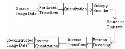
Figure 1 shows the block diagram of JPEG 2000 encoder and decoder. The source encoder reduces or eliminates any source coding, interpixel, psychovisual redundancies in the input image [1]. The DWT is first applied on source image
[image:2.612.339.543.61.141.2].
Figure 1 : Block diagram of JPEG2000 Encoder and Decoder
data. The transform coefficients are then quantized and entropy coded, before forming the output code stream (bit stream).The decoder is reverse of the encoder (Fig 1) .The code stream is first entropy decoded, dequantised and inverse discrete transformed, thus resulting in the reconstructed image data. The quantization reduces the precision of the values generated from the encoder & therefore reduces the number of bits required to save the transform coefficients. This process is lossy . An entropy encoder further compresses the quantized values. This is done to achieve better compression. The various commonly used entropy encoder are the Huffman encoder, arithmetic encoder. In this paper Huffman encoder is designed & simulated.
4. The Discrete wavelet Transform
Discrete wavelet transformation (DWT) transforms discrete signal from time domain into time frequency domain. The transformation product is set of coefficient organized in the way that enables not only spectrum analyses of the signal, but also spectral behavior of the signal in time. This is achieved by decomposing signal, breaking it in to two components, each caring information about source signal. In wavelet transform, dilation & translation of a mother wavelet are used to perform a spatial/frequency analysis on the inputs data varying the dilation & translation of the mother wavelet, produces a customization time/frequency analysis of input signal compared to traditional DCT-based processing, DWT yields higher compression ratio & better visual quantity [2].
5. The lifting scheme
Figure 2: Split, predict and update phases in lifting scheme (forward transform)
Lifting scheme representation for the 5/3 Le Gall Wavelet filters. In our design for the hardware lifting scheme-based DWT module, here we choose 5/3 Le-Gall filter .The JPEG2000 standard committed has recommended using the Le-Gall Wavelet filters for the integer mode operation. The following equations shows how the lifting equation for the Le-Gall filters along with the block diagram can be derived.
Filter transforms equation:
2 1
( ) 1 1 3 1 1
8 4 4 4 8
z
h = − z− + z− + + z− z−2
---(1)
i 2 1
( )
1 1
4 2
z
g = z− − z− +1
4
---(2)
The factorized polyphase matrix for the Le Gall Filter is
i
( )
1 1 1 1 1 0
1 4 4
1 1
0 1
0 1
2 2
Z
z p
z
⎛ ⎞⎛ + ⎞⎛
⎜ ⎟⎜ ⎟⎜
= ⎜⎜ − ⎟⎜⎟⎜ ⎟⎜⎟⎜− −
⎝ ⎠⎝ ⎠⎝
1 1 2
⎞ ⎟ ⎟
− ⎟
⎠
i+
2i
x
+
---(3)
the lifting equation can then be directly obtain:
2 1i 0.5( 2i 2i 2 2 1)
y + = − x +x + +x
---(4)
2i 0.25( 2 1i 2i 3)
y = y + +y +
---(5)
[image:3.612.328.519.54.162.2]Using above equation, one can sketch how the lifting scheme based realization for the 5/3 Le Gall filter would look like Figure 4. Represent the basic building block of the 1D-DWT using Le Gall filters since all coefficients are multiples of 2, all multiplication & division can be replaced by shifting operations. The idea behind this technology is that lifting of the high-pass sub-band can be seen as prediction of the odd samples from the even samples.
Figure 3: Implementation of the wavelet transform of L- Gall filter.
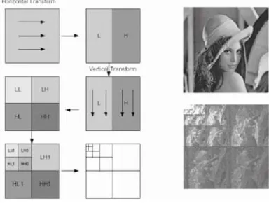
[image:3.612.48.298.56.148.2]Figure 3 shows interesting property of the lifting representation, where predict or update lifting steps are applied. All the samples in the stream are replaced by new samples and at any time we need only the current streams to update sample. In lifting literature, the two basic steps are the predict step, and the update step. The idea behind this terminology is that lifting of the high-pass sub band with the low- pass sub band can be seen as prediction of the odd samples from the even samples. The 2D-DWT was obtained by performing the designed 1D-DWT on both the rows and columns. Figure 4 shows how the 2D-DWT modules operate on an input image and what would be the final output.
Figure 4: JPEG2000 compression
[image:3.612.346.538.378.523.2]6. Design and Simulation
This project aims to provide modules designed & simulated using VHDL that can be used to accelerate an existing software implementation of JPEG2000 encoder.
Figure 5.Block diagram of JPEG compression
Figure 5 shows the block diagram of JPEG compression which is designed & presented in this paper. It consists of preprocessing, DWT (Discrete Wavelet Transform), Quantization, RLE (Run length Encoder) and Entropy coder (Huffman Coder).
6.1Reading the original Image
The original image which is uncompressed is stripped off with its header information. Only the necessary information is retained while reading the image header. These are number of rows and number of columns in the image. The image size is then calculated which is equal to the product of number of rows and columns. The information after the header inside the image is the pixel intensities. These values are then read in an array of integers. The image is ready for further processing.
6.2 Wavelet Transform Routine
The basic concept behind wavelet transform is hierarchically decompose an input signal into a series of successively lower resolution reference signals and their associated detail signals. At each level, the reference signal and their associated detail signal contain the information needed to reconstruct the reference signal at the next higher resolution level.
The Wavelet transform routine employs a lifting scheme to simplify the wavelet transform implementation. Therefore, it only requires integer add and shift. The DWT can be irreversible or reversible [1]. The standard support two filtering modes: a convolution based and a lifting based. Convolution-based filtering consists of performing a series of dot products between the two filter masks and the extended 1-D signal. Lifting-based filtering consists of a sequence of very simple filtering operations for which alternately odd sample values of the signal are update with a weighted sum of even sample values and even sample values are updated with a weighted sum of odd sample values. For the reversible (lossless) case the results are rounded to integer values. The lifting scheme is an alternative method of computing the wavelet coefficients
Advantages of the lifting scheme
• Requires less computation and less memory.
• Easily produces integer-to-integer wavelet transforms for lossless compression.
• Linear, nonlinear, and adaptive wavelet transform is
feasible, and the resulting transform is invertible and reversible.
Coded Image image
Preproc essing
Quanti zation
Huffman Coding
DWT RLE
For lifting scheme level shifter design is implemented which calculates the average of sample values (add and shift operation). Figure 6 shows the simulation waveform of level shifter.
6.3 Quantization
[image:4.612.326.569.327.501.2]Image compression using vector quantization [VQ] is a lossy compression. Qunatization is the process by which the coefficients are reduced in precision. This operation is lossy unless the quantization step 1 and coefficients are integers as produced by reversible integer 5/3 wavelet. After quantization the result obtained is shown in figure 7. Quantization is an extremely important step in the JPEG
figure 6 : Simulation result of Level Shifter
reconstructed image. Blocking artifacts indicate high spatial frequencies caused by an absence of AC coefficients [5]. Essentially, quantization, when used effectively, will result in high compression, with minimal loss in quality. Figure 7 shows the simulation waveform of quantizer.
Types of Quantizer
Quantizer can either be linear or non-linear. Linear quantization is when input values map to a set of evenly distributed output values. This is adequate when a high level of precision is required across the entire range of possible input values. Non-linear modes treat each input value differently.
6.4 Run Length Encoding
RLE is the next routine following the quantization process. The basic concept is to code each contiguous group of 0’s encountered in a scan of a row by its length and to establish a convention for determining the value of the run . This is shown as an example in Figure 8. RLE is useful for compressing data that contains repeated values e.g. output from a filter, many consecutive values are 0. It is very simple compared with other compression technique. RLE is reversible (Lossless) compression technique. In this decomposition is just an easy. The RLE algorithm may be adapted to suit the needs, but the main idea is to replace runs of the same data (like 'aaaaa' or '00000') with a counter saying how many repetitions are there. The idea is quite simple.
[image:5.612.44.281.423.615.2]
many repetitions.
[image:5.612.336.554.472.557.2]figure 7 : Simulation result of Quantizer
Figure 8 : An example of RLE
The purpose of this step is to compress the image size based on the pixel values from quantization, which are between integer values 0 to 16. The image can be compressed as much as up to 10% of the original after the run length encoding. As in the quantization routine, the image is also divided into 10 blocks. Each block will run the same run-length encoding algorithm.
6.5 Entropy Coding Routine
The last routine in the image wavelet compression algorithm is entropy coding .This process based on calculation result from run length encoding .Using Huffman coding algorithm for the entropy coding the resulting image file can be compress as much as up to 2 - 3% of the original image size .In the algorithm two 256 size integer arrays are used to hold the parameters for a fixed Huffman coding tree. Huffman coding is an error free (lossless) compression technique. The principle method of this technique is to encode more probability data by the less bit code . It can be summarized as following algorithm
1. Find the probability of each data and sort them
2. Generate new node by combination the two smallest probabilities together then sort the probability of new node with the remainder probabilities.
3. Define 1 for a branch of new node and 0 for another. 4. Repeat step 2 and 3 until the final probability is 1.0.
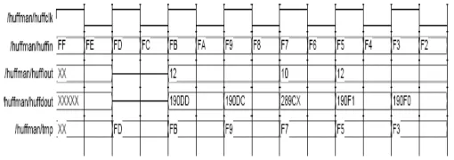
[image:5.612.322.577.599.689.2]An example of Huffman coding can be shown in figure 9 and figure10 shows the resulting waveform of Huffman coder.
Figure 9 : An example of Huffman coding
[image:5.612.48.237.657.742.2]Figure 5 module is implemented using Modelsim version. The implementation of JPEG 2000 arithmetic encoder was written in the VHDL language .Following are the important reasons why this language was used. VHDL is widely used for creating designs that will be programmed into FPGA devices. It is general and versatile language in which to design a digital system. It is true that sections of c encoder design produced that are tied to FPGA architecture. However, using VHDL allows as much of the design as possible to be portable to other synthesis tools.
Implementing the JPEG 2000 encoder in VHDL therefore results in a much simpler design flow than if alternate language entry technique had been used. The Simulation are performed on Modelsim and the design synthesis is done using Altera Quartus II software. The image is given as an input and on that image DWT transform is applied for image compression. Then the image is compress by different compression techniques like quantizer, Run length encoder (RLE) and Huffman Coder (Entropy Encoder). Individual module is tested to meet the specifications of JPEG2000.
References
[1] A.N.Skodras,C. A.Christopotlos, T. Evrahimi “JPEG2000 : The Upcoming Still image compression standard ”IEEE transction on Image Processing .vol 11,May 2000.
[2] Georgei Kuzmanov Bahman Zafarifar, Prarthana Shrestha, Stamatis Yassiliadis “Reconfigurable DWT Based On Lifting.”
[3] N. Skodras, T. Evrahimi “JPEG 2000 image coding System Theory and Application.”
[4] Marco Grangetto, Ecrico magli,MaurizioMartina and Gabriellaolmo “Optimization and Implementation of the Integer Wavelet Transform for Image Coding.”