Abstract— A fish-like robot which can swim smoothly has plenty of applications in research and industry. It has extensive monitoring and maneuvering capability attainable at a low driving voltage and has a good response to external stimuli with soft characteristics. This paper presents the methods for making the robot’s motion to be in congruence with that of the human being who operates it, obviating the need for sensors. An efficient design of cost effective robots of various sizes which can be interfaced with a single Teaching hand gripper (THG) designed specifically for the palm and fingers for their operation has also been proposed. The THG is calibrated to overcome the discrepancies among potentiometers used for robot motion. The performance of the proposed system is tested on a robot with a single joint and the results are presented for a simple closed loop system. The robot is given fast, medium and slow responses as inputs such that a variation of 30 degrees is achieved in time intervals of 1, 2 and 3 sec. The output lag and the system efficiency are analyzed. These robots can be efficiently employed in relatively calm underwater surfaces.
Index Terms— Automation, Control, Fish-like, human-robot, System, coordination.
I. INTRODUCTION
The operation of conventional button operated robot has alternatives like voice & physical motion [1, 12, and 13]. The usage of body movement to activate humanoid robots is in vogue and generally costlier due to sensors used in them [14]. This paper presents a new approach to underwater robotics which uses human body movements for operating fish-like robot [7, 11]. The robot designed in the paper may be termed as
F. K. Shyam Ravi Shanker is with Instrumentation and Control Engineering Department, National Institute of Technology, Tiruchirapalli, Tamil Nadu, Trichy - 620015, India (corresponding author to provide phone: +91-9444366455; (e-mail : [email protected]).
S. N.P.Gopalan is with Mathematics and Computer Application Department, National Institute of Technology, Tiruchirapalli, Tamil Nadu, Trichy – 620015, India (e-mail: [email protected]).
T. C. Mala, is with Computer Science and Engineering Department, National Institute of Technology, Tiruchirapalli, Tamil Nadu, Trichy – 620015, India (e-mail: [email protected]).
F. K. Anuja is with the Electrical Engineering Department, University of Concordia, Montreal, Canada. ( e-mail: [email protected]).
F. V. Sridevi is with Instrumentation and Control Engineering Department, National Institute of Technology, Tiruchirapalli, Tamil Nadu, Trichy - 620015, India ( e-mail : [email protected] )
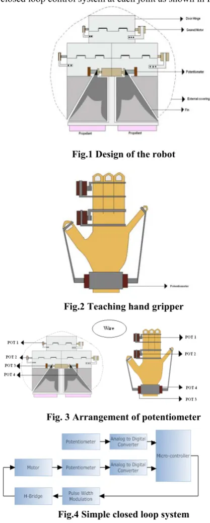
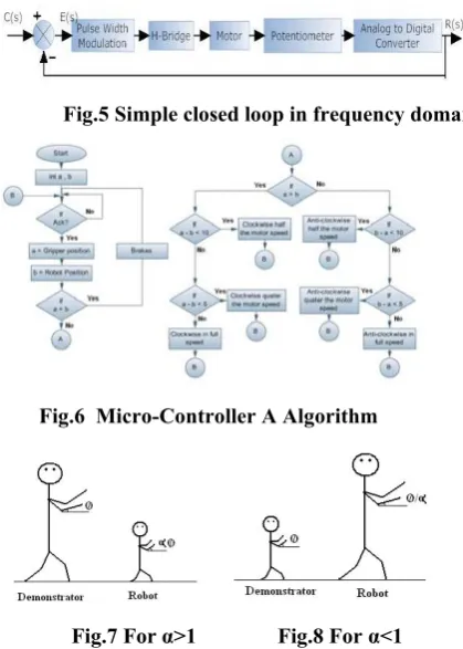
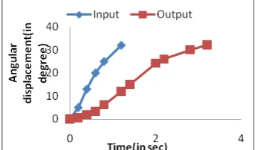
fish-like as its design includes fins for its motion [8, 10]. It may be made to swim through by suitably inflating and deflating it. Non -specification of starting reference point at any instant of time after resumption from a power failure is the most salient feature of present study [2]. The concept of safe activation of robots of different sizes with a single THG by the use of low voltage is another salient feature of the proposed work. The THG and robot have respectively five and four potentiometers in them out of which two is used for fin motion and another set of two is used to control the robot body flexibility. Finally, the fifth one on the THG is used to control the speed of propulsion of the robot. The architecture of the robot is pictorially represented in Fig.1 and the THG is as shown in Fig.2. The fin motion helps the robot to turn and control it even in rough circumstances.
II. PROPOSED WORK
The origin of physical body movement stems out from the angular movement arising at the various joints in our body. Hence the measure of rotational motion at the joints of the demonstrator body is essential for replication at the robot. The Architecture of the robot and the THG plays an important role in the control of the robot [9]. The angular displacement at the joints of the demonstrator gripper is measured with the help of a rotary potentiometer which also serves as an indicator of angular displacement. The exact positioning of the potentiometer is made on the robot, such that the potential variation in both the demonstrator gripper potentiometer and the robot potentiometer are identical as shown in Fig.3.
The position of the robot can be determined from the potentiometer reading from all the joints. A camera attached to the top of the task robot captures the images of the objects and transfers them to the destination which intern guides the robot to perform the desired task [5]. The images are transferred to the destination by using data acquisition tool in Matlab. A propellant kept at the rear of the robot, along with the fins in it, enables the smooth swimming and extensive maneuvering capability. The motion of the robot is enabled by a propellant at the rear with the rotational motion provided by a highly geared motor. The potentiometer and motor are mounted in such a way that the variation in the demonstrator setup has an impact on the robot setup resulting in the matching of positions. The two
Human – Robot Coordination For Multi –
Sized Fish-Like Robot Using Wired
Communication
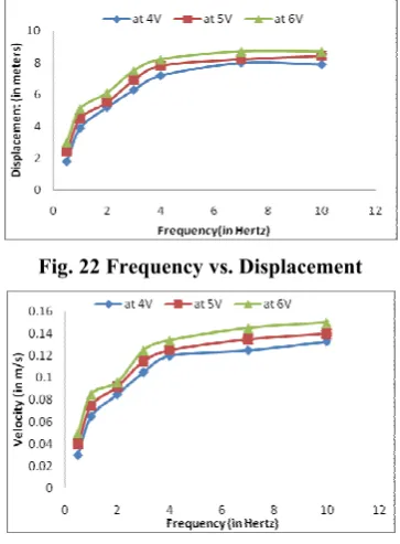
propellants kept at the rear side of the robot, are used to move the robot forward using heavily geared motors [6]. The position of the THG and the robot is correlated by forming a simple closed loop control system at each joint as shown in Fig.4.
Fig.1 Design of the robot
Fig.2 Teaching hand gripper
[image:2.595.45.254.128.648.2]Fig. 3 Arrangement of potentiometer
Fig.4 Simple closed loop system
III. WORKING PRINCIPLE A. Closed Loop System for replication process
The development of control systems for robot manipulators with redundant kinematics is still a demanding task [3, 4]. This task becomes even more challenging if the robots to be controlled operates in partly unknown
environments which vary over time and may be thousands of kilometers away from the operator, for example in space. The motor is connected with the potentiometer, thus causing the potentiometer to rotate and correct the error, resulting in least error as far as possible. Depending on the error the input to the motor applied is decided by the H- Bridge circuit, to either rotate in clockwise or anti-clockwise as shown in Fig.5. If the error is positive, positive potential is applied to the motor which overcomes the error with a positive correction, hence rotating the motor in clockwise direction. If the error is negative, negative potential is applied to the motor which corrects the error with a negative correction, thereby rotating the motor in counter clockwise direction. The equation to compute error is given by
E(s) = C(s) – R(s) (1) E(s) – Error
C(s) – Input to the system R(s) – Output from the system
To avoid steady state error and for the error to be zero, the motor speed is varied when the position of the robot is nearer to the THG position. When the difference in position of the robot and the THG is less than 15o, the motor speed is reduced to half by the use of Pulse Width Modulation. When the difference in position of the robot and the THG is less than 7o, the motor speed is reduced to a quarter of the original speed. The algorithm for operation is as shown in Fig.6.
To avoid steady state error and for the error to be zero, the motor speed is varied when the position of the robot is nearer to the THG position. When the difference in position of the robot and the THG is less than 15o, the motor speed is reduced to half by the use of Pulse Width Modulation. When the difference in position of the robot and the THG is less than 7o, the motor speed is reduced to a quarter of the original speed. The algorithm for operation is as shown in Fig.6.
B. Multi-Sized Robot matching with a single designed demonstrator gripper
Condition for the robot to replicate the action performed in THG at each joint is
θ(s) = φ(s)
Where θ and φ is the angle moved by the THG and the robot respectively.
To have a clear idea about the concept, a humanoid robot is taken for reference and illustrated. The condition for a robot of any size to replicate the action performed in the gripper at each joint is
θ(s) = αφ(s) Where α is a constant.
If α=1, Variation of the potentiometer in the robot is same as that of the THG potentiometer as shown in Fig. 3
Fig.5 Simple closed loop in frequency domain
Fig.6 Micro-Controller A Algorithm
Fig.7 For α>1 Fig.8 For α<1
While using different dimensions of robot and THG, the robot cannot replicate the action because the variation of the potentiometer at the joint is dependent on size of the potentiometer used in the robot and THG. Any multi-sized robot replicates the actions of the THG by means of the potentiometer installed which helps in defining a factor and nullify the effect of the variation.
In a transmitter, the factor is defined by the user with the potentiometer as shown in Fig.9 and the factor is multiplied so that the data received in the receiver will be in accordance with the dimensions of the demonstrator gripper as shown in Fig.10. Assumption is made that all the potentiometers at the joints of the robot and the THG are varying by the same factor.
IV. USING WIRED COMMUNICATION A. Demonstrator Gripper Circuit
The THG circuit using wired communication is shown in the Fig.9. The algorithm for microcontroller 1 in the transmitter is shown in Fig.11. The potentiometer rotates up to 320 degrees but no joint in our body has the capacity to rotate more than 270 degrees. So a value is assigned for acknowledgement of cycle completion such that any loss of data will be corrected by the new data received in the next cycle as shown in Fig.12. The output decimal value of 255 is assigned for acknowledgement of completion of one cycle. When the
value of 255 is obtained in the receiver side, the next data transmitted will be considered as new cycle.
B. Fish-like Robot Circuit
[image:3.595.330.520.325.469.2]The block diagram for the circuit in the fish-like robot using wired communication is shown in Fig.13. The algorithm for microcontroller 2 and microcontroller A in the receiver are shown in Fig.11 and Fig.6 respectively. The microcontroller is connected to the decoder to select only one buffer at a time. All the buffers are given parallel connection to the output port of the microcontroller 1, so that it will enable the data to reach only a particular joint. The chip enable pin of the buffer helps to correlate the data from the demonstrator setup to the corresponding joint of the robot. The propellant motor speed is varied by varying the pulse width of the motor with the help of a microcontroller. The input frequency to the propellant motor depends on the potential applied by the demonstrator with the help of potentiometer at the demonstrator gripper. So the frequency is decided in the microcontroller for each voltage by the demonstrator.
Fig.9 Demonstrator Gripper circuitry
Fig.10 Multi–sized robot coordination by adjusting α
V. APPLICATIONS
The proposed model will be of immense use in the following applications:
1. The design proposed is compatible for robots such as humanoid robots, fish-like robots and quadrupled robots.
2. Under water exploration
3. Controlling underwater gadgets and vehicles of various sizes using simpler and easier hand movements. 4. Autonomous design using THG for programming
fish-like robots.
VI. PERFORMANCE ANALYSIS A. Performance of the closed loop system
displacement, velocity, efficiency, propulsion force [2, 6]. For our present study, parameters such as time, frequency, angular displacement, angular displacement lag, efficiency, velocity, displacement and propelling speed are considered. Practical testing introduces a variation of 1.4 degrees which will cause the input of the micro controller to change by one decimal or one hexadecimal. So the variation in the position is determined by the values got as input from the computer and the decimal is converted in terms of degrees. In Fig.16 to 18, the robot is tested by slow, medium and fast responses as inputs such that a variation of 30 degrees is achieved in time intervals of 3, 2 and 1 sec.
Fig.14 Fish-like Robot TABLE I
SPECIFICATION OF THE FISH-LIKE ROBOT
Length 24 cm
Width 20 cm
Height 7 cm
Weight 194 gm
Body bone material Aluminium
Covering material Rubber
Fin material Rubber
The robot’s performance is tested and analyzed under three different scenarios in which input is applied namely Slow, Medium, and fast.
Scenario 1: Slow application of input: This is applicable is situations where the robot is used as a monitor in stagnant water such as swimming pool to prevent occurrence of any accidents, then to get a smooth performance, the input to the robot should be applied slowly as shown in Fig. 18.
Scenario 2: Medium application of input: If the robot is to be used for the exploration in a pond, the variation in the input applied should be medium as in Fig. 17 to enable the robot to
[image:4.595.308.539.98.194.2]swim against the pressure in the pond.
Fig.15 Closed loop system
Scenario 3: Fast application of input: If the robot is to be used for the control of underwater gadgets in a river or sea, then input is to be applied fast as shown in Fig. 16 to get the expected performance.
The efficiency of the performance of the robot under the above mentioned scenarios is experimented in stagnant water and the values noted are plotted in Fig. 19. From this graph, it can be inferred that, for stagnant water the efficiency is high only when there is slow variation in the input applied to the robot. The efficiency reduces with increase in the rate at which the input is applied to the robot.
Further, for the robot used in stagnant water, the lag which is the time taken by the robot to respond to the given input is also measured under the three different scenarios mentioned above and the results are plotted in Fig. 20. It can be seen that the lag of the robot is minimum if the input is applied slowly and the lag increases as the rate at which the input is given is also increased.
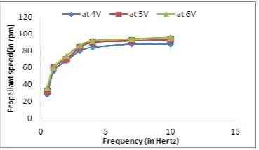
[image:4.595.337.517.537.643.2]Our study is also extended in deciding the frequency of application of voltage to get the required displacement or velocity. The results are plotted in Figs 22 and 23. Moreover, the frequency at which the amount of voltage is to be applied to get the required propellant speed is also found out by experimentation and the results are plotted in Fig. 24. These graphs clearly indicate the amount of voltage to be applied at different frequencies to get the best results in robot movement.
Fig.17 Time vs. Displacement in 2sec
Fig.18 Time vs. Displacement in 3sec
Fig.19 Efficiency vs. Time
Fig.20 Lag in output vs. Time
Since the frontal lobe of the body possesses the capability to oscillate, it helps in smooth swimming at all frequencies. The fish robot has been constructed to be propelled at various angles in the direction of the gravitational force and is analyzed. When the LDR receives light the output becomes high which is processed in the microcontroller for the determination of rpm. Detection of a hole in the shaft disc of the motor indicates 25 percent of one revolution and thus revolution for a minute is determined. The displacement was found by testing the robot to move for 1min and the distance is thus determined. From the displacement and time, the velocity of the fish-like robot was found out. The maximum speed is
attained at 4Hz and the velocity can be varied by changing the frequency of the input.
By varying the value of α, multi-sized human-robot coordination is made possible and successful working with very minute error is obtained. Because of the declaration of α as integer as shown in Fig.11, the percentage error ranges from 0.00392% to 0.388%. For the value of α to be in the range 0 to 2, the resolution was found to be 0.0156 and for a range of 0 to 10, the resolution was found to be 0.0833. To have higher resolution and accuracy, lesser range of values of α should be used.
Fig. 21 RPM measurement setup
VII. CONCLUSION
[image:5.595.324.531.232.297.2]A fish-like robot which can be operated by physical movement using wired communication is designed and tested. From the experimental results, it is shown that swimming speed of the robot can be controlled by changing the frequency of application of voltage. At 4Hz, the voltage was maximum and has the highest velocity. The velocity can be varied by changing the frequency of the input. This proposed work can be extended by controlling the robot movement using wireless communication.
Fig. 22 Frequency vs. Displacement
[image:5.595.336.518.457.704.2]Fig. 24 Frequency vs. Propellant speed
REFERENCES
[1] Ji-Hyoung Lee, Jae-Kwon Kim, and Hyung-Shik Kim, “Development of multi-axis gantry type welding robot system using a PC-based controller”, Industrial Electronics, 2001. Proceedings. ISIE 2001. IEEE International Symposium on Volume 3, 12-16 June 2001 Page(s):1536 - 1541 vol.3 Digital Object Identifier 10.1109/ISIE.2001.931934
[2] N. Delson, H. West, and E.F. Roberts, “Robot programming by human demonstration: the use of human inconsistency in improving 3D robot trajectories”, Intelligent Robots and Systems '94. 'Advanced Robotic Systems and the Real World', IROS '94. Proceedings of the IEEE/RSJ/GI International Conference on Volume 2, 12-16 Sept. 1994 Page(s):1248 - 1255 vol.2 Digital Object Identifier 10.1109/IROS.1994.407519. [3] Chen Yimin, Zhang Tao, Wang Di, and He Yongyi, “A robot simulation,
monitoring and control system based on network and Java3D”, Intelligent Control and Automation, 2002. Proceedings of the 4th World Congress on Volume 1, 10-14 June 2002 Page(s):139 - 143 vol.1 Digital Object Identifier 10.1109/WCICA.2002.1022085.
[4] Y. Izumikawa, K. Yubai, and J. Hirai, “Fault-tolerant control system of flexible arm for sensor fault by using reaction force observer”, Advanced Motion Control, 2004. The 8th IEEE International Workshop on 25-28 March 2004 Page(s):583 - 588 Digital Object Identifier
10.1109/AMC.2004.1297933.
[5] T.S. Jin, and J.M. Lee, “Pose determination of a mobile-task robot using an active calibration scheme”, Industrial Electronics, 2002. ISIE 2002. Proceedings of the 2002 IEEE International Symposium on Volume 2, 8-11 July 2002 Page(s):447 - 452 vol.2. Digital Object Identifier 10.1109/ISIE.2002.1026330.
[6] Shunxiang Guo, Yaming Ge, Lingfei Li, Sheng Liu, "Underwater Swimming Micro Robot Using IPMC Actuator", International Conference on Mechatronics and Automation,june25-28, 2006, Digital Object Identifier:1-4244-0466-5/06
[7] Qingxin Meng,,Hua Wang Ping Li, Liquan Wang,, Ze He, “Dexterous Underwater Robot Hand: HEU Hand II” Mechatronics and Automation, Proceedings of the 2006 IEEE International Conference , June 2006, page(s): 1477 – 1482, Digital Object Identifier: 10.1109/ICMA.2006.257847
[8] Ohata, Satomi Eriguchi, Yu Ishii, Kazuo," AquaBox Series: Small Underwater Robot Systems for Shallow Water Observation", Underwater Technology and Workshop on Scientific Use of Submarine Cables and Related Technologies, 2007. Symposium on 17-20 April 2007, On page(s): 314 - 319,Digital Object Identifier: 10.1109/UT.2007.370796 [9] Gan Yong, Sun Yushan, Wan Lei, Pang Yongjie,” Motion Control
System Architecture of Underwater Robot” Intelligent Control and Automation, 2006. WCICA 2006. The Sixth World Congress on 21-23 June 2006, Volume: 2,page(s): 8876 - 8880, Digital Object Identifier: 10.1109/WCICA.2006.1713716
[10] Chen Hong,,Zhu Chang-an,"Modeling the dynamics of biomimetic underwater robot fish", Robotics and Biomimetics (ROBIO). 2005 IEEE International Conference on 2005, On page(s): 478 - 483, Digital Object Identifier: 10.1109/ROBIO.2005.246314.
[11] Side Zhao,Yuh.J, "Experimental Study on Advanced Underwater Robot Control" Robotics, IEEE Transactions on Aug. 2005, Volume: 21 , Issue: 4, On page(s): 695 - 703,ISSN: 1552-3098, Digital Object Identifier: 10.1109/TRO.2005.844682
[12] Laschi.C, Miwa.H, Takanishi.A, Guglielmelli.E, Dario.P,"Visuo-motor coordination of a humanoid robot head with human-like vision in face tracking" Robotics and Automation, 2003. Proceedings. ICRA '03. IEEE
International Conference on 14-19 Sept. 2003Volume: 1,On page(s): 232 - 237 vol.1,ISSN: 1050-4729,INSPEC Accession Number:7869770 [13] Jarvis.R, "Interactive hand/eye coordination between a human and a
humanoid-a proposal", Intelligent Robots and Systems, 2000. (IROS 2000). Proceedings. 2000 IEEE/RSJ International Conference on,31 Oct.-5 Nov. 2000, Volume: 3, On page(s): 1741 - 1747 vol.3,INSPEC Accession Number:6853250, Digital Object Identifier: 10.1109/IROS.2000.895223